

Recomendados
Más contenido relacionado
La actualidad más candente
La actualidad más candente (19)
Destacado
Destacado (20)
Similar a Cisco labs practical6
Similar a Cisco labs practical6 (20)
Cisco labs practical6
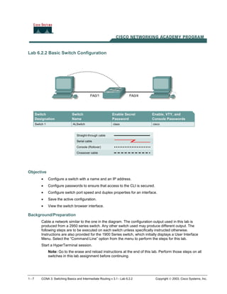
- 1. 1 - 7 CCNA 3: Switching Basics and Intermediate Routing v 3.1 - Lab 6.2.2 Copyright 2003, Cisco Systems, Inc. Lab 6.2.2 Basic Switch Configuration Objective • Configure a switch with a name and an IP address. • Configure passwords to ensure that access to the CLI is secured. • Configure switch port speed and duplex properties for an interface. • Save the active configuration. • View the switch browser interface. Background/Preparation Cable a network similar to the one in the diagram. The configuration output used in this lab is produced from a 2950 series switch. Any other switch used may produce different output. The following steps are to be executed on each switch unless specifically instructed otherwise. Instructions are also provided for the 1900 Series switch, which initially displays a User Interface Menu. Select the “Command Line” option from the menu to perform the steps for this lab. Start a HyperTerminal session. Note: Go to the erase and reload instructions at the end of this lab. Perform those steps on all switches in this lab assignment before continuing.
- 2. 2 - 7 CCNA 3: Switching Basics and Intermediate Routing v 3.1 - Lab 6.2.2 Copyright 2003, Cisco Systems, Inc. Step 1 Enter privileged mode a. Privileged mode gives access to all the switch commands. Many of the privileged commands configure operating parameters. Therefore, privileged access should be password-protected to prevent unauthorized use. The privileged command set includes those commands contained in user EXEC mode, as well as the configure command through which access to the remaining command modes is gained. Switch>enable Switch# 1900: >enable # b. Notice the prompt changed in the configuration to reflect privileged EXEC mode. Step 2 Examine the current switch configuration a. Examine the following current running configuration file: Switch#show running-config b. How many Ethernet or Fast Ethernet interfaces does the switch have? ___________________ c. What is the range of values shown for the VTY lines? _______________________________ d. Examine the current contents of NVRAM as follows: Switch#show startup-config %% Non-volatile configuration memory is not present e. Why does the switch give this response? __________________________________________________________________________ Step 3 Assign a name to the switch a. Enter enable and then the configuration mode. The configuration mode allows the management of the switch. Enter ALSwitch, the name this switch will be referred to in the following: Switch#configure terminal Enter the configuration commands, one for each line. End by pressing Ctrl-Z. Switch(config)#hostname ALSwitch ALSwitch(config)#exit b. Notice the prompt changed in the configuration to reflect its new name. Type exit or press Ctrl- Z to go back into privileged mode.
- 3. 3 - 7 CCNA 3: Switching Basics and Intermediate Routing v 3.1 - Lab 6.2.2 Copyright 2003, Cisco Systems, Inc. Step 4 Examine the current running configuration a. Exam the current configuration that follows to verify that there is no configuration except for the hostname: ALSwitch#show running-config b. Are there any passwords set on the lines? _______________________________________ c. What does the configuration show as the hostname of this switch? ______________________ Step 5 Set the access passwords (1900: Skip to Step 6) Enter config-line mode for the console. Set the password on this line as cisco for login. Configure the vty lines 0 to 15 with the password cisco as follows: ALSwitch#configure terminal Enter the configuration commands, one for each line. End by pressing Ctrl-Z. ALSwitch(config)#line con 0 ALSwitch(config-line)#password cisco ALSwitch(config-line)#login ALSwitch(config-line)#line vty 0 15 ALSwitch(config-line)#password cisco ALSwitch(config-line)#login ALSwitch(config-line)#exit Step 6 Set the command mode passwords a. Set the enable password to cisco and the enable secret password to class as follows: ALSwitch(config)#enable password cisco ALSwitch(config)#enable secret class 1900: ALSwitch(config)#enable password level 15 cisco ALSwitch(config)#enable secret class 2950: #show interface fastethernet 0/4 (Note: this can be a trunk or access port) Or #show interface gigabitethernet 0/1 (Note: this can be a trunk or access port) b. Which password takes precedence, the enable password or enable secret password? _______ Step 7 Configure the layer 3 access to the switch a. Set the IP address of the switch to 192.168.1.2 with a subnet mask of 255.255.255.0 as follows: Note: This is done on the internal virtual interface VLAN 1. ALSwitch(config)#interface VLAN 1 ALSwitch(config-if)#ip address 192.168.1.2 255.255.255.0 ALSwitch(config-if)#exit
- 4. 4 - 7 CCNA 3: Switching Basics and Intermediate Routing v 3.1 - Lab 6.2.2 Copyright 2003, Cisco Systems, Inc. 1900: ALSwitch(config)#ip address 192.168.1.2 255.255.255.0 ALSwitch(config)#exit b. Set the default gateway for the switch and the default management VLAN to 192.168.1.1 as follows: ALSwitch(config)#ip default-gateway 192.168.1.1 ALSwitch(config)#exit 1900: ALSwitch(config)#ip default-gateway 192.168.1.1 ALSwitch(config)#exit Step 8 Verify the management LANs settings (1900: Skip to Step 10) a. Verify the interface settings on VLAN 1 as follows: ALSwitch#show interface VLAN 1 b. What is the bandwidth on this interface? ______________________________ c. What are the VLAN states: VLAN1 is __________, Line protocol is __________ d. Enable the virtual interface using the no shutdown command ALSwitch(config)#interface VLAN 1 ALSwitch(config-if)#no shutdown ALSwitch(config-if)#exit e. What is the queuing strategy? ______________________________________ Step 9 Save the configuration a. The basic configuration of the switch has just been completed. Back up the running configuration file to NVRAM as follows: Note: This will ensure that the changes made will not be lost if the system is rebooted or loses power. ALSwitch#copy running-config startup-config Destination filename [startup-config]?[Enter] Building configuration... [OK] ALSwitch# 1900: b. The configuration is automatically saved to NVRAM within approximately one minute of entering a command. To save the configuration to a TFTP server, enter the following: ALSwitch#copy nvram tftp://tftp server ip add/destination_filename c. Configuration upload is successfully completed.
- 5. 5 - 7 CCNA 3: Switching Basics and Intermediate Routing v 3.1 - Lab 6.2.2 Copyright 2003, Cisco Systems, Inc. Step 10 Examine the startup configuration file (1900: Skip to Step 11) a. To see the configuration that is stored in NVRAM, type show startup-config from the privileged EXEC (enable mode). ALSwitch#show startup-config b. What is displayed? ________________________________________________________ c. Are all the changes that were entered recorded in the file? ____________________________ Step 11 Exit the switch Logoff the switch by typing exit as follows: ALSwitch#exit Once these steps are completed, logoff by typing exit, and turn all the devices off. Then remove and store the cables and adapter.
- 6. 6 - 7 CCNA 3: Switching Basics and Intermediate Routing v 3.1 - Lab 6.2.2 Copyright 2003, Cisco Systems, Inc. Erasing and Reloading the Switch For the majority of the labs in CCNA 3 and CCNA 4 it is necessary to start with an unconfigured switch. Use of a switch with an existing configuration may produce unpredictable results. These instructions allow preparation of the switch prior to performing the lab so previous configuration options do not interfere. The following is the procedure for clearing out previous configurations and starting with an unconfigured switch. Instructions are provided for the 2900, 2950, and 1900 Series switches. 2900 and 2950 Series Switches 1. Enter into the privileged EXEC mode by typing enable. If prompted for a password, enter class (if that does not work, ask the instructor). Switch>enable 2. Remove the VLAN database information file. Switch#delete flash:vlan.dat Delete filename [vlan.dat]?[Enter] Delete flash:vlan.dat? [confirm] [Enter] If there was no VLAN file, this message is displayed. %Error deleting flash:vlan.dat (No such file or directory) 3. Remove the switch startup configuration file from NVRAM. Switch#erase startup-config The responding line prompt will be: Erasing the nvram filesystem will remove all files! Continue? [confirm] Press Enter to confirm. The response should be: Erase of nvram: complete 4. Check that VLAN information was deleted. Verify that the VLAN configuration was deleted in Step 2 using the show vlan command. If previous VLAN configuration information (other than the default management VLAN 1) is still present it will be necessary to power cycle the switch (hardware restart) instead of issuing the reload command. To power cycle the switch, remove the power cord from the back of the switch or unplug it. Then plug it back in. If the VLAN information was successfully deleted in Step 2, go to Step 5 and restart the switch using the reload command. 5. Software restart (using the reload command)
- 7. 7 - 7 CCNA 3: Switching Basics and Intermediate Routing v 3.1 - Lab 6.2.2 Copyright 2003, Cisco Systems, Inc. Note: This step is not necessary if the switch was restarted using the power cycle method. a. At the privileged EXEC mode enter the command reload. Switch(config)#reload The responding line prompt will be: System configuration has been modified. Save? [yes/no]: b. Type n and then press Enter. The responding line prompt will be: Proceed with reload? [confirm] [Enter] The first line of the response will be: Reload requested by console. After the switch has reloaded, the line prompt will be: Would you like to enter the initial configuration dialog? [yes/no]: c. Type n and then press Enter. The responding line prompt will be: Press RETURN to get started! [Enter] 1900 Series Switches 1. Remove VLAN Trunking Protocol (VTP) information #delete vtp This command resets the switch with VTP parameters set to factory defaults. All other parameters will be unchanged. Reset system with VTP parameters set to factory defaults, [Y]es or [N]o? Enter y and press Enter. 2. Remove the switch startup configuration from NVRAM. #delete nvram This command resets the switch with factory defaults. All system parameters will revert to their default factory settings. All static and dynamic addresses will be removed. Reset system with factory defaults, [Y]es or [N]o? Enter y and press Enter.
- 8. 1 - 5 CCNA 3: Switching Basics and Intermediate Routing v 3.1 - Lab 6.2.3 Copyright 2003, Cisco Systems, Inc. Lab 6.2.3 Managing the MAC Address Table Objective • Create a basic switch configuration. • Manage the switch MAC table. Background/Preparation Cable a network similar to the one in the diagram. The configuration output used in this lab is produced from a 2950 series switch. Any other switch used may produce different output. The following steps are to be executed on each switch unless specifically instructed otherwise. Instructions are also provided for the 1900 Series switch, which initially displays a User Interface Menu. Select the “Command Line” option from the menu to perform the steps for this lab. Start a HyperTerminal session. Note: Go to the erase and reload instructions at the end of this lab. Perform those steps on all switches in this lab assignment before continuing. Step 1 Configure the switch Configure the hostname, access and command mode passwords, as well as the management LAN settings. These values are shown in the chart. If problems occur while performing this configuration, refer to the Basic Switch Configuration lab. Step 2 Configure the hosts attached to the switch Configure the hosts to use the same IP subnet for the address, mask, and default gateway as on the switch.
- 9. 2 - 5 CCNA 3: Switching Basics and Intermediate Routing v 3.1 - Lab 6.2.3 Copyright 2003, Cisco Systems, Inc. Step 3 Verify connectivity a. To verify that hosts and switch are correctly configured, ping the switch IP address from the hosts. b. Were the pings successful? __________________________________________________ c. If the answer is no, troubleshoot the hosts and switch configurations. Step 4 Record the MAC addresses of the host a. Determine and record the layer 2 addresses of the PC network interface cards. If running Windows 98, check by using Start > Run > winipcfg, then click on More info. If running Windows 2000, check by using Start > Run > cmd > ipconfig /all. b. PC1: ___________________________________________________________________ c. PC2: ___________________________________________________________________ Step 5 Determine the MAC addresses that the switch has learned a. To determine the MAC addresses the switch has learned, use the show mac-address-table command as follows at the privileged EXEC mode prompt: ALSwitch#show mac-address-table b. How many dynamic addresses are there? ________________________________________ c. How many total MAC addresses are there? _______________________________________ d. How many addresses have been user defined? ___________________________________ e. Do the MAC addresses match the host MAC addresses? _____________________________ Step 6 Determine the show MAC table options a. To determine the options the show mac-address-table command has use the ? option as follows: ALSwitch#show mac-address-table ? b. How many options are available for the show mac-address-table command? __________ c. Show only the MAC addresses from the table that were learned dynamically. d. How many are there? _______________________________________________________ Step 7 Clear the MAC address table To remove the existing MAC addresses use the clear mac-address-table command from the privileged EXEC mode prompt as follows: ALSwitch#clear mac-address-table dynamic
- 10. 3 - 5 CCNA 3: Switching Basics and Intermediate Routing v 3.1 - Lab 6.2.3 Copyright 2003, Cisco Systems, Inc. Step 8 Verify the results a. Verify that the mac-address-table was cleared as follows: ALSwitch#show mac-address-table b. How many total MAC addresses are there now? ___________________________________ c. How many dynamic addresses are there? ________________________________________ Step 9 Determine the clear MAC table options a. To determine the options available use the command clear mac-address-table ? at the privileged EXEC mode prompt as follows: ALSwitch#clear mac-address-table ? b. How many options are there? _________________________________________________ c. In what circumstances would these options be used? _______________________________ Step 10 Examine the MAC table again a. Look at the MAC address table again using the show mac-address-table command at the privileged EXEC mode prompt as follows: ALSwitch#show mac-address-table b. How many dynamic addresses are there? ________________________________________ c. Why did this change from the last display? _______________________________________ d. The table has not changed yet. Ping the switch IP address from the hosts two times each and repeat Step 10. Step 11 Exit the switch a. Type exit, as follows to leave the switch welcome screen. Switch#exit b. Once the steps are completed, logoff by typing exit, and turn all the devices off. Then remove and store the cables and adapter. Erasing and Reloading the Switch For the majority of the labs in CCNA 3 and CCNA 4 it is necessary to start with an unconfigured switch. Use of a switch with an existing configuration may produce unpredictable results. These instructions allow preparation of the switch prior to performing the lab so previous configuration options do not interfere. The following is the procedure for clearing out previous configurations and starting with an unconfigured switch. Instructions are provided for the 2900, 2950, and 1900 Series switches.
- 11. 4 - 5 CCNA 3: Switching Basics and Intermediate Routing v 3.1 - Lab 6.2.3 Copyright 2003, Cisco Systems, Inc. 2900 and 2950 Series Switches 1. Enter into the privileged EXEC mode by typing enable. If prompted for a password, enter class (if that does not work, ask the instructor). Switch>enable 2. Remove the VLAN database information file. Switch#delete flash:vlan.dat Delete filename [vlan.dat]?[Enter] Delete flash:vlan.dat? [confirm] [Enter] If there was no VLAN file, this message is displayed. %Error deleting flash:vlan.dat (No such file or directory) 3. Remove the switch startup configuration file from NVRAM. Switch#erase startup-config The responding line prompt will be: Erasing the nvram filesystem will remove all files! Continue? [confirm] Press Enter to confirm. The response should be: Erase of nvram: complete 4. Check that VLAN information was deleted. Verify that the VLAN configuration was deleted in Step 2 using the show vlan command. If previous VLAN configuration information (other than the default management VLAN 1) is still present it will be necessary to power cycle the switch (hardware restart) instead of issuing the reload command. To power cycle the switch, remove the power cord from the back of the switch or unplug it. Then plug it back in. If the VLAN information was successfully deleted in Step 2, go to Step 5 and restart the switch using the reload command. 5. Software restart (using the reload command) Note: This step is not necessary if the switch was restarted using the power cycle method. a. At the privileged EXEC mode enter the command reload. Switch(config)#reload The responding line prompt will be: System configuration has been modified. Save? [yes/no]:
- 12. 5 - 5 CCNA 3: Switching Basics and Intermediate Routing v 3.1 - Lab 6.2.3 Copyright 2003, Cisco Systems, Inc. b. Type n and then press Enter. The responding line prompt will be: Proceed with reload? [confirm] [Enter] The first line of the response will be: Reload requested by console. After the switch has reloaded, the line prompt will be: Would you like to enter the initial configuration dialog? [yes/no]: c. Type n and then press Enter. The responding line prompt will be: Press RETURN to get started! [Enter] 1900 Series Switches 1. Remove VLAN Trunking Protocol (VTP) information. #delete vtp This command resets the switch with VTP parameters set to factory defaults. All other parameters will be unchanged. Reset system with VTP parameters set to factory defaults, [Y]es or [N]o? Enter y and press Enter. 2. Remove the switch startup configuration from NVRAM. #delete nvram This command resets the switch with factory defaults. All system parameters will revert to their default factory settings. All static and dynamic addresses will be removed. Reset system with factory defaults, [Y]es or [N]o? Enter y and press Enter.
- 13. 1 - 7 CCNA 3: Switching Basics and Intermediate Routing v 3.1 - Lab 6.2.5 Copyright 2003, Cisco Systems, Inc. Lab 6.2.5 Configuring Port Security Objective • Create and verify a basic switch configuration. • Configure port security on individual FastEthernet ports. Background/Preparation Cable a network similar to the one in the diagram. The configuration output used in this lab is produced from a 2950 series switch. Any other switch used may produce different output. The following steps are intended to be executed on each switch unless specifically instructed otherwise. Instructions are also provided for the 1900 Series switch, which initially displays a User Interface Menu. Select the “Command Line” option from the menu to perform the steps for this lab. Start a HyperTerminal session. Note: Go to the erase and reload instructions at the end of this lab. Perform those steps on all switches in this lab assignment before continuing. Step 1 Configure the switch Configure the hostname, access and command mode passwords, as well as the management LAN settings. These values are shown in the chart. If problems occur while performing this configuration, refer to the Basic Switch Configuration lab.
- 14. 2 - 7 CCNA 3: Switching Basics and Intermediate Routing v 3.1 - Lab 6.2.5 Copyright 2003, Cisco Systems, Inc. Step 2 Configure the hosts attached to the switch a. Configure the hosts to use the same IP subnet for the address, mask, and default gateway as on the switch. b. There is a third host needed for this lab. It needs to be configured with the address 192.168.1.7. The subnet mask is 255.255.255.0 and the default gateway is 192.168.1.1. Note: Do not connect this PC to the switch yet. Step 3 Verify connectivity a. To verify that hosts and switch are correctly configured, ping the switch IP address from the hosts. b. Were the pings successful? __________________________________________________ c. If the answer is no, troubleshoot the hosts and switch configurations. Step 4 Record the host MAC addresses a. Determine and record the layer 2 addresses of the PC network interface cards. If running Windows 98, check by using Start > Run > winipcfg. Click on More info. If running Windows 2000, check by using Start > Run > cmd > ipconfig /all. b. PC1____________________________________________________________________ c. PC2____________________________________________________________________ Step 5 Determine what MAC addresses that the switch has learned a. Determine what MAC addresses the switch has learned by using the show mac-address- table command as follows, at the privileged exec mode prompt: ALSwitch#show mac-address-table b. How many dynamic addresses are there? ________________________________________ c. How many total MAC addresses are there? _______________________________________ d. Do the MAC addresses match the host MAC addresses? _____________________________ Step 6 Determine the show MAC table options a. Enter the following to determine the options the mac-address-table command has use the ? option: ALSwitch(config)#mac-address-table ? Step 7 Setup a static MAC address Setup a static MAC address on FastEthernet interface 0/4 as follows: Note: Use the address that was recorded for PC4 in Step 4. The MAC address 00e0.2917.1884 is used in the example statement only. ALSwitch(config)#mac-address-table static 00e0.2917.1884 interface fastethernet 0/4 vlan 1
- 15. 3 - 7 CCNA 3: Switching Basics and Intermediate Routing v 3.1 - Lab 6.2.5 Copyright 2003, Cisco Systems, Inc. 2900: ALSwitch(config)#mac-address-table static 00e0.2917.1884 fastethernet 0/4 vlan 1 1900: ALSwitch(config)#mac-address-table permanent 00e0.2917.1884 ethernet 0/4 Step 8 Verify the results a. Enter the following to verify the MAC address table entries: ALSwitch#show mac-address-table b. How many total MAC addresses are there now? ___________________________________ Step 9 List port security options a. Determine the options for setting port security on interface FastEthernet 0/4. 2950: ALSwitch(config-if)#switchport port-security ? aging Port-security aging commands mac-address Secure mac address maximum Max secure addrs violation Security Violation Mode <cr> 1900: ALSwitch(config)#interface ethernet 0/4 ALSwitch(config-if)#port secure ? max-mac-count Maximum number of addresses allowed on the port <cr> b. To allow the switchport FastEthernet 0/4 to accept only one device enter port security as follows: ALSwitch(config-if)#switchport mode access ALSwitch(config-if)#switchport port-security ALSwitch(config-if)#switchport port-security mac-address sticky 1900: ALSwitch(config-if)#port secure Step 10 Verify the results a. Enter the following to verify the mac–address table entries: ALSwitch#show mac-address-table b. How are the address types listed for the two MAC addresses? ______________________
- 16. 4 - 7 CCNA 3: Switching Basics and Intermediate Routing v 3.1 - Lab 6.2.5 Copyright 2003, Cisco Systems, Inc. c. Show port security settings. ALSwitch#show port-security 1900: ALSwitch#show mac-address-table security Step 11 Show the running configuration file a. Are there statements that directly reflect the security implementation in the listing of the running configuration? ____________________________________________________________ b. What do those statements mean? __________________________________________________________________________ Step 12 Limit the number of hosts per port a. On interface FastEthernet 0/4 set the port security maximum MAC count to 1 as follows: 2950: ALSwitch(config-if)#switchport port-security maximum 1 1900: ALSwitch(config)#interface Ethernet 0/4 ALSwitch(config-if)#port secure max-mac-count 1 b. Disconnect the PC attached to FastEthernet 0/4. Connect to the port on the PC that has been given the IP address 192.168.1.7. This PC has not yet been attached to the switch. It may be necessary to ping the switch address 192.168.1.2 to generate some traffic. c. Record any observations. ___________________________________________________ __________________________________________________________________________ Step 13 Configure the port to shut down if there is a security violation a. It has been decided that in the event of a security violation the interface should be shut down. Enter the following to make the port security action to shutdown: 2900XL: ALSwitch(config-if)#switchport port-security violation shutdown 1900: ALSwitch(config-if)#port security action shutdown The default action upon address violation is “suspend” b. What other action options are available with port security? ____________________________ c. If necessary, ping the switch address 192.168.1.2 from the PC 192.168.1.7. This PC is now connected to interface FastEthernet 0/4. This ensures that there is traffic from the PC to the switch. d. Record any observations. __________________________________________________________________________ __________________________________________________________________________
- 17. 5 - 7 CCNA 3: Switching Basics and Intermediate Routing v 3.1 - Lab 6.2.5 Copyright 2003, Cisco Systems, Inc. Step 14 Show port 0/4 configuration information a. To see the configuration information for just FastEthernet port 0/4, type show interface fastethernet 0/4, as follows, at the Privileged EXEC mode prompt: ALSwitch#show interface fastethernet 0/4 b. What is the state of this interface? FastEthernet0/4 is _________________________, line protocol is ____________________ Step 15 Reactivate the port a. If a security violation occurs and the port is shut down, use the no shutdown command to reactivate it. b. Try reactivating this port a few times by switching between the original port 0/4 host and the new one. Plug in the original host, type the no shutdown command on the interface and ping using the DOS window. The ping will have to be repeated multiple times or use the ping 192.168.1.2 –n 200 command. This will set the number of ping packets to 200 instead of 4. Then switch hosts and try again. Step 16 Exit the switch Type exit to leave the switch welcome screen: Switch#exit Once the steps are completed, logoff by typing exit, and turn all the devices off. Then remove and store the cables and adapter.
- 18. 6 - 7 CCNA 3: Switching Basics and Intermediate Routing v 3.1 - Lab 6.2.5 Copyright 2003, Cisco Systems, Inc. Erasing and Reloading the Switch For the majority of the labs in CCNA 3 and CCNA 4 it is necessary to start with an unconfigured switch. Use of a switch with an existing configuration may produce unpredictable results. These instructions allow preparation of the switch prior to performing the lab so previous configuration options do not interfere. The following is the procedure for clearing out previous configurations and starting with an unconfigured switch. Instructions are provided for the 2900, 2950, and 1900 Series switches. 2900 and 2950 Series Switches 1. Enter into the privileged EXEC mode by typing enable. If prompted for a password, enter class (if that does not work, ask the instructor). Switch>enable 2. Remove the VLAN database information file. Switch#delete flash:vlan.dat Delete filename [vlan.dat]?[Enter] Delete flash:vlan.dat? [confirm] [Enter] If there was no VLAN file, this message is displayed. %Error deleting flash:vlan.dat (No such file or directory) 3. Remove the switch startup configuration file from NVRAM. Switch#erase startup-config The responding line prompt will be: Erasing the nvram filesystem will remove all files! Continue? [confirm] Press Enter to confirm. The response should be: Erase of nvram: complete 4. Check that VLAN information was deleted. Verify that the VLAN configuration was deleted in Step 2 using the show vlan command. If previous VLAN configuration information (other than the default management VLAN 1) is still present it will be necessary to power cycle the switch (hardware restart) instead of issuing the reload command. To power cycle the switch, remove the power cord from the back of the switch or unplug it. Then plug it back in. If the VLAN information was successfully deleted in Step 2, go to Step 5 and restart the switch using the reload command. 5. Software restart (using the reload command)
- 19. 7 - 7 CCNA 3: Switching Basics and Intermediate Routing v 3.1 - Lab 6.2.5 Copyright 2003, Cisco Systems, Inc. Note: This step is not necessary if the switch was restarted using the power cycle method. a. At the privileged EXEC mode enter the command reload. Switch(config)#reload The responding line prompt will be: System configuration has been modified. Save? [yes/no]: b. Type n and then press Enter. The responding line prompt will be: Proceed with reload? [confirm] [Enter] The first line of the response will be: Reload requested by console. After the switch has reloaded, the line prompt will be: Would you like to enter the initial configuration dialog? [yes/no]: c. Type n and then press Enter. The responding line prompt will be: Press RETURN to get started! [Enter] 1900 Series Switches 1. Remove VLAN Trunking Protocol (VTP) information. #delete vtp This command resets the switch with VTP parameters set to factory defaults. All other parameters will be unchanged. Reset system with VTP parameters set to factory defaults, [Y]es or [N]o? Enter y and press Enter. 2. Remove the switch startup configuration from NVRAM. #delete nvram This command resets the switch with factory defaults. All system parameters will revert to their default factory settings. All static and dynamic addresses will be removed. Reset system with factory defaults, [Y]es or [N]o? Enter y and press Enter.
- 20. Lab 8.2.4 Verifying VLAN Configurations Objective • Create a basic switch configuration and verify it. • Create two VLANs. • Name the VLANs and assign multiple member ports to them. • Test functionality by moving a workstation from one VLAN to another. Background/Preparation When managing a switch, the Management Domain is always VLAN 1. The Network Administrator's workstation must have access to a port in the VLAN 1 Management Domain. All ports are assigned to VLAN 1 by default. This lab will also help demonstrate how VLANs can be used to separate traffic and reduce broadcast domains. Cable a network similar to the one in the diagram. The configuration output used in this lab is produced from a 2950 series switch. Any other switch used may produce different output. The following steps are to be executed on each switch unless specifically instructed otherwise. Instructions are also provided for the 1900 Series switch, which initially displays a User Interface Menu. Select the “Command Line” option from the menu to perform the steps for this lab. Start a HyperTerminal session. Note: Go to the erase and reload instructions at the end of this lab. Perform those steps on all switches in this lab assignment before continuing. Step 1 Configure the switch Configure the hostname, access and command mode passwords, as well as the management LAN settings. These values are shown in the chart. If problems occur while performing this configuration, refer to the Basic Switch Configuration lab. 1 - 7 CCNA 3: Switching Basics and Intermediate Routing v 3.1 - Lab 8.2.4 Copyright 2003, Cisco Systems, Inc.
- 21. Step 2 Configure the hosts attached to the switch Configure the hosts to use the same subnet for the address, mask, and default gateway as on the switch. Step 3 Verify connectivity a. To verify that the hosts and switch are correctly configured, ping the switch from the hosts. b. Were the pings successful? __________________________________________________ c. If the answer is no, troubleshoot the host and switch configurations. Step 4 Display the VLAN interface information a. On Switch_A, type the command show vlan at the Privileged EXEC prompt as follows: Switch_A#show vlan 1900: Switch_A#show vlan-membership b. Which ports belong to the default VLAN? ________________________________________ Step 5 Create and name two VLANs Enter the following commands to create and name two VLANs: Switch_A#vlan database Switch_A(vlan)#vlan 2 name VLAN2 Switch_A(vlan)#vlan 3 name VLAN3 Switch_A(vlan)#exit 1900: Switch_A#config terminal Switch_A(config)#vlan 2 name VLAN2 Switch_A(config)#vlan 3 name VLAN3 Switch_A(config)#exit Step 6 Assign ports to VLAN 2 Assigning ports to VLANs must be done from the interface mode. Enter the following commands to add ports 4, 5 and 6 to VLAN 2. Switch_A#configure terminal Switch_A(config)#interface fastethernet 0/4 Switch_A(config-if)#switchport mode access Switch_A(config-if)#switchport access vlan 2 Switch_A(config-if)#interface fastethernet 0/5 Switch_A(config-if)#switchport mode access Switch_A(config-if)#switchport access vlan 2 Switch_A(config-if)#interface fastethernet 0/6 Switch_A(config-if)#switchport mode access Switch_A(config-if)#switchport access vlan 2 Switch_A(config-if)#end 2 - 7 CCNA 3: Switching Basics and Intermediate Routing v 3.1 - Lab 8.2.4 Copyright 2003, Cisco Systems, Inc.
- 22. 1900: Switch_A#config terminal Switch_A(config)#interface ethernet 0/4 Switch_A(config-if)#vlan static 2 Switch_A(config-if)#interface ethernet 0/5 Switch_A(config-if)#vlan static 2 Switch_A(config-if)#interface ethernet 0/6 Switch_A(config-if)#vlan static 2 Switch_A(config-if)#end Step7 Display the VLAN interface information a. On Switch_A, type the command show vlan at the Privileged EXEC prompt as follows: Switch_A#show vlan 1900: Switch_A#show vlan-membership b. Are ports 4 through 6 assigned to VLAN 2? __________________________________________________________________________ Step 8 Assign ports 7, 8, and 9 to VLAN 3 Enter the following commands to add ports 7, 8 and 9: Switch_A#configure terminal Switch_A(config)#interface fastethernet 0/7 Switch_A(config-if)#switchport mode access Switch_A(config-if)#switchport access vlan 3 Switch_A(config-if)#interface fastethernet 0/8 Switch_A(config-if)#switchport mode access Switch_A(config-if)#switchport access vlan 3 Switch_A(config-if)#interface fastethernet 0/9 Switch_A(config-if)#switchport mode access Switch_A(config-if)#switchport access vlan 3 Switch_A(config-if)#end 1900: Switch_A#config terminal Switch_A(config)#interface ethernet 0/7 Switch_A(config-if)#vlan static 3 Switch_A(config-if)#interface ethernet 0/8 Switch_A(config-if)#vlan static 3 Switch_A(config-if)#interface ethernet 0/9 Switch_A(config-if)#vlan static 3 Switch_A(config-if)#end Step 9 Display the VLAN interface information a. On Switch_A, type the command show vlan at the Privileged EXEC prompt as follows: Switch_A#show vlan 3 - 7 CCNA 3: Switching Basics and Intermediate Routing v 3.1 - Lab 8.2.4 Copyright 2003, Cisco Systems, Inc.
- 23. 1900: Switch_A#show vlan-membership b. Are ports 7 through 9 assigned to VLAN 3? __________________________________________________________________________ Step 10 Test the VLANs Ping from the host in port 0/4 to the host in port 0/1. a. Was the ping successful? ____________________________________________________ b. Why? __________________________________________________________________ Ping from the host in port 0/1 to the host in port 0/4. c. Was the ping successful? ____________________________________________________ d. Why? __________________________________________________________________ Ping from the host in port 0/4 to the switch IP 192.168.1.2. e. Was the ping successful? ____________________________________________________ f. Why? __________________________________________________________________ Ping from the host in port 0/1 to the switch IP 192.168.1.2. g. Was the ping successful? ____________________________________________________ h. Why? __________________________________________________________________ Step 11 Move a host Move the host in port 0/4 to port 0/3. Wait until the port LED goes green and then go to the next step. Step 12 Test the VLANs Ping from the host in port 0/3 to the host in port 0/1. a. Was the ping successful? ____________________________________________________ b. Why? __________________________________________________________________ Ping from the host in port 0/1 to the host in port 0/3. c. Was the ping successful? ____________________________________________________ Ping from the host in port 0/3 to the switch IP 192.168.1.2. d. Was the ping successful? ____________________________________________________ Step 13 Move hosts Move the host in port 0/3 to port 0/4 and the host in port 0/1 to port 0/5. Wait until the port LEDs go green and then go to the next step. Step 14 Test the VLANs Ping from the host in port 0/4 to the host in port 0/5. a. Was the ping successful? ____________________________________________________ b. Why? __________________________________________________________________ 4 - 7 CCNA 3: Switching Basics and Intermediate Routing v 3.1 - Lab 8.2.4 Copyright 2003, Cisco Systems, Inc.
- 24. Ping from the host in port 0/5 to the host in port 0/4. c. Was the ping successful? ____________________________________________________ Ping from the host in port 0/4 to the switch IP 192.168.1.2. d. Was the ping successful? ____________________________________________________ Ping from the host in port 0/5 to the switch IP 192.168.1.2. e. Was the ping successful? ____________________________________________________ f. Why? __________________________________________________________________ Step 15 Move hosts Move the host in port 0/4 to port 0/8. Wait until the port LED goes green and then go to the next step. Step 16 Test the VLANs Ping from the host in port 0/4 to the host in port 0/8. a. Was the ping successful? ___________________________________________________ b. Why? __________________________________________________________________ Ping from the host in port 0/8 to the host in port 0/4. c. Was the ping successful? ___________________________________________________ Ping from the host in port 0/4 to the switch IP 192.168.1.2. d. Was the ping successful? ___________________________________________________ Ping from the host in port 0/8 to the switch IP 192.168.1.2. e. Was the ping successful? ___________________________________________________ Once the steps are completed, log off by typing exit, and turn all the devices off. Then remove and store the cables and adapter. 5 - 7 CCNA 3: Switching Basics and Intermediate Routing v 3.1 - Lab 8.2.4 Copyright 2003, Cisco Systems, Inc.
- 25. Erasing and Reloading the Switch For the majority of the labs in CCNA 3 and CCNA 4 it is necessary to start with an unconfigured switch. Use of a switch with an existing configuration may produce unpredictable results. These instructions allow preparation of the switch prior to performing the lab so previous configuration options do not interfere. The following is the procedure for clearing out previous configurations and starting with an unconfigured switch. Instructions are provided for the 2900, 2950, and 1900 Series switches. 2900 and 2950 Series Switches 1. Enter into the Privileged EXEC mode by typing enable. If prompted for a password, enter class (if that does not work, ask the instructor). Switch>enable 2. Remove the VLAN database information file. Switch#delete flash:vlan.dat Delete filename [vlan.dat]?[Enter] Delete flash:vlan.dat? [confirm] [Enter] If there was no VLAN file, this message is displayed. %Error deleting flash:vlan.dat (No such file or directory) 3. Remove the switch startup configuration file from NVRAM. Switch#erase startup-config The responding line prompt will be: Erasing the nvram filesystem will remove all files! Continue? [confirm] Press Enter to confirm. The response should be: Erase of nvram: complete 4. Check that VLAN information was deleted. Verify that the VLAN configuration was deleted in Step 2 using the show vlan command. If previous VLAN configuration information (other than the default management VLAN 1) is still present it will be necessary to power cycle the switch (hardware restart) instead of issuing the reload command. To power cycle the switch, remove the power cord from the back of the switch or unplug it. Then plug it back in. If the VLAN information was successfully deleted in Step 2, go to Step 5 and restart the switch using the reload command. 5. Software restart (using the reload command) 6 - 7 CCNA 3: Switching Basics and Intermediate Routing v 3.1 - Lab 8.2.4 Copyright 2003, Cisco Systems, Inc.
- 26. Note: This step is not necessary if the switch was restarted using the power cycle method. a. At the Privileged EXEC mode enter the command reload. Switch(config)#reload The responding line prompt will be: System configuration has been modified. Save? [yes/no]: b. Type n and then press Enter. The responding line prompt will be: Proceed with reload? [confirm] [Enter] The first line of the response will be: Reload requested by console. After the switch has reloaded, the line prompt will be: Would you like to enter the initial configuration dialog? [yes/no]: c. Type n and then press Enter. The responding line prompt will be: Press RETURN to get started! [Enter] 1900 Series Switches 1. Remove VLAN Trunking Protocol (VTP) information. #delete vtp This command resets the switch with VTP parameters set to factory defaults. All other parameters will be unchanged. Reset system with VTP parameters set to factory defaults, [Y]es or [N]o? Enter y and press Enter. 2. Remove the switch startup configuration from NVRAM. #delete nvram This command resets the switch with factory defaults. All system parameters will revert to their default factory settings. All static and dynamic addresses will be removed. Reset system with factory defaults, [Y]es or [N]o? Enter y and press Enter. 7 - 7 CCNA 3: Switching Basics and Intermediate Routing v 3.1 - Lab 8.2.4 Copyright 2003, Cisco Systems, Inc.
- 27. Lab 8.2.6 Deleting VLAN Configurations Objective • Create a basic switch configuration and verify it. • Create two VLANs. • Name the VLANs and assign multiple member ports to them. • Remove an interface from a VLAN and Delete a VLAN • Understand why it is not possible to delete VLAN 1. Background/Preparation When managing a switch, the Management Domain is always VLAN 1. The Network Administrator's workstation must have access to a port in the VLAN 1 Management Domain. All ports are assigned to VLAN 1 by default. This lab will also help demonstrate how to remove an interface from and existing VLAN and how to delete an entire VLAN. Cable a network similar to the one in the diagram. The configuration output used in this lab is produced from a 2950 series switch. Any other switch used may produce different output. The following steps are to be executed on each switch unless specifically instructed otherwise. Instructions are also provided for the 1900 Series switch, which initially displays a User Interface Menu. Select the “Command Line” option from the menu to perform the steps for this lab. Start a HyperTerminal session. Note: Go to the erase and reload instructions at the end of this lab. Perform those steps on all switches in this lab assignment before continuing. Step 1 Configure the switch 1 - 7 CCNA 3: Switching Basics and Intermediate Routing v 3.1 - Lab 8.2.6 Copyright 2003, Cisco Systems, Inc.
- 28. Configure the hostname, access and command mode passwords, as well as the management LAN settings. These values are shown in the chart. If problems occur while performing this configuration, refer to the Basic Switch Configuration lab. Step 2 Configure the hosts attached to the switch Configure the hosts to use the same subnet for the address, mask, and default gateway as on the switch. Step 3 Verify connectivity a. To verify that the hosts and switch are correctly configured, ping the switch from the hosts. b. Were the pings successful? __________________________________________________ c. If the answer is no, troubleshoot the host and switch configurations. Step 4 Display the VLAN interface information a. On Switch_A, type the command show vlan at the Privileged EXEC prompt as follows: Switch_A#show vlan 1900: Switch_A#show vlan-membership b. Which ports belong to the default VLAN? ________________________________________ Step 5 Create and name two VLANs Enter the following commands to create and name two VLANs: Switch_A#vlan database Switch_A(vlan)#vlan 2 name VLAN2 Switch_A(vlan)#vlan 3 name VLAN3 Switch_A(vlan)#exit 1900: Switch_A#configure terminal Switch_A(config)#vlan 2 name VLAN2 Switch_A(config)#vlan 3 name VLAN3 Step 6 Assign ports to VLAN 2 Assigning ports to VLANs must be done from the interface mode. Enter the following commands to add ports 4, 5 and 6 to VLAN 2. Switch_A#configure terminal Switch_A(config)#interface fastethernet 0/4 Switch_A(config-if)#switchport mode access Switch_A(config-if)#switchport access vlan 2 Switch_A(config-if)#interface fastethernet 0/5 Switch_A(config-if)#switchport mode access Switch_A(config-if)#switchport access vlan 2 Switch_A(config-if)#interface fastethernet 0/6 Switch_A(config-if)#switchport mode access 2 - 7 CCNA 3: Switching Basics and Intermediate Routing v 3.1 - Lab 8.2.6 Copyright 2003, Cisco Systems, Inc.
- 29. Switch_A(config-if)#switchport access vlan 2 Switch_A(config-if)#end 1900: Switch_A#configure terminal Switch_A(config)#interface Ethernet 0/4 Switch_A(config-if)#vlan static 2 Switch_A(config-if)#interface Ethernet 0/5 Switch_A(config-if)#vlan static 2 Switch_A(config-if)#interface Ethernet 0/6 Switch_A(config-if)#vlan static 2 Switch_A(config)#end Step 7 Display the VLAN interface information a. On Switch_A, type the command show vlan at the Privileged EXEC prompt as follows: Switch_A#show vlan 1900: Switch_A#show vlan-membership b. Are ports 4 through 6 assigned to VLAN 2? _______________________________________ Step 8 Assign Ports to VLAN 3 Switch_A#configure terminal Switch_A(config-if)#interface fastethernet 0/7 Switch_A(config-if)#switchport mode access Switch_A(config-if)#switchport access vlan 3 Switch_A(config-if)#interface fastethernet 0/8 Switch_A(config-if)#switchport mode access Switch_A(config-if)#switchport access vlan 3 Switch_A(config-if)#interface fastethernet 0/9 Switch_A(config-if)#switchport mode access Switch_A(config-if)#switchport access vlan 3 Switch_A(config-if)#end Step 9 Display the VLAN Interface Information a. On Switch_A, type the command show vlan at the Privileged EXEC prompt. Switch_A#show vlan b. Are ports 7-9 assigned to VLAN 3? _____________________________________________ Step 10 Test the VLANs Ping from the host in port 0/4 to the host in port 0/1. a. Was the ping successful? _____________________________________________ Why? _____________________________________________ 3 - 7 CCNA 3: Switching Basics and Intermediate Routing v 3.1 - Lab 8.2.6 Copyright 2003, Cisco Systems, Inc.
- 30. Ping from the host in port 0/1 to the host in port 0/4. b. Was the ping successful? _____________________________________________ Why? _____________________________________________ Ping from the host in port 0/4 to the switch IP 192.168.1.2. c. Was the ping successful? _____________________________________________ d. Why? _____________________________________________ Ping from the host in port 0/1 to the switch IP 192.168.1.2. d. Was the ping successful? _____________________________________________ Why? _____________________________________________ Step 11 Delete a Host from a VLAN To remove a host from a VLAN, use the no form of the switchport commands in the port interface configuration mode. Switch_A#configure terminal Switch_A(config)#interface fastethernet 0/4 Switch_A(config-if)#no switchport access vlan 2 1900: Switch_A#configure terminal Switch_A(config)#interface Ethernet 0/4 Switch_A(config-if)#no vlan-membership 2 Switch_A(config-if)#end Step 12 Display the VLAN Interface Information a. On Switch_A, type the command show vlan at the Privileged EXEC prompt. Switch_A#show vlan b. Is port 0/4 removed from VLAN 2? _____________________________________________ Step 13 Delete a VLAN a. To remove an entire VLAN, enter the VLAN database mode and use the negative form of the command. Switch_A#vlan database Switch_A(vlan)#no vlan 3 Deleting VLAN 3 Switch_A(vlan)#exit 1900: Switch_A#config terminal Switch_A(config)#interface ethernet 0/7 Switch_A(config-if)#no vlan 3 Switch_A(config-if)#exit 4 - 7 CCNA 3: Switching Basics and Intermediate Routing v 3.1 - Lab 8.2.6 Copyright 2003, Cisco Systems, Inc.
- 31. Step 14 Display the VLAN Interface Information a. On Switch_A, type the command show vlan at the Privileged EXEC prompt. Switch_A#show vlan b. Is VLAN 3 removed? _______________________________________________________ c. What happened to the ports that were released from VLAN 3? ______________________ Step 15 Delete VLAN 1 a. Try to delete VLAN 1, which is the default VLAN, the same way that you deleted VLAN 3. Switch_A#vlan database Switch_A(vlan)#no vlan 1 A default VLAN may not be deleted. Switch_A(vlan)#exit 1900: Switch_A#config t Switch_A(config)#no vlan 1 Switch_A(config)#no vlan 1 ^ % Invalid input detected at '^' marker. Switch_A(config)#exit b. The default VLAN cannot be deleted. Once the steps are completed, logoff by typing exit, and turn all the devices off. Then remove and store the cables and adapter. 5 - 7 CCNA 3: Switching Basics and Intermediate Routing v 3.1 - Lab 8.2.6 Copyright 2003, Cisco Systems, Inc.
- 32. Erasing and Reloading the Switch For the majority of the labs in CCNA 3 and CCNA 4 it is necessary to start with an unconfigured switch. Use of a switch with an existing configuration may produce unpredictable results. These instructions allow preparation of the switch prior to performing the lab so previous configuration options do not interfere. The following is the procedure for clearing out previous configurations and starting with an unconfigured switch. Instructions are provided for the 2900, 2950, and 1900 Series switches. 2900 and 2950 Series Switches 1. Enter into the Privileged EXEC mode by typing enable. If prompted for a password, enter class (if that does not work, ask the instructor). Switch>enable 2. Remove the VLAN database information file. Switch#delete flash:vlan.dat Delete filename [vlan.dat]?[Enter] Delete flash:vlan.dat? [confirm] [Enter] If there was no VLAN file, this message is displayed. %Error deleting flash:vlan.dat (No such file or directory) 3. Remove the switch startup configuration file from NVRAM. Switch#erase startup-config The responding line prompt will be: Erasing the nvram filesystem will remove all files! Continue? [confirm] Press Enter to confirm. The response should be: Erase of nvram: complete 4. Check that VLAN information was deleted. Verify that the VLAN configuration was deleted in Step 2 using the show vlan command. If previous VLAN configuration information (other than the default management VLAN 1) is still present it will be necessary to power cycle the switch (hardware restart) instead of issuing the reload command. To power cycle the switch, remove the power cord from the back of the switch or unplug it. Then plug it back in. If the VLAN information was successfully deleted in Step 2, go to Step 5 and restart the switch using the reload command. 5. Software restart (using the reload command) 6 - 7 CCNA 3: Switching Basics and Intermediate Routing v 3.1 - Lab 8.2.6 Copyright 2003, Cisco Systems, Inc.
- 33. Note: This step is not necessary if the switch was restarted using the power cycle method. a. At the Privileged EXEC mode enter the command reload. Switch(config)#reload The responding line prompt will be: System configuration has been modified. Save? [yes/no]: b. Type n and then press Enter. The responding line prompt will be: Proceed with reload? [confirm] [Enter] The first line of the response will be: Reload requested by console. After the switch has reloaded, the line prompt will be: Would you like to enter the initial configuration dialog? [yes/no]: c. Type n and then press Enter. The responding line prompt will be: Press RETURN to get started! [Enter] 1900 Series Switches 1. Remove VLAN Trunking Protocol (VTP) information. #delete vtp This command resets the switch with VTP parameters set to factory defaults. All other parameters will be unchanged. Reset system with VTP parameters set to factory defaults, [Y]es or [N]o? Enter y and press Enter. 2. Remove the switch startup configuration from NVRAM. #delete nvram This command resets the switch with factory defaults. All system parameters will revert to their default factory settings. All static and dynamic addresses will be removed. Reset system with factory defaults, [Y]es or [N]o? Enter y and press Enter. 7 - 7 CCNA 3: Switching Basics and Intermediate Routing v 3.1 - Lab 8.2.6 Copyright 2003, Cisco Systems, Inc.