1. 12 13TELE-audiovision International — The World‘s Leading Digital TV Industry Publication — 05-06/2015 — www.TELE-audiovision.com www.TELE-audiovision.com — 05-06/2015 — TELE-audiovision International — 全球发行量最大的数字电视杂志
TeknikSAT:
The Power of
Light
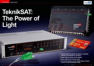
• well thought of system to deliver 4 satellite
signals to hundreds of receivers
• equal signal quality at all outputs
• easy adjustment of gain levels
• terrestrial signal can be added either at basic
unit or at the distribution units
TEST REPORT Optical System
2. 05-06/2015
www.TELE-audiovision.com/15/05/tekniksat
14 15TELE-audiovision International — The World‘s Leading Digital TV Industry Publication — 05-06/2015 — www.TELE-audiovision.com www.TELE-audiovision.com — 05-06/2015 — TELE-audiovision International — 全球发行量最大的数字电视杂志
TEST REPORT Optical System
Fiber optics are used more
and more often when there
is a need to distribute satel-
lite signals to a large number
of receivers. That’s because
fiber optic cables attenuate
signal much less than clas-
sical coaxial cables and add
very little noise to the signal
they convey. It is relatively
easy to find components for
such a system when you
want to distribute the signal
from one chosen satellite.
But if you want to deliver sig-
nals to a high number of re-
ceivers from not one but four
satellites plus a signal from a
terrestrial antenna, the job is
no longer that easy. Time for
Tekniksat Electronics! They
have developed an exten-
sive product portfolio built
around fiber optic distribu-
tion components.
For this test report we de-
cided to build a simple dis-
tribution system and used
these components made by
Tekniksat: TPF 41-2 Opti-
cal Transmitter, TFS 1/32 FC
Splitter and TFM 41/10 C Op-
tical Multiswitch.
The TPF 41-2 Optical
Transmitter is in fact a rack
mounted signal amplifier
and converter. Its job is to
amplify and convert satel-
lite signals coming from 4
different LNBs and 1 terres-
trial input to a single optical
signal. Concerning LNBs, you
can use either Quattro or
Quad LNBs. So, it is easy to
figure out that the TPF 41-2
has 4 x 4 = 16 satellite in-
puts designated with HH, HV,
LH and LV symbols. The 17th
input is for the terrestrial
antenna input, which can be
either an over-the-air recep-
tion like DVB-T/T2 or for con-
necting to a cable system
(DVB-C). Of course, that’s
because terrestrial and cable
TV share the same frequen-
cy band: 47-870 MHz. In this
test report we decided for
connecting the system to a
terrestrial antenna.
The unit provides 23 dB
gain for the satellite signals
and 15 dB gain for the ter-
restrial signal. You can ad-
just each input with a mul-
titurn potentiometer and the
adjustment range is 15 dB.
If needed, you can switch off
the LNB power. If you do not,
then the four LNBs will get
the suitable 13 or 18 V volt-
age for polarization switching
and 22 kHz signal for band
switching from the TPF 41-2.
The TPF 41-2 Optical Trans-
mitter is well finished off and
looks robust and solid. A
cooling fan installed on the
Optical Distribution System
sands of meters and/or split
it to many branches.
In our test we used a 1-to-
32 splitter. Namely it was the
TFS 1/32 FC. The ideal 1-to-
32 splitter would produce at
each output a 1/32 fraction
of the input power. Unfortu-
nately, every practical device
has some additional losses.
In case of the TFS 1/32 FC
those additional losses are
really marginal. The inser-
tion loss is only 16.8 dB
(vs. theoretical 15.05dB).
The splitter itself is a rather
rear panel helps preventing
overheating although during
our tests we did not notice
excessive warming. It may
be useful when the unit is in-
stalled in a cramped 19 inch
cabinet though.
The TPF 41-2 has one SC/
APC optical port and gener-
ates a strong output signal:
4 mW (6dBm). This is the
entry point for the fiber optic
network. With such a strong
signal you can transfer the
signal to very remote loca-
tions: hundreds if not thou-
delicate device, that’s why
Tekniksat as an option also
offers a dedicated rack for it.
To complete the system,
we needed a device located
at the other end of the op-
tic fiber cable – a converter
from light to RF electric
current. We used another
Tekniksat product: the TFM
41/10 C Optical Multiswitch.
Conversely to the optical
transmitter, it has only one
input but many outputs. Of
course, the input is an opti-
cal port and the output are
the F-connectors to which
coax cables are hooked up.
There are no less than 10
subscriber outputs to which
you can directly connect
satellite/terrestrial receiv-
ers. Additionally, there are
16 trunk outputs that regen-
erate the signals from the
four LNBs connected at the
other end of the system. You
can connect classical (coax)
multiswitches to these trunk
output and increase the
number of subscriber out-
puts if needed. There is one
additional input for a ter-
restrial signal that may be
used if this kind of signal is
not originally inserted at the
“top” of the system by the
optical transmitter.
The TFM 41/10 C Optical
Multiswitch has an exter-
nal power supply unit. The
workmanship of the mul-
Optical Distribution System
Perfect to feed hundreds of subscribers with
identical quality signals
3. ■
16 TELE-audiovision International — The World‘s Leading Digital TV Industry Publication — 05-06/2015 — www.TELE-audiovision.com
strong the optical signal will
be. Strength of the signal de-
pends on the split ratio and
attenuation of the optic fiber
cables.
After examining all the
products, it was time to build
a test network. We connect-
ed Quad LNBs to the inputs
of TPF 41-2 Optical Trans-
mitter. At the output of the
transmitter we inserted the
TFS 1/32 FC Splitter and
then routed the optical sig-
nal to the input of the TFM
41/10 C Optical Multiswitch.
We knew very well that there
is little point in adding long
fiber cables between the de-
vices because they add very
little attenuation. The main
sources of attenuation in the
optic networks are the split-
ters and junctions if not kept
clean enough.
To evaluate the whole
system rather than its par-
ticular components, we de-
cided to measure and com-
pare the input signal, i.e.
the one coming from LNBs,
to the output signals avail-
able at the trunk and the
subscriber outputs (S1 and
S10) of the TFM 41/10 C Op-
tical Multiswitch. You can see
the results in two graphs:
one showing signal strength
and the other signal quality.
The first graphs answers the
question whether the sys-
tem has enough gain and the
other – to what extent signal
quality suffers when we split
it and deliver it to 320 sub-
scribers.
The output signal strength
was almost the same as in
the input. For some frequen-
cies/subscriber outputs, it
was slightly lower and for
some others slightly higher
than the input. Please re-
member that the signal has
been split 32 times by the
optical switch and then 10
times by the TFM 41/10 C
Fig. 1 Test setup circuit diagram.
tiswitch itself as well as its
power supply leaves noth-
ing to be desired. They are
clearly labeled and it is re-
ally easy to figure out what
should be connected where.
Everything is obvious at the
first look. The TFM 41/10C
has independent gain ad-
justment of every satellite
and terrestrial output (20
dB range). The adjustment
is really needed because it
is not known a priori how
4. OPINION
EXPERT
+
–
RECOMMENDED
PRODUCT BY
Jacek Pawlowski
Test Center
Poland
TeknikSAT Optical System
TPF 41-2 Optical Transmitter
TFS 1/32 FC Splitter
TFM 41/10 C Optical Multiswitch
18 19TELE-audiovision International — The World‘s Leading Digital TV Industry Publication — 05-06/2015 — www.TELE-audiovision.com www.TELE-audiovision.com — 05-06/2015 — TELE-audiovision International — 全球发行量最大的数字电视杂志
Optical Multiswitch before
it reached a subscriber out-
put. All the gain settings in
the TPF 41-2 and TFM 41/10
C where set to maximum. It
proves that the overall sys-
tem gain is very precisely
calculated and is exactly
as needed for a 1:32 split.
if you built a system for a
lower number of receivers
you would need fewer split-
ting (say, 1:8) and then you
would have to reduce the
gain of the Tekniksat devices
to avoid over driving sub-
scriber receivers.
The second very important
characteristics of the distri-
bution system is its “quiet-
ness” or, in other words, the
● Sufficient gain to deliver the signal to 320 receivers
● Very small impact on signal quality even after splitting it 320
times
● The terrestrial path offers some extra gain what guarantees pro-
blem free DVB-T reception
● None
not much: by 1 dB or so. So,
again very positive results.
One terrestrial antenna will
be enough for 320 receivers.
Should it be a stronger cable
TV signal you can easily ad-
just the gain with a multiturn
potentiometer, either in the
output multiswitch or in the
optical transmitter – just
as for every single satellite
path.
What is also very nice
about this system: you are
not limited to one satellite.
If you connect four different
LNBs receiving signals from
four different satellites, you
can significantly increase the
number of available chan-
nels for each subscriber. You
only need to ensure that the
subscriber receivers have
DiSEqC 1.1 protocol enabling
them to switch among 4 sat-
ellites.
To sum it up, the Tekniksat
fiber optic system proved to
be able to distribute signals
to no less than 320 final sub-
scribers. Additionally, it can
be very easily enlarged be-
cause every final multiswitch
measure how much it spoils
the signal-to-noise param-
eter. Taking into account
that we deal hear with two
signal conversions: electri-
cal to optical and optical to
electrical and additionally
the signal is split firstly in the
optical splitter and secondly
in the final multiswitch, one
could expect a significant
decrease in Modulation Error
Ratio (MER). But, no! Look at
the second graph. Although
there is a small degradation
of signal quality especially in
the lower sub band, the dif-
ference between input and
output is surprisingly low.
You can be pretty sure that if
you have a good signal from
the LNBs, almost equally
good signal will reach each of
the maximal possible num-
ber of 320 receivers.
And that is what we call the
“Power of light”. It is so easy
to achieve such good results
with fiber optic cables when
compared with traditional
electrical splitting.
After so good results with
satellite signals we wanted
to check the terrestrial path.
Our measurements revealed
that the output signal was
stronger by about 15-20 dB
with respect to the input sig-
nal and that signal-to-noise
ratio was again decreased
has trunk outputs to which
classical electrical multi-
switches can be added to
increase even more the total
number of subscribers. It is
a perfect system for hotels
and similar facilities where
you need to keep the num-
ber of antennas to an abso-
lute minimum and the num-
ber of receivers is very high.
Most of all: you can be sure
that with this system you get
the same signal quality at all
outputs.