ABB High Voltage Current Limiting Fuse Links Type CEF - ABB Indoor Medium Voltage MV Fuses
•
1 recomendación•3,261 vistas

ABB High Voltage Current Limiting Fuse Links Type CEF - ABB Indoor Medium Voltage MV Fuses
![Fuses 9
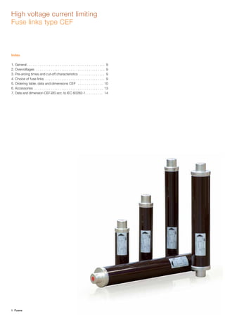
Rated voltage: 3.6/7.2-36 kV
High voltage current limiting Fuse links type CEF
1. General
The HRC generation of fuse links type CEF is designed and tested
according to IEC Publication 60282-1 (IEC 282-1). Dimensionally
the fuse links are in accordance with DIN 43625. There are avail-
able CEF fuses marked as E-Rated. The detailed information are
published in separate publication. ABB’s high-voltage fuse-
-links have the following properties:
– unified voltage ratings for more application flexibility,
– integrated striker pin with temperature control unit (TCU) to prevent
overheating in installation place,
– overload spots control internal arc initiation and determine out-
standing temperature performance,
– single fuse version for both indoor and outdoor operating condi-
tions,
– narrow tolerance of resistance for better fuse synchronizing in three
phase networks,
– graved fuse data for long term fuse recognition,
– welded current path secures stable electrical contacts with active
breaking elements low minimum breaking current,
– high breaking capacity in combination with fuse tripped load break
switch offers competitive solution for short circuit currents interruption,
– low power losses make fuses suitable for compact switchgear and
ring main units,
– high current limitation significantly reduce prospective value of short
circuit currents and therefore extends insulation live time,
– type tested acc. to IEC 60282-1.
CEF fuses are of a back-up type. They have a zone between the
minimum melting current and the minimum breaking current where
the fuse links may fail to interrupt. For CEF fuse links this zone is very
narrow. The minimum breaking current, I3, for any type is specified in
the table on pages 10 to 12.
20
30
40
50
60
70
80
90
100
200
300
400
500
600
700
800
9001000
2000
3000
4000
5000
6000
7000
8000
900010000
0.01
0.02
0.04
0.06
0.08
0.1
0.2
0.4
0.6
0.8
1
2
4
6
8
10
20
40
60
80
100
200
400
600
800
1000
2000
4000
6A
200A200A
160A
125A
100A
80A
63A
50A
40A
31.5A
20A
16A
10A
25A
0,1
1
10
100
0,1 1 10 100
Prospective short circuit current Irms [kA]
Maximumcut-offcurrentIpeak[kA]
6A
10A
16A
20A
25A
31,5A
40A
50A
63A
80A
100A
125A
160A
200A
4. Choice of fuse links
Choice of rated current In
In order to choose the current fuse link rated current for trans-
former protection, the relation between the power rating of the
transformers, and the operating voltage and rated current of the
fuse link is given in the table on page 10.
For the correct choice of fuse links for transformer protection in
switchgear type SafeRing, SafePlus and SafeLink, see SF6 Insu-
lation Compact Switchgear and Ring Main Unit catalogue.
Remarks:
1. Characteristics show the average melting time as a function of the prospective current.
2. The deviation of 10% refers to the current.
3. The characteristics are valid for all rated voltages and are recorded from fuse link cold condition.
4. Broken line indicates the uncertain interrupting zone.
2. Overvoltages
In order to be current limiting, the fuse link must generate an arc volt-
age that exceeds the instantaneous value of the operating voltage.
The switching voltage generated by the CEF fuse link is below the
maximum permissible value according to IEC 60282-1 (IEC 282-1).
The CEF fuse link can safely be used within voltage range presented
in fuse name (i.e. 10/24 kV means that the fuse may be safety used
between 10 kV and 24 kV) please see rated voltage allowable ratings
in fuse label area.
3. Pre-arcing times and cut-off characteristics
The characteristics are equal for all rated voltages and are recorded
under cold conditions. Dashed sections of the curves indicate an
area of uncertain interruption. The tolerance is 10% and it refers to
the current.](data:image/gif;base64,R0lGODlhAQABAIAAAAAAAP///yH5BAEAAAAALAAAAAABAAEAAAIBRAA7)
Recomendados
Recomendados
Más contenido relacionado
La actualidad más candente
La actualidad más candente (18)
Similar a ABB High Voltage Current Limiting Fuse Links Type CEF - ABB Indoor Medium Voltage MV Fuses
Similar a ABB High Voltage Current Limiting Fuse Links Type CEF - ABB Indoor Medium Voltage MV Fuses (20)
Más de Thorne & Derrick International
Más de Thorne & Derrick International (20)
Último
Último (20)
ABB High Voltage Current Limiting Fuse Links Type CEF - ABB Indoor Medium Voltage MV Fuses
- 1. 8 Fuses High voltage current limiting Fuse links type CEF Index 1. General . . . . . . . . . . . . . . . . . . . . . . . . . . . . . . . . . . . . . . . . . . . 9 2. Overvoltages . . . . . . . . . . . . . . . . . . . . . . . . . . . . . . . . . . . . . . 9 3. Pre-arcing times and cut-off characteristics . . . . . . . . . . . . . . 9 4. Choice of fuse links . . . . . . . . . . . . . . . . . . . . . . . . . . . . . . . . . 9 5. Ordering table, data and dimensions CEF . . . . . . . . . . . . . . 10 6. Accessories . . . . . . . . . . . . . . . . . . . . . . . . . . . . . . . . . . . . . . 13 7. Data and dimension CEF-BS acc. to IEC 60282-1. . . . . . . . . . 14
- 2. Fuses 9 Rated voltage: 3.6/7.2-36 kV High voltage current limiting Fuse links type CEF 1. General The HRC generation of fuse links type CEF is designed and tested according to IEC Publication 60282-1 (IEC 282-1). Dimensionally the fuse links are in accordance with DIN 43625. There are avail- able CEF fuses marked as E-Rated. The detailed information are published in separate publication. ABB’s high-voltage fuse- -links have the following properties: – unified voltage ratings for more application flexibility, – integrated striker pin with temperature control unit (TCU) to prevent overheating in installation place, – overload spots control internal arc initiation and determine out- standing temperature performance, – single fuse version for both indoor and outdoor operating condi- tions, – narrow tolerance of resistance for better fuse synchronizing in three phase networks, – graved fuse data for long term fuse recognition, – welded current path secures stable electrical contacts with active breaking elements low minimum breaking current, – high breaking capacity in combination with fuse tripped load break switch offers competitive solution for short circuit currents interruption, – low power losses make fuses suitable for compact switchgear and ring main units, – high current limitation significantly reduce prospective value of short circuit currents and therefore extends insulation live time, – type tested acc. to IEC 60282-1. CEF fuses are of a back-up type. They have a zone between the minimum melting current and the minimum breaking current where the fuse links may fail to interrupt. For CEF fuse links this zone is very narrow. The minimum breaking current, I3, for any type is specified in the table on pages 10 to 12. 20 30 40 50 60 70 80 90 100 200 300 400 500 600 700 800 9001000 2000 3000 4000 5000 6000 7000 8000 900010000 0.01 0.02 0.04 0.06 0.08 0.1 0.2 0.4 0.6 0.8 1 2 4 6 8 10 20 40 60 80 100 200 400 600 800 1000 2000 4000 6A 200A200A 160A 125A 100A 80A 63A 50A 40A 31.5A 20A 16A 10A 25A 0,1 1 10 100 0,1 1 10 100 Prospective short circuit current Irms [kA] Maximumcut-offcurrentIpeak[kA] 6A 10A 16A 20A 25A 31,5A 40A 50A 63A 80A 100A 125A 160A 200A 4. Choice of fuse links Choice of rated current In In order to choose the current fuse link rated current for trans- former protection, the relation between the power rating of the transformers, and the operating voltage and rated current of the fuse link is given in the table on page 10. For the correct choice of fuse links for transformer protection in switchgear type SafeRing, SafePlus and SafeLink, see SF6 Insu- lation Compact Switchgear and Ring Main Unit catalogue. Remarks: 1. Characteristics show the average melting time as a function of the prospective current. 2. The deviation of 10% refers to the current. 3. The characteristics are valid for all rated voltages and are recorded from fuse link cold condition. 4. Broken line indicates the uncertain interrupting zone. 2. Overvoltages In order to be current limiting, the fuse link must generate an arc volt- age that exceeds the instantaneous value of the operating voltage. The switching voltage generated by the CEF fuse link is below the maximum permissible value according to IEC 60282-1 (IEC 282-1). The CEF fuse link can safely be used within voltage range presented in fuse name (i.e. 10/24 kV means that the fuse may be safety used between 10 kV and 24 kV) please see rated voltage allowable ratings in fuse label area. 3. Pre-arcing times and cut-off characteristics The characteristics are equal for all rated voltages and are recorded under cold conditions. Dashed sections of the curves indicate an area of uncertain interruption. The tolerance is 10% and it refers to the current.
- 3. 10 Fuses Transfor- mer rated voltage [kV] Transformer rating [kVA] Fuse rated voltage [kV] 25 50 75 100 125 160 200 250 315 400 500 630 800 1000 1250 1600 2000 2500 3000 3500 CEF Fuse link In [A] 3 16 25 25 40 40 50 63 80 100 125 160 200 2501) 3151) 2x2501) 2x3151) 3/7.25 10 16 25 25 25 40 40 50 63 80 100 125 160 200 2501) 3151) 2x2501) 2x3151) 6 6 16 16 25 25 25 40 40 50 63 80 100 125 160 200 2501) 3151) 2x2501) 2x3151) 10 6 10 16 16 16 20 20 25 31.5 40 50 63 80 100 125 160 200 2x160 2x200 2x200 6/12 12 6 6 10 16 16 16 20 20 25 40 40 50 63 80 100 125 160 200 2x160 2x200 15 6 6 10 10 16 16 16 20 20 25 40 40 50 63 80 100 125 2x100 2x125 10/17.5 20 6 6 6 10 10 16 16 16 20 20 25 31.5 40 50 63 80 100 125 2x100 2x100 10/24 24 6 6 6 6 10 10 16 16 16 20 20 25 40 40 50 63 80 100 125 2x100 30 6 6 6 6 6 10 10 16 16 16 25 25 25 40 40 2x25 2x40 20/36 36 6 6 6 6 6 10 10 10 16 16 25 25 25 40 40 2x25 2x40 2x40 1) CMF fuse link The table was calculated according to standards IEC 60787 and IEC 62271-105. The following transformer work conditions were assumed: – maximum long-lasting overload – 150%, – magnetizing inrush current – 12xIn during 100 ms, – transformer short-circuit voltage according to IEC 60076-5, – standard ambient working conditions of fuses. Choice of fuse links for transformer protection 5. Ordering table, data and dimensions CEF New smartcode CEF In [A] I1 [kA] I3 [A] Pn [W] Pre-arcing integral I2 t [A2 s] Operating integral I2 t [A2 s] R0 [mΩ] D [mm] Weight [kg] Old catalogue No. CEF Old catalogue No. CEF-TCU Rated voltage: 3/7.2 kV Length "e": 192 mm 1YMB710713M1611 6 50 35 26 20 300 460.00 65 1.5 1YMB531001M0001 1YMB531851M0001 1YMB710716M1611 10 50 55 16 30 500 120.30 65 1.5 1YMB531001M0002 1YMB531851M0002 1YMB710718M1611 16 50 55 26 120 2000 60.20 65 1.5 1YMB531001M0003 1YMB531851M0003 1YMB710721M1611 25 50 72 24 500 7000 30.10 65 1.5 1YMB531001M0004 1YMB531851M0004 1YMB710725M1611 40 50 100 30 1000 20000 15.30 65 1.5 1YMB531001M0005 1YMB531851M0005 1YMB710727M1611 50 50 190 35 2500 31000 10.40 65 1.5 1YMB531001M0006 1YMB531851M0006 1YMB710729M1611 63 50 190 40 4500 90000 7.80 65 1.5 1YMB531001M0007 1YMB531851M0007 1YMB710731M1811 80 50 250 52 9200 78000 6.20 87 2.6 1YMB531001M0008 1YMB531851M0008 1YMB710733M1811 100 50 275 57 15000 300000 4.40 87 2.6 1YMB531001M0009 1YMB531851M0009 Rated voltage: 3/7.2 kV Length "e": 292 mm 1YMB710713M2611 6 50 35 26 20 300 460.00 65 2.3 1YMB531034M0001 1YMB531884M0001 1YMB710716M2611 10 50 55 16 30 500 120.30 65 2.3 1YMB531034M0002 1YMB531884M0002 1YMB710718M2611 16 50 55 26 120 2000 60.20 65 2.3 1YMB531034M0003 1YMB531884M0003 1YMB710721M2611 25 50 72 24 500 7000 30.10 65 2.3 1YMB531034M0004 1YMB531884M0004 1YMB710725M2611 40 50 100 30 1000 20000 15.30 65 2.3 1YMB531034M0005 1YMB531884M0005 1YMB710727M2611 50 50 190 35 2500 31000 10.40 65 2.3 1YMB531034M0006 1YMB531884M0006 1YMB710729M2611 63 50 190 40 4500 90000 7.80 65 2.3 1YMB531034M0007 1YMB531884M0007 1YMB710731M2811 80 50 250 52 9200 78000 6.20 87 3.6 1YMB531034M0008 1YMB531884M0008 1YMB710733M2811 100 50 275 57 15000 300000 4.40 87 3.6 1YMB531034M0009 1YMB531884M0009 1YMB710735M2811 125 50 375 76 20000 400000 3.50 87 3.6 1YMB531001M0010 1YMB531851M0010 1YMB710738M2811 160 50 480 101 35000 600000 2.60 87 3.6 1YMB531001M0011 1YMB531851M0011 1YMB710739M2811 200 50 650 107 100000 900000 1.70 87 3.6 1YMB531001M0012 1YMB531851M0012 Rated voltage: 3/7.2 kV Length „e”: 367 mm 1YMB710735M3811 125 50 375 76 20000 400000 3.5 87 4.4 1YMB531034M1010 1YMB531884M1010 1YMB710738M3811 160 50 480 101 35000 600000 2.6 87 4.4 1YMB531034M0011 1YMB531884M0011 1YMB710739M3811 200 50 650 107 100000 900000 1.7 87 4.4 1YMB531034M0012 1YMB531884M0012 Rated voltage: 6/12 kV Length "e": 292 mm 1YMB711213M2511 6 63 36 46 20 300 665.0 53 1.9 1YMB531042M0001 1YMB531892M0001 1YMB711213M2611 6 63 35 41 20 300 665.0 65 2.3 1YMB531002M0001 1YMB531852M0001 1YMB711216M2511 10 63 65 25 30 500 180.5 53 1.9 1YMB531042M0002 1YMB531892M0002 1YMB711216M2611 10 63 55 33 30 500 180.5 65 2.3 1YMB531002M0002 1YMB531852M0002 1YMB711218M2511 16 63 65 34 120 2000 105.2 53 1.9 1YMB531042M0003 1YMB531892M0003 The table above details the rated current of a particular fuse link for a given line voltage and transformer rating. For different crite- ria, the fuse selection must be recalculated.
- 4. Fuses 11 Rated voltage: 6/12 kV Length „e”: 292 mm 1YMB711218M2611 16 63 55 32 120 2000 105.2 65 2.3 1YMB531002M0003 1YMB531852M0003 1YMB711219M2511 20 63 83 38 365 5600 70.1 53 1.9 1YMB531042M0004 1YMB531892M0004 1YMB711221M2611 25 63 77 47 500 7000 52.6 65 2.3 1YMB531002M0004 1YMB531852M0004 1YMB711225M2611 40 63 105 52 1000 20000 23.0 65 2.3 1YMB531002M0005 1YMB531852M0005 1YMB711227M2611 50 63 190 70 2500 31000 17.9 65 2.3 1YMB531002M0006 1YMB531852M0006 1YMB711229M2611 63 63 190 78 4500 90000 13.4 65 2.3 1YMB531002M0007 1YMB531852M0007 1YMB711231M2811 80 63 250 82 9200 78000 9.2 87 3.6 1YMB531002M0008 1YMB531852M0008 1YMB711233M2811 100 63 275 84 15000 300000 6.6 87 3.6 1YMB531002M0009 1YMB531852M0009 1YMB711224M2611 31.5 63 100 41 610 12100 30.7 65 2.3 1YMB531002M0014 1YMB531852M0014 1YMB711231M2611 80 63 250 82 9200 78000 9.2 65 2.3 1YMB531002M0021 1YMB531852M0021 1YMB711233M2611 100 63 375 101 15000 300000 6.4 65 2.3 1YMB531002M0022 1YMB531852M0022 1YMB711235M2811 125 63 375 125 20000 400000 5.3 87 3.6 1YMB531043M0010 1YMB531893M0010 Rated voltage: 6/12 kV Length „e”: 442 mm 1YMB711213M4511 6 63 36 46 20 300 665.0 53 2.5 1YMB531047M0001 1YMB531897M0001 1YMB711213M4611 6 63 35 41 20 300 665.0 65 3 1YMB531035M0001 1YMB531885M0001 1YMB711216M4511 10 63 65 25 30 500 180.5 53 2.5 1YMB531047M0002 1YMB531897M0002 1YMB711216M4611 10 63 55 33 30 500 180.5 65 3 1YMB531035M0002 1YMB531885M0002 1YMB711218M4511 16 63 65 34 120 2000 105.2 53 2.5 1YMB531047M0003 1YMB531897M0003 1YMB711218M4611 16 63 55 32 120 2000 105.2 65 3 1YMB531035M0003 1YMB531885M0003 1YMB711219M4511 20 63 83 38 365 5600 70.1 53 2.5 1YMB531047M0004 1YMB531897M0004 1YMB711221M4611 25 63 77 47 500 7000 52.6 65 3 1YMB531035M0004 1YMB531885M0004 1YMB711224M4611 31.5 63 100 41 610 12100 30.7 65 3 1YMB531035M0014 1YMB531885M0014 1YMB711225M4611 40 63 105 52 1000 20000 23.0 65 3 1YMB531035M0005 1YMB531885M0005 1YMB711227M4611 50 63 190 70 2500 31000 17.9 65 3 1YMB531035M0006 1YMB531885M0006 1YMB711229M4611 63 63 190 78 4500 90000 13.4 65 3 1YMB531035M0007 1YMB531885M0007 1YMB711231M4611 80 63 250 82 9200 78000 9.2 65 3 1YMB531035M0021 1YMB531885M0021 1YMB711231M4811 80 63 250 82 9200 78000 9.2 87 5.3 1YMB531035M0008 1YMB531885M0008 1YMB711233M4611 100 63 375 103 15000 300000 6.4 65 3 1YMB531035M0022 1YMB531885M0022 1YMB711233M4811 100 63 275 84 15000 300000 6.6 87 5.3 1YMB531035M0009 1YMB531885M0009 1YMB711235M4611 125 63 375 125 20000 400000 5.3 65 3 1YMB531002M0023 1YMB531852M0023 1YMB711235M4811 125 63 375 125 20000 400000 5.3 87 5.3 1YMB531002M0010 1YMB531852M0010 1YMB711238M4811 160 63 480 170 35000 600000 3.9 87 5.3 1YMB531002M0011 1YMB531852M0011 1YMB711239M4811 200 50 650 174 100000 900000 2.7 87 5.3 1YMB531002M0012 1YMB531852M0012 Rated voltage: 6/12 kV Length „e”: 537 mm 1YMB711235M5611 125 50 375 125 20000 400000 5.3 65 4 1YMB531035M0023 1YMB531885M0023 1YMB711235M5811 125 50 375 125 20000 400000 5.3 87 5.3 1YMB531035M0010 1YMB531885M0010 1YMB711238M5811 160 50 480 170 35000 600000 3.9 87 5.3 1YMB531035M0011 1YMB531885M0011 1YMB711239M5811 200 50 650 174 100000 900000 2.7 87 5.3 1YMB531035M0012 1YMB531885M0012 Rated voltage: 10/17.5 kV Length "e": 292 mm 1YMB711713M2611 6 20 35 54 20 300 807.0 65 2.3 1YMB531003M0001 1YMB531853M0001 1YMB711716M2611 10 20 55 41 30 500 270.7 65 2.3 1YMB531003M0002 1YMB531853M0002 1YMB711718M2611 16 20 55 67 120 2000 135.4 65 2.3 1YMB531003M0003 1YMB531853M0003 1YMB711719M2611 20 25 83 52.6 365 5600 90.3 65 2.3 1YMB531003M0013 1YMB531853M0013 1YMB711721M2611 25 25 72 64 500 7000 67.7 65 2.3 1YMB531003M0004 1YMB531853M0004 1YMB711724M2611 31.5 25 100 56.7 610 12100 46.0 65 2.3 1YMB531003M0014 1YMB531853M0014 1YMB711725M2611 40 25 210 80 1000 20000 34.7 65 2.3 1YMB531003M0021 1YMB531853M0021 1YMB711725M2811 40 25 100 80 1000 20000 34.5 87 3.6 1YMB531003M0005 1YMB531853M0005 1YMB711727M2611 50 25 210 90 2500 31000 23.1 65 2.3 1YMB531003M0022 1YMB531853M0022 1YMB711727M2811 50 25 210 90 2500 31000 23.1 87 3.6 1YMB531003M0006 1YMB531853M0006 1YMB711729M2811 63 25 210 100 4500 90000 17.3 87 3.6 1YMB531003M0007 1YMB531853M0007 Rated voltage: 10/17.5 kV Length "e": 367 mm 1YMB711713M3611 6 20 35 54 20 300 807.0 65 2.7 1YMB531036M0001 1YMB531886M0001 1YMB711716M3611 10 20 55 41 30 500 270.7 65 2.7 1YMB531036M0002 1YMB531886M0002 1YMB711718M3611 16 20 55 67 120 2000 135.4 65 2.7 1YMB531036M0003 1YMB531886M0003 1YMB711719M3611 20 25 83 52.6 365 5600 90.3 65 2.7 1YMB531036M0013 1YMB531886M0013 1YMB711721M3611 25 25 72 64 500 7000 67.7 65 2.7 1YMB531036M0004 1YMB531886M0004 1YMB711724M3611 31.5 25 100 56.7 610 12100 46.0 65 2.7 1YMB531036M0014 1YMB531886M0014 1YMB711725M3611 40 25 210 80 1000 20000 34.7 65 2.7 1YMB531036M0021 1YMB531886M0021 1YMB711725M3811 40 25 100 80 1000 20000 34.5 87 4.4 1YMB531036M0005 1YMB531886M0005 1YMB711727M3611 50 25 210 90 2500 31000 23.1 65 2.7 1YMB531036M0022 1YMB531886M0022 1YMB711727M3811 50 25 210 90 2500 31000 23.1 87 4.4 1YMB531036M0006 1YMB531886M0006 1YMB711729M3811 63 25 210 100 4500 90000 17.3 87 4.4 1YMB531036M0007 1YMB531886M0007 1YMB711733M3811 100 25 375 136 15000 300000 9.5 87 4.4 1YMB531038M0001 1YMB531888M0001 New smartcode CEF In [A] I1 [kA] I3 [A] Pn [W] Pre-arcing integral I2 t [A2 s] Operating integral I2 t [A2 s] R0 [mΩ] D [mm] Weight [kg] Old catalogue No. CEF Old catalogue No. CEF-TCU
- 5. 12 Fuses Legend: In – rated current I1 – rated maximum breaking current I3 – rated minimum breaking current Pw – rated power Ro – resistance D – diameter Remark: Above table is for reference purpose and is not commercial offer. The present technical data and product availability information should be obtained from our sales representatives. Rated voltage: 10/17.5 kV Length „e”: 442 mm 1YMB711713M4611 6 20 35 54 20 300 807.0 65 3 1YMB531037M0001 1YMB531887M0001 1YMB711716M4611 10 20 55 41 30 500 270.7 65 3 1YMB531037M0002 1YMB531887M0002 1YMB711718M4611 16 20 55 67 120 2000 135.4 65 3 1YMB531037M0003 1YMB531887M0003 1YMB711719M4611 20 25 83 52.6 365 5600 90.3 65 3 1YMB531037M0013 1YMB531887M0013 1YMB711721M4611 25 25 72 64 500 7000 67.7 65 3 1YMB531037M0004 1YMB531887M0004 1YMB711724M4611 31.5 25 100 56.7 610 12100 46.0 65 3 1YMB531037M0014 1YMB531887M0014 1YMB711725M4611 40 25 210 80 1000 20000 34.7 65 3 1YMB531037M0021 1YMB531887M0021 1YMB711725M4811 40 25 100 80 1000 20000 34.5 87 5.3 1YMB531037M0005 1YMB531887M0005 1YMB711727M4611 50 25 210 90 2500 31000 23.1 65 3 1YMB531037M0022 1YMB531887M0022 1YMB711727M4811 50 25 210 90 2500 31000 23.1 87 5.3 1YMB531037M0006 1YMB531887M0006 1YMB711729M4811 63 25 210 100 4500 90000 17.3 87 5.3 1YMB531037M0007 1YMB531887M0007 1YMB711731M4811 80 25 250 124 9200 78000 13.8 87 5.3 1YMB531003M0008 1YMB531853M0008 1YMB711733M4811 100 25 275 136 15000 300000 9.9 87 5.3 1YMB531003M0009 1YMB531853M0009 Rated voltage: 10/17.5 kV Length "e": 537 mm 1YMB711731M5811 80 25 250 124 9200 78000 13.8 87 5.3 1YMB531037M0008 1YMB531887M0008 1YMB711733M5811 100 25 275 136 15000 300000 9.9 87 5.3 1YMB531037M0009 1YMB531887M0009 1YMB711735M5811 125 25 375 175 20000 400000 7.9 87 5.3 1YMB531037M0010 1YMB531887M0010 Rated voltage: 10/24 kV Length „e”: 442 mm 1YMB712413M4511 6 63 25 82 20 300 1229.0 53 2.5 1YMB531044M0001 1YMB531894M0001 1YMB712413M4611 6 63 35 91 20 300 1229.0 65 3 1YMB531004M0001 1YMB531854M0001 1YMB712416M4511 10 63 65 48 30 500 360.9 53 2.5 1YMB531044M0002 1YMB531894M0002 1YMB712416M4611 10 63 55 62 30 500 360.9 65 3 1YMB531004M0002 1YMB531854M0002 1YMB712418M4511 16 63 65 63 120 2000 180.5 53 2.5 1YMB531044M0003 1YMB531894M0003 1YMB712418M4611 16 63 55 72 120 2000 180.5 65 3 1YMB531004M0003 1YMB531854M0003 1YMB712419M4511 20 63 83 64 365 5600 120.3 53 2.5 1YMB531044M0004 1YMB531894M0004 1YMB712419M4611 20 63 82 61 365 5600 120.3 65 3 1YMB531004M0011 1YMB531854M0011 1YMB712421M4611 25 63 72 79 500 7000 90.2 65 3 1YMB531004M0004 1YMB531854M0004 1YMB712424M4611 31.5 63 82 98 610 12100 72.2 65 3 1YMB531004M0012 1YMB531854M0012 1YMB712425M4611 40 63 110 106 1000 20000 46.0 65 3 1YMB531004M0005 1YMB531854M0005 1YMB712427M4611 50 63 210 130 2500 31000 30.7 65 3 1YMB531004M0021 1YMB531854M0021 1YMB712427M4811 50 63 210 130 2500 31000 30.7 87 5.3 1YMB531004M0006 1YMB531854M0006 1YMB712429M4611 63 63 250 147 4500 90000 23.0 65 3 1YMB531004M0022 1YMB531854M0022 1YMB712429M4811 63 63 210 147 4500 90000 23.0 87 5.3 1YMB531004M0007 1YMB531854M0007 1YMB712431M4811 80 63 250 165 9200 78000 18.4 87 5.3 1YMB531022M0001 1YMB531872M0001 Rated voltage: 10/24 kV Length „e”: 537 mm 1YMB712431M5611 80 63 250 165 9200 78000 18.4 65 4 1YMB531004M0023 1YMB531854M0023 1YMB712431M5811 80 63 250 165 9200 78000 18.4 87 6.2 1YMB531004M0008 1YMB531854M0008 1YMB712433M5811 100 63 300 186 15000 300000 13.2 87 6.2 1YMB531004M0009 1YMB531854M0009 1YMB712435M5811 125 63 375 234 20000 400000 10.5 87 6.2 1YMB531004M0010 1YMB531854M0010 Rated voltage: 27 kV Length „e”: 442 mm 1YMB712713M4611 6 20 35 91 20 300 1295.0 65 3 1YMB531005M0001 1YMB531855M0001 1YMB712716M4611 10 20 55 80 30 500 451.2 65 3 1YMB531005M0002 1YMB531855M0002 1YMB712718M4611 16 20 55 90 120 2000 225.6 65 3 1YMB531005M0003 1YMB531855M0003 1YMB712721M4811 25 20 72 100 500 7000 112.8 87 3 1YMB531005M0004 1YMB531855M0004 1YMB712725M4811 40 20 110 130 1000 20000 55.6 87 3 1YMB531005M0005 1YMB531855M0005 1YMB712727M4811 50 20 210 130 2500 20000 30.7 87 5.3 1YMB531005M0006 1YMB531855M0006 1YMB712729M4811 63 20 210 147 4500 20000 23.0 87 5.3 1YMB531005M0007 1YMB531855M0007 Rated voltage: 27 kV Length "e": 537 mm 1YMB712731M5811 80 20 250 210 9200 20000 18.4 87 5.3 1YMB531005M0008 1YMB531855M0008 Rated voltage: 20/36 kV Length "e": 537 mm 1YMB713613M5611 6 20 35 137 20 300 1860.0 65 4 1YMB531006M0001 1YMB531856M0001 1YMB713616M5611 10 20 55 93 30 500 571.5 65 4 1YMB531006M0002 1YMB531856M0002 1YMB713618M5611 16 20 55 109 120 2000 285.8 65 4 1YMB531006M0003 1YMB531856M0003 1YMB713621M5811 25 20 72 144 500 7000 142.9 87 6.2 1YMB531006M0004 1YMB531856M0004 1YMB713625M5811 40 20 100 176 1000 20000 69.1 87 6.2 1YMB531006M0005 1YMB531856M0005 New smartcode CEF In [A] I1 [kA] I3 [A] Pn [W] Pre-arcing integral I2 t [A2 s] Operating integral I2 t [A2 s] R0 [mΩ] D [mm] Weight [kg] Old catalogue No. CEF Old catalogue No. CEF-TCU
- 6. Fuses 13 6. Accessories Fuse bases type UCE (suitable for CEF, CEF-S, CEF-VT fuses) Fuse clips Cat. No. 1YMX000128M0001 60 27 32 Type Rated voltage Rated current Fuse length Dimensions in mm Weight Catalogue No. Un [kV] In [A] [mm] A A1 A2 H K K1 B [kg] UCE 7.2 3.6/7.2 6-100 192 242 160 221 310 218 193 55 3.4 1YMX052501M0001 UCE12 3.6/12 6-200 292 242 160 221 410 318 293 180 3.7 1YMX052503M0001 UCE 12L 12 125-200 442 242 160 221 570 468 443 300 4.2 1YMX052505M0001 UCE 17.5 17.5 6-63 292 327 245 306 410 318 293 180 3.7 1YMX052507M0001 UCE 24 24 6-125 292 327 245 306 410 318 293 180 3.7 1YMX052508M0001 UCE 24 17.5/24 6-125 442 327 245 306 570 468 443 300 6.9 1YMX052509M0001 UCE 24L 24 80-125 537 327 245 306 675 563 538 380 7.4 1YMX052511M0001 UCE 36 36 6-40 537 422 340 401 675 563 538 380 7.6 1YMX052513M0001 Catalogue No. Weight [kg] Dimension in mm e*) Total lenght 1YMX300062M0001 1.4 192 292 442 537 605 *) Adjustable The striker has a force-travel characteristic as shown in the figure on page 7. Operating tong for fuse links CEF 3.6/7.2 – 36 kV Catalogue No. Test voltage [kV] Weight [kg] 1YMX053006M0001 75 2.59 Dimensions in mm Clamping range 50 ... 90 mm Total length (lG) 1500 mm Insulating clearance (lI) 525 mm Length (handle) (IH) 780 mm Insertion depth (IO) 195 mm CEF test fuse link 3.6/7.2-40.5 kV for test of striker system
- 7. 14 Fuses 7. Data and dimension CEF-BS acc. To IEC 60282-1:1996 Type Rated voltage Un [kV] Rated current In [A] L/D [mm] A/d [mm] Catalogue No. EAN13 Codes CEF-BS-B 3,6/7,2 6 305/65 340/40 1YMB531007M0021 5901436020844 CEF-BS-B 3,6/7,2 10 305/65 340/40 1YMB531007M0022 5901436020851 CEF-BS-B 3,6/7,2 16 305/65 340/40 1YMB531007M0023 5901436020868 CEF-BS-B 3,6/7,2 25 305/65 340/40 1YMB531007M0024 5901436020875 CEF-BS-B 3,6/7,2 40 305/65 340/40 1YMB531007M0025 5901436020882 CEF-BS-B 3,6/7,2 50 305/65 340/40 1YMB531007M0026 5901436020899 CEF-BS-B 3,6/7,2 63 305/65 340/40 1YMB531007M0027 5901436020905 CEF-BS-B 3,6/7,2 80 305/87 340/40 1YMB531007M0028 5901436020912 CEF-BS-B 3,6/7,2 100 305/87 340/40 1YMB531007M0029 5901436020929 CEF-BS-D 3,6/7,2 125 419/87 461/50,5 1YMB531007M0030 5901436020936 CEF-BS-D 3,6/7,2 160 419/87 461/50,5 1YMB531007M0031 5901436020943 CEF-BS-D 3,6/7,2 200 419/87 461/50,5 1YMB531007M0032 5901436020950 CEF-BS-D 12 6 419/65 461/50,5 1YMB531008M0021 5901436021292 CEF-BS-D 12 10 419/65 461/50,5 1YMB531008M0022 5901436021308 CEF-BS-D 12 16 419/65 461/50,5 1YMB531008M0023 5901436021315 CEF-BS-D 12 25 419/65 461/50,5 1YMB531008M0024 5901436021322 CEF-BS-D 12 40 419/65 461/50,5 1YMB531008M0025 5901436021339 CEF-BS-D 12 50 419/65 461/50,5 1YMB531008M0026 5901436021346 CEF-BS-D 12 63 419/65 461/50,5 1YMB531008M0027 5901436021353 CEF-BS-D 12 80 419/87 461/50,5 1YMB531008M0028 5901436021360 CEF-BS-D 12 100 419/87 461/50,5 1YMB531008M0029 5901436021377 CEF-BS-B 12 125 553/87 590/40 1YMB531008M0030 5901436021384 CEF-BS-B 12 160 553/87 590/40 1YMB531008M0031 5901436021391 CEF-BS-B 12 200 553/87 590/40 1YMB531008M0032 5901436021407 CEF-BS-D 17,5 6 419/65 461/50,5 1YMB531009M0021 5901436021605 CEF-BS-D 17,5 10 419/65 461/50,5 1YMB531009M0022 5901436021612 CEF-BS-D 17,5 16 419/65 461/50,5 1YMB531009M0023 5901436021629 CEF-BS-D 17,5 25 419/65 461/50,5 1YMB531009M0024 5901436021636 CEF-BS-D 17,5 40 419/87 461/50,5 1YMB531009M0025 5901436021643 CEF-BS-D 17,5 50 419/87 461/50,5 1YMB531009M0026 5901436021650 CEF-BS-D 17,5 63 419/87 461/50,5 1YMB531009M0027 5901436021667 CEF-BS-B 17,5 80 553/87 590/40 1YMB531009M0028 5901436021674 CEF-BS-B 17,5 100 553/87 590/40 1YMB531009M0029 5901436021681 CEF-BS-B 24 6 553/65 590/40 1YMB531010M0021 5901436021841 CEF-BS-B 24 10 553/65 590/40 1YMB531010M0022 5901436021858 CEF-BS-B 24 16 553/65 590/40 1YMB531010M0023 5901436021865 CEF-BS-B 24 25 553/65 590/40 1YMB531010M0024 5901436021872 CEF-BS-B 24 40 553/65 590/40 1YMB531010M0025 5901436021889 CEF-BS-B 24 50 553/87 590/40 1YMB531010M0026 5901436021896 CEF-BS-B 24 63 553/87 590/40 1YMB531010M0027 5901436021902 Remark: BS styles are available on request only. Dimension CEF-BS-B Dimension CEF-BS-D