Roxtec R Cable Transit Frame - Installation Instructions
•
1 recomendación•503 vistas

Roxtec R Cable Transit Frame - Installation Instructions

Recomendados
Recomendados
Más contenido relacionado
Destacado
Destacado (7)
Similar a Roxtec R Cable Transit Frame - Installation Instructions
Similar a Roxtec R Cable Transit Frame - Installation Instructions (20)
Más de Thorne & Derrick International
Más de Thorne & Derrick International (20)
Último
Último (20)
Roxtec R Cable Transit Frame - Installation Instructions
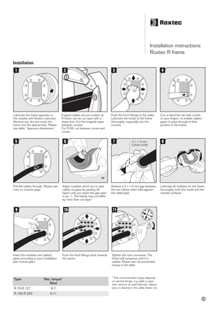
- 1. Installation instructions Roxtec R frame Installation 0.1–1.0 mm 0.004-0.039” Lubricate the frame sparsely on the outside with Roxtec Lubricant. Remove any dirt and insert the frame into the sleeve/hole. Please see table “Aperture dimensions”. Push the front fittings to the sides. Lubricate the inside of the frame thoroughly, especially into the corners. Cut or bend the net with a knife, or your fingers, to enable cables/ pipes to pass through at their position in the frame. Pull the cables through. Please see note on reverse page. Achieve a 0.1-1.0 mm gap between the two halves when held against the cable/pipe. Lubricate all modules for the frame thoroughly, both the inside and the outside surfaces. Adapt modules which are to seal cables or pipes by peeling off layers until you reach the gap seen in pic. 7. The halves may not differ by more than one layer. If pipes/cables are pre-routed, an R frame can be cut open with a sharp tool. Cut the longside open between screws. For R100, cut between screw and corner. Push the front fittings back towards the centre. Tighten the nuts crosswise. The frame will compress until it is sealed. Please see recommended torque in the table. Insert the modules and cables/ pipes according to your installation plan (transit plan). * The recommended torque depends on several things, e.g cable or pipe size, amount of used lubricant, sleeve size or material in the cable sheet, etc. Type: Rec. torque* (Nm) R 70-R 127 6-7 R 150-R 200 9-11
- 2. Roxtec®andMultidiameter®areregisteredtrademarksofRoxtecinSwedenand/orothercountries. Roxtec International AB Box 540, 371 23 Karlskrona, SWEDEN PHONE +46 455 36 67 00, FAX +46 455 820 12 EMAIL info@roxtec.com, www.roxtec.com DISCLAIMER ”The Roxtec cable entry sealing system (”the Roxtec system”) is a modular- based system of sealing products consisting of different components. Each and every one of the components is necessary for the best performance of the Roxtec system. The Roxtec system has been certified to resist a number of different hazards. Any such certification, and the ability of the Roxtec system to resist such hazards, is dependent on all components that are installed as a part of the Roxtec system. Thus, the certification is not valid and does not apply unless all components installed as part of the Roxtec system are manufactured by or under license from Roxtec (“authorized manufacturer”). Roxtec gives no performance guarantee with respect to the Roxtec system, unless (I) all compo- nents installed as part of the Roxtec system are manufactured by an authorized manufacturer and (II) the purchaser is in compliance with (a), and (b), below. (a) During storage, the Roxtec system or part thereof, shall be kept indoors in its original packaging at room temperature. (b) Installation shall be carried out in accordance with Roxtec installation in- structions in effect from time to time. The product information provided by Roxtec does not release the purchaser of the Roxtec system, or part thereof, from the obligation to independently determine the suitability of the products for the intended process, installation and/or use. Roxtec gives no guarantee for the Roxtec system or any part thereof and assumes no liability for any loss or damage whatsoever, whether direct, in- direct, consequential, loss of profit or otherwise, occurred or caused by the Roxtec systems or installations containing components not manufactured by an authorized manufacturer. Roxtec expressly excludes any implied warranties of merchantability and fitness for a particular purpose and all other express or implied representations and warranties provided by statute or common law. User determines suitability of the Roxtec system for intended use and assumes all risk and liability in con- nection therewith. In no event shall Roxtec be liable for consequential, punitive, special, exemplary or incidental damages.” ASS2005002501ver_1.7/GB/1135/stsan Type: Aperture Clearance Ø (mm) depth (mm) R 70 70-71 75 R 75 75-76 75 R 100 100-102 80 R 125 125-127 75 R 127 127-129 75 R 150 150-152 75 R 200 200-202 75 Disassembly Aperture dimensions Reverse order Note For optimum reliability, wait 24 hours or longer after installation before exposing the cables/pipes to strain or pressure. To be used with: RM modules. Cables/pipes shall be parallel to the sleeve hole. Cable/pipe with a considerable weight needs to be supported to prevent damage or subsidiences to the seal. WWW.CABLEJOINTS.CO.UK THORNE & DERRICK UK TEL 0044 191 490 1547 FAX 0044 477 5371 TEL 0044 117 977 4647 FAX 0044 977 5582 WWW.THORNEANDDERRICK.CO.UK