
Recomendados
Más contenido relacionado
La actualidad más candente
La actualidad más candente (20)
Similar a Cisco router basic
Similar a Cisco router basic (20)
Más de Tapan Khilar
Más de Tapan Khilar (20)
Último
Último (20)
Cisco router basic
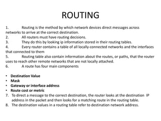
- 1. ROUTING 1. Routing is the method by which network devices direct messages across networks to arrive at the correct destination. 2. All routers must have routing decisions. 3. They do this by looking ip information stored in their routing tables. 4. Every router contains a table of all locally-connected networks and the interfaces that connected to them 5. Routing table also contain information about the routes, or paths, that the router uses to reach other remote networks that are not locally attached. 6. A route has four main components • Destination Value • Mask • Gateway or interface address • Route cost or metric 7. To direct a message to the correct destination, the router looks at the destination IP address in the packet and then looks for a matching route in the routing table. 8. The destination values in a routing table refer to destination network address.
- 2. FUNCTION OF ROUTERS 1. A router is networking device that connects a local network to other local networks. 2. The routers reads the network portion of the destination IP address and uses it to find which one of the attached networks is the best way to forward the message to the destination. 3. Routers encode and also decode the packet that is encapsulated within the frame. 4. Each port or interface on a router connects to a different local network. 5. Every router contains a table of all locally-connected networks and the interfaces that connect to them. These routing tables can also contain information about the routers, or paths, that the router uses to reach other remote networks that are not locally attached 6. Router maintains two tables i.e ARP and ROUTING table.
- 3. Routing types:- MANUALLY:-Remote networks are manually entered into the route table using static routes. DYNAMICALLY:-remote routes are automatically learned using dynamic routing protocol.
- 4. Anatomy of a Router A Router is a Computer
- 5. Anatomy of a Router Router CPU and OS
- 6. Anatomy of a Router Router Memory Memory Volatile / Non-Volatile Stores RAM Volatile • Running IOS • Running configuration file • IP routing and ARP tables • Packet buffer ROM Non-Volatile • Bootup instructions • Basic diagnostic software • Limited IOS NVRAM Non-Volatile • Startup configuration file Flash Non-Volatile • IOS • Other system files
- 7. Anatomy of a Router Inside a Router 1. Power Supply 2. Shield for WIC 3. Fan 4. SDRAM 5. NVRAM 6. CPU 7. Advanced Integration Module (AIM) 1 2 2 6 5 3 4 7
- 8. Anatomy of a Router Router Backplane Two 4 GB Flash Card Slots Double-Wide EHWIC slots EHWIC 0 AUX Port LAN Interfaces USB Ports Console USB Type B Console RJ45
- 9. Anatomy of a Router Connecting to a Router WAN Interface AUX Port LAN Interfaces Console USB Type B Console RJ45
- 10. Anatomy of a Router LAN and WAN Interfaces Serial Interfaces LAN Interfaces
- 11. Router Boot-up Cisco IOS The Cisco IOS operational details vary on different internetworking devices, depending on the device’s purpose and feature set. However, Cisco IOS for routers provides the following: • Addressing • Interfaces • Routing • Security • QoS (Quality of service) • Resources Management
- 13. Router Boot-up Router Bootup Process
- 14. INTRODUCTION OF CISCO PACKET TRACER
- 15. Software uses for initial setup • PuTTY • Secure CRT • Tera Term • Hyper Terminal • OSX Terminal COMMAND LINE INTERFACE Programs - Accessories - Communication - HyperTerminal Connect to window - select com1 - ok
- 16. IOS Modes 1.User EXEC Mode: – router> - ping,show,enable,etc 2. Privileged EXEC Mode: – router#- debug,reload,configure etc. 3.Gobal Configuration Mode:-router(config)# Hostname,enable secret,ip route,interface etc. 4. Specific Configuration mode:-router(config-if)# Configuration changes to specific part of the router like lines and interfaces. 5. . ROMMON Mode:-rommon1> From ROM monitor mode, you can boot the device or perform diagnostic tests.
- 17. Basic show commands:- router# show version router# show flash router# show interface Router# show version Cisco IOS Software, C1900 Software (C1900-UNIVERSALK9-M), Version 15.2(4)M1, RELEASE SOFTWARE (fc1) Technical Support: http://www.cisco.com/techsupport Copyright (c) 1986-2012 by Cisco Systems, Inc. Compiled Thu 26-Jul-12 19:34 by prod_rel_team ROM: System Bootstrap, Version 15.0(1r)M15, RELEASE SOFTWARE (fc1) Router uptime is 10 hours, 9 minutes System returned to ROM by power-on System image file is "flash0:c1900-universalk9-mz.SPA.152-4.M1.bin" Last reload type: Normal Reload Last reload reason: power-on <Output omitted> Cisco CISCO1941/K9 (revision 1.0) with 446464K/77824K bytes of memory. Processor board ID FTX1636848Z 2 Gigabit Ethernet interfaces 2 Serial(sync/async) interfaces 1 terminal line DRAM configuration is 64 bits wide with parity disabled. 255K bytes of non-volatile configuration memory. 250880K bytes of ATA System CompactFlash 0 (Read/Write) <Output omitted> Technology Package License Information for Module:'c1900' ----------------------------------------------------------------- Technology Technology-package Technology-package Current Type Next reboot ------------------------------------------------------------------ ipbase ipbasek9 Permanent ipbasek9 security None None None data None None None Configuration register is 0x2142 (will be 0x2102 at next reload)
- 18. Configuring a Cisco Router router> * User Mode/User Executable Mode. router> enable (enter) Router# *Privileged Mode/Enable Mode-Executable Mode. Router# configure terminal (enter) Router(config)# *Global Configuration Mode Router(config)#interface fastethernet 0/ s0 / s1 (enter) Router(config-if)# *Specific Configuration mode
- 19. Router(config)# line console 0 (enter) Router(config-line)#password xxxxxx Router(config-line)# login Router(config)#username xxxxx password xxxxx Router(config)# line console 0 Router(config-line)#login local Router(config)#enable password xxxxx Router(config)#enable secret xxxxxx Router(config)#line vty 0 4 Router(config-line)#password xxxxx Router(config)# login Router(config)#service password-encryption Router(config)# hostname HOR(enter) HOR(config)# SETTING USER MODE PASSWORD TO SET PASSWORD FOR THE PRIVILEGED MODE SETTING PASSWORD FOR REMOTE LOGIN TO ENCRYPT ALL THE PASSWORDS TO CHANGE HOST NAME TO SET USERNAME & PASSWORD FOR THE USER MODE
- 20. Show commands Router# show running-config Router# show startup-config Router# show ip interface brief Router# show ip route Router# show protocols ETC… Commands copying from RAM TO NVRAM Router # copy running config startup config
- 21. Configure Initial Settings Router Configuration Steps Router> enable Router# configure terminal Enter configuration commands, one per line. End with CNTL/Z. Router(config)# hostname R1 R1(config)# 192.168.10.0/24 R2 192.168.11.0/24 10.1.1.0/24 10.1.2.0/24 209.165.200.224 /30 .226 .10 .10 .10 .10 .1 .1.1 G0/1 .225 S0/0/0 G0/0 .1 R1 PC1 PC2 Router> en Router# conf t Enter configuration commands, one per line. End with CNTL/Z. Router(config)# ho R1 R2(config)# OR R1(config)# enable secret class R1(config)# R1(config)# line console 0 R1(config-line)# password cisco R1(config-line)# login R1(config-line)# exit R1(config)# R1(config)# line vty 0 4 R1(config-line)# password cisco R1(config-line)# login R1(config-line)# exit R1(config)# R1(config)# service password-encryption R1(config)# R1(config)# banner motd # Enter TEXT message. End with the character '#'. *********************************************** WARNING: Unauthorized access is prohibited! *********************************************** # R1(config)# R1# copy running-config startup-config Destination filename [startup-config]? Building configuration... [OK] R1#
- 22. Configure Interfaces Configure LAN Interfaces 192.168.10.0/24 R2 192.168.11.0/24 10.1.1.0/24 10.1.2.0/24 209.165.200.224 /30 .226 .10 .10 .10 .10 .1 .1.1 G0/1 .225 S0/0/0 G0/0 .1 R1 PC1 PC2 R1# conf t Enter configuration commands, one per line. End with CNTL/Z. R1(config)# R1(config)# interface gigabitethernet 0/0 R1(config-if)# ip address 192.168.10.1 255.255.255.0 R1(config-if)# description Link to LAN-10 R1(config-if)# no shutdown %LINK-5-CHANGED: Interface GigabitEthernet0/0, changed state to up %LINEPROTO-5-UPDOWN: Line protocol on Interface GigabitEthernet0/0, changed state to up R1(config-if)# exit R1(config)# R1(config)# int g0/1 R1(config-if)# ip add 192.168.11.1 255.255.255.0 R1(config-if)# des Link to LAN-11 R1(config-if)# no shut %LINK-5-CHANGED: Interface GigabitEthernet0/1, changed state to up %LINEPROTO-5-UPDOWN: Line protocol on Interface GigabitEthernet0/1, changed state to up R1(config-if)# exit R1(config)#
- 23. Configure Interfaces Verify Interface Configuration 192.168.10.0/24 R2 192.168.11.0/24 10.1.1.0/24 10.1.2.0/24 209.165.200.224 /30 .226 .10 .10 .10 .10 .1 .1.1 G0/1 .225 S0/0/0 G0/0 .1 R1 PC1 PC2 R1# show ip interface brief Interface IP-Address OK? Method Status Protocol GigabitEthernet0/0 192.168.10.1 YES manual up up GigabitEthernet0/1 192.168.11.1 YES manual up up Serial0/0/0 209.165.200.225 YES manual up up Serial0/0/1 unassigned YES NVRAM administratively down down Vlan1 unassigned YES NVRAM administratively down down R1# R1# ping 209.165.200.226 Type escape sequence to abort. Sending 5, 100-byte ICMP Echos to 209.165.200.226, timeout is 2 seconds: !!!!! Success rate is 100 percent (5/5), round-trip min/avg/max = 1/2/9 ms R1#
- 24. Configuring the Default Gateway Default Gateway on a Host 192.168.10.0/24 192.168.11.0/24 G0/1 .1 .1 G0/0 R1 .10 PC1 .10 PC2 .10 PC4 .10 PC3 192.168.10.0/24 192.168.11.0/24 G0/1 .1 .1 G0/0 R1 .10 PC1 .11 PC2 .11 PC4 .10 PC3 Default Gateway not needed Default Gateway needed
- 25. Configuring the Default Gateway Default Gateway on a Switch
- 26. In static routing , we are manually adding the destination network to our routing table. There are four types of IPv4 and IPv6 static routes. STANDARD STATIC ROUTE DEFAULT STATIC ROUTE SUMMARY STATIC ROUTE FLOATING STATIC ROUTE Router (config)# ip route <destination N/w> <DSNM> <exit interface> Example :- Router (config)# ip route 30.0.0.0 255.0.0.0 20.0.0.2 (standard static route) Router (config)# ip route 0.0.0.0 0.0.0.0 172.16.2.2 (default static route)
- 27. DYNAMIC ROUTING There are two types of dynamic routing protocol are used for routing: 1. DISTANCE VECTOR PROTOCOL (RIP,IGRP,EIGRP) Identifies how far it is to the destination network and is based on a metric such as the hop count,cost,bandwidth,delay. 2. LINK STATE PROTOCOL (OSPF,IS-IS) Specifies the direction of the next-hop router or exit interface to reach the destination. 3. BORDER GATEWAY PROTOCOL (BGP) Path vector routing protocol.
- 28. RIP (ROUTING INFORMATION PROTOCOL) 1. To enable RIP routing for a network,use the network network-address router configuration mode command. 2. Advertises the specified network in RIP routing updates sent to their routers every 30 seconds.hold down time 180 secs,flushed after 240 secs. 3. Choose best path based on hop count ( max hop count -15). RIP V1 RIP V2 Support VLSM NO YES Support CIDR NO YES Support Summarization NO YES Support Authentication NO YES Updates forward to Address 255.255.255.255 224.0.0.9 Maximum hop count 15 15
- 29. ROUTER 1 R1(config)# router RIP R1(config-router)# version 2 R1(config-router)# network 192.168.1.0 R1(config-router)# network 192.168.3.0 R1(config-router)# no auto-summary ROUTER 2 R1(config)# router RIP R1(config-router)# version 2 R1(config-router)# network 192.168.2.0 R1(config-router)# network 192.168.3.0 R1(config-router)# no auto-summary 192.168.3.0 192.168.1.0 192.168.2.0
- 30. EIGRP(Enhanced Gateway Routing Protocol) It is an advanced distance vector routing protocol developed by cisco systems. 1. Supports to classless Address 2. Resources uses medium. 3. Scalability large 4. Speed high Types of EIGRP Packets:- Hello Packets :- To discover routers Updates Packets :- Convey routing information. Acknowledge Packets :-Acknowledge the receipt of packets. Query Packets :- Used to query routes from neighbors. Reply Packets:- send in response to an EIGRP query. Command for EIGRP :- Router(config)# router eigrp autonomous-system The autonomous-system between the number 1 and 65,535. All routers within the EIGRP routing domain must use the same autonomous system number.
- 31. R1(config)#router eigrp 100 R1(config-router)# network 192.168.0.0 R1(config-router)# network 57.35.169.0
- 32. OSPF(Open Shortest Path First) OSPF features includes:- Classless:- It is classless by design, therefore it supports VLSM and CIDR. Efficient :- it uses the SPF algorithm to choose the best path. Fast Convergence :- It quickly propagates network changes. Scalable :- It works well in small and large network sizes. Routers can be grouped into areas to support a hierarchical system. Secure :- OSPF routers only accept encrypted routing updates from the peers with the same pre-shared password. OSPF creates and maintain three databases :- Adjacent databases – Create the neighbour table. Link-state database (LSDB)-Create the topology table. Forwarding database:- Create the routing table.
- 33. Routing Protocol Messages :- OSPF exchanges messages to convey routing information using five types of packets. Hello packets Database description packet Link-state request packet Link-state update packet Link-state acknowledge packet An OSPF area is a group of routers that share the same link-state information in their LSDBs. Single-Area OSPF – all routers are in one area called the backbone area (area 0) Multiarea OSPF – OSPF is implemented using multiple areas, in a hierarchal fashion. All areas must connect to the backbone area ( area 0).Routers interconnecting the area referred to as Area Border Routers (ABR).
- 34. ROUTE SOURCE ADMINISTRATIVE DISTANCE Connected 0 Static 1 EIGRP Summary route 5 External BGP 20 Internal EIGRP 90 IGRP 100 OSPF 110 IS-IS 115 External EIGRP 170 Internal BGP 200
- 36. 1. Improved Security 2. Reduced cost 3. Better performance 4. Smaller broadcast domain 5. IT efficiency 6. Management efficiency S1#show vlan brief Default vlan is 1 1. All ports assigned to vlan to fwd data by default 2. NATIVE VLAN – native vlan is vlan 1 by default 3. Management vlan is vlan 1 by default 4. Vlan1 cannot be renamed or deleted. PORT MODE 1. Access mode (default) 2. Trunk mode
- 37. 10.0.0.2 20.0.0.2 Ip-20.0.0.1 255.0.0.0 Default gateway-20.0.0.100 255.0.0.0 Ip-10.0.0.1 255.0.0.0 Default gateway-10.0.0.100 255.0.0.0 Router on stick
- 38. S1(config)# vlan 10 S1(config-vlan)# name paybranch S1(config)# interface fa0/1 S1(config-if)# switchport access vlan 10 S1(config)# vlan 20 S1(config-vlan)# name srbranch S1(config)# interface fa0/11 S1(config-if)# switchport access vlan 20 S1(config)# interface range fa0/2-10 S1(config-if)# switchport access vlan 10 S1(config)# interface range fa0/12-20 S1(config-if)# switchport access vlan 20
- 39. S1(config)# interface fa0/24 S1(config-if)# switchport mode trunk S1(config-if)#end Router on Stick Router(config)#int fa0/0 Router(config-if)#no shutdown Router(config)#interface fa0/0.10 Router(config-subif)#encapsulation dot1q 10 Router(config-subif)#ip address 10.0.0.100 255.0.0.0 Router(config)#interface fa0/0.20 Router(config-subif)#encapsulation dot1q 20 Router(config-subif)#ip address 20.0.0.100 255.0.0.0
- 40. Configuring Port Security on an Interface To restrict traffic through a port by limiting and identifying MAC addresses of the stations allowed to access the port, perform this task: Command Purpose Step 1 Switch(config)# interface interface_id Enters interface configuration mode and enters the physical interface to configure, for example gigabitethernet 3/1. Step 2 Switch(config-if)# switchport mode access Sets the interface mode as access; an interface in the default mode (dynamic desirable) cannot be configured as a secure port. Step 3 Switch(config-if)# switchport port- security Enables port security on the interface. Step 4 Switch(config-if)# switchport port- security maximum value (Optional) Sets the maximum number of secure MAC addresses for the interface. The range is 1 to 3072; the default is 1.
- 41. Step 5 Switch(config-if)# switchport port- security violation {restrict | shutdown} (Optional) Sets the violation mode, the action to be taken when a security violation is detected, as one of these: •restrict—A port security violation restricts data and causes the Security Violation counter to increment and send an SNMP trap notification. •shutdown—The interface is error-disabled when a security violation occurs. Note When a secure port is in the error-disabled state, you can bring it out of this state by entering the errdisable recovery cause psecure- violation global configuration command or you can manually reenable it by entering the shutdown and no shut down interface configuration commands. Step 6 Switch(config-if)# switchport port- security limit rate invalid-source-mac Sets the rate limit for bad packets.
- 42. Step 7 Switch(config-if)# switchport port- security mac- address mac_address (Optional) Enters a secure MAC address for the interface. You can use this command to enter the maximum number of secure MAC addresses. If you configure fewer secure MAC addresses than the maximum, the remaining MAC addresses are dynamically learned. Step 8 Switch(config-if)# switchport port- security mac- address sticky (Optional) Enable sticky learning on the interface. Step 9 Switch(config-if)# end Returns to privileged EXEC mode. Step 10 Switch# show port-security address interface interface_id Switch# show port-security address Verifies your entries.