
Recomendados
Más contenido relacionado
La actualidad más candente
La actualidad más candente (20)
Destacado
Destacado (20)
Similar a 132 KV GSS CHAMBAL JAIPUR
Similar a 132 KV GSS CHAMBAL JAIPUR (20)
Último
Último (20)
132 KV GSS CHAMBAL JAIPUR
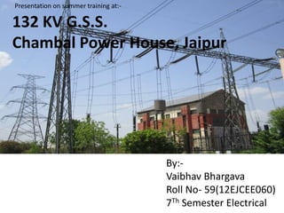
- 1. By:- Vaibhav Bhargava Roll No- 59(12EJCEE060) 7Th Semester Electrical 132 KV G.S.S. Chambal Power House, Jaipur Presentation on summer training at:-
- 2. Introduction About R.R.V.P.N.L • It was established on 19 July, 2000 by Govt. of Rajasthan under the provisions of the Rajasthan Power Sector Reforms Act, 1999 as the successor company of RSEB. • Its aim is to provide reliable electric transmission service to customers. • It is responsible for installing of EHV Lines and GSS of 765 KV, 400 KV, 220 KV, 132 KV rating including their maintenance.
- 3. RVPN System at Glance
- 4. Contents • Introduction about GSS Chambal • Site Selection Criteria • Equipments Used in Yard • Single Line Diagram • Control Room • Transformer • Lightning Arrester(LA) • Capacitive Voltage Transformer(CVT) • Isolator • Circuit Breaker(CB) • Current Transformer(CT) • Relays • Earthing • Battery Room • Power Line Carrier Communication(PLCC) • Conclusion
- 5. Introduction About 132KV GSS Chambal • It is located at Hawa Sadak, Jaipur Rajasthan • It was commissioned in the year 1962 as a part of Chambal Project. • In this hydro generation was proposed by RPS,JS,KB. • Initial capacity was 50 MVA.
- 6. Incoming Feeders of 132 KV •Heerapura •Mansarovar-Sanganer(MNSR) •Nallah Power House There are 11 33 KV and 18 11 KV outgoing feeders . Some of them are:- •Durgapura •Vidhan Sabha •22 Godam •Lal Kothi •MREC
- 7. Site Selection Criteria for GSS • Land: choose areas that minimize the need for earth movement and soil disposal. • Water: avoid interference with the natural drainage network. • Vegetation: choose low productivity farming areas or uncultivated land. • Topography: flat but not prone to flood or water stagnation. • Soil: suitable for construction of roads and foundations; low soil resistivity is desirable.
- 8. Equipments in the Yard • TRANSFORMERS • CAPACITIVE VOLTAGE TRANSFORMER • WAVE TRAP • COUPLING CAPACITOR • CAPACITOR BANK • BUS BAR • INSULATORS • ISOLATOR • LIGHTNING ARRESTER • CIRCUIT BREAKER • CURRENT TRANSFORMER • BUS COUPLER
- 9. SYMBOL USED IN SLD
- 10. Single Line Diagram • A Single Line Diagram (SLD) of an Electrical System is the Line Diagram of the concerned Electrical System which includes all the required Electrical Equipment connection sequence wise from the point of entrance of Power up to the end of the scope of the mentioned Work.
- 12. Noticeable aspects of S.L.D. • Naming of components • Sequence of equipments for an incoming or an outgoing feeder • 11KV & 33KV Feeders • Symbol Chart
- 13. Sequence Of Equipments for an incoming or an outgoing feeder L. A. P.T. / C.V.T C. T. C. B. LIGHTNING ARRESTER POTENTIAL X-MER/CVT ISOLATOR CURRENT TRANSFORMER CIRCUIT BREAKER ISOLATOR BUS BAR
- 14. CONTROL ROOM The diagram made on the control panel is known as mimic diagram. Colors of signals are synchronized as follows: Red – For circuit breaker or isolator switch is in closed position. Green - For circuit breaker is in open condition. Amber – Indicates spring is charged.
- 15. TRANSFORMER
- 16. Main parts of Transformer • MAIN TANK • CONSERVATOR TANK • BUSHINGS • BREATHER • RADIATORS • DRAFT FANS • BUCHHOLZ RELAY • TEMPERATURE INDICATORS • TAP CHANGER
- 17. S.NO. MAKE VOLTAGE CAPACITY CURRENT(ON HV SIDE) 1 T&R 132/33 KV 40/50 MVA 179.95/218.5 2 T&R 132/33KV 40/50 MVA 179.95/218.5 3 CROMPTON 132/11 KV 16/20 MVA 69/87.5 4 ALSTOM 132/11KV 10/12.5 MVA 69/87.5 5 T&R 132/11 KV 16/20 MVA 69/87.5 6 T&R 132/11 KV 16/20 MVA 69/87.5 Specifications
- 18. Types of Protection Relays of Transformer Primary protection • Differential Protection • Neutral displacement relay Secondary / backup protection • Over current relay • Earth fault relay Auxiliary protection • Buchholz relay • Oil surge relay • Winding temperature relay • Oil temperature relay • Pressure Release Device(PRD)
- 19. TRANSFORMER OIL FILTRATION UNIT
- 20. S. No. Voltage(KV) Name of Conductor 1 400v ACSR Weasel 2 11 KV Weasel 3 33 KV Dog 4 132 KV Panther 5 220 KV Zebra 6 400 KV Moose 7 765 KV Tarantula Types of Conductor •The size and coupling type of conductor is decided by its voltage level.
- 21. Lightning Arrester •It is a protective device that reduces excessive voltage resulting from lightning to a safe level by grounding the discharge. •It shows dual characteristics. •During Lightning it works as super conductor whereas normally it works as insulator.
- 22. CVT •CVT in a substation is used for measurement, protection and as coupling device in PLCC. •In its basic form the device consists of three parts: two capacitors across which the transmission line signal is split, an inductive element to tune the device to line frequency, and a transformer to isolate and further step down the voltage for instrumentation or protective relay.
- 23. Isolator • An Isolator is a manually operated mechanical switch which separates a part of the electrical power system normally at off load condition. • While opening the circuit, circuit breaker opens first and then isolator & while closing the circuit the isolator closed first and then circuit Breaker.
- 24. CIRCUIT BREAKER
- 25. Circuit Breaker Comparison SF6 CIRCUIT BREAKER • Gas is used as an arc quenching medium. • It is an electronegative gas. • It has a tendency to absorb free electrons. VACUUM CIRCUIT BREAKER • Vacuum is used as an arc quenching medium. • It has very fast rate of recovery of dielectric strength. • The arc is extinguished quickly.
- 26. Current Transformer •Current transformer are commonly used for protection and measuring of high values of currents. • C.T. is used for reducing A.C. from higher to low value for measurement/protection/control. •The primary winding of a current transformer is connected in series with the circuit whose current to be sensed and across the secondary of current transformer, the operating coil of the relay is connected.
- 27. Relays • It is an electrically operated switch. • Major types of Relay are Electromagnetic & Static type. • It controls High Voltage Electrical Circuits with low voltage signal • In GSS control panels consisting of Relay operates at 110 V DC.
- 28. Important Relays Used at GSS • Over current Relay • Earth Fault Relay • Differential Protection • Distance Protection
- 29. RELAY WORKING
- 30. Earthing •It provides a surface under the substation which has uniform potential nearly equal to zero or Absolute Earth Potential. • It is of two types oNeutral Earthing oEquipment Body Earthing
- 31. Battery Room & Charger •Battery Bank forms the heart of GSS •It is responsible of supplying all the relay panels which are situated in control room •Typically room containing the battery bank is dark in color to avoid the evaporation of solution inside the battery
- 32. Wave Trap •Wave trap is used for power line carrier communication purpose as a Low pass filter which allow power frequency signal to pass and high frequency signals are blocked. • It is connected to the main incoming feeder so that it can trap the waves which may be dangerous to the instruments present in the substation.
- 33. PLCC • Protection signaling, speech and data transmission for system operation and control, management information systems etc. are the main needs which are met by PLCC. • High frequency signals in the range of 50 KHZ to 400 KHZ commonly known as the carrier signal and to result it with the protected section of line suitable coupling apparatus and line traps are employed at both ends of the protected section • The main application of power line carrier has been from the purpose of supervisory control telephone communication, tele- metering and relaying.
- 34. Conclusion • The training at grid substation has improved my understanding of the subject electrical power transmission and distribution. During the training period, I came to know that, there is a much difference between theoretical understanding and practical approach to the subject. • If we see the transformer it is shown in textbooks two windings changing the voltage level which seems very easy concept. • But practically it is a huge machine with a no. of parts and fittings, protection devices each of which is designed with a very specific purpose. • But of course to design new technology, theoretical knowledge has its own importance but without practical touch, it is of no use.