This document describes the design and fabrication of a multipurpose machine for sugarcane planting. Sugarcane planting is currently a labor-intensive process done manually. The authors developed a new machine that can automatically cut sugarcane, feed the pieces into furrows, and apply fertilizer and pesticides. The machine uses a cam-operated mechanism with a rotary cutter to cut sugarcane into uniform lengths which are then fed into furrows by gravity. This ensures uniform density of sugarcane planting. The machine was designed with wheels, shafts, sprockets, and other components to enable it to function across different sizes of land with only 2-3 laborers. This reduces labor costs and speeds up
2. Vaibhav V. Randive et al. Design and Fabrication of Multipurpose Machine for Sugarcane Planting
304| MIT College of Engineering, Pune, India, AMET 2016, INPRESSCO IJCET Special Issue-4 (March 2016)
1.3 Furrow dimension
We are using the ridge and furrow method which is
most common method of sugarcane planting followed
in Maharashtra. Below diagram shows the dimensions
of furrow. Distance between two furrows and depth of
furrow are the important dimensions.
Fig.1 Furrows dimension
Length between two furrows- 90 cm
Height of the furrow- 50 cm
1.4 Length and spacing of sugarcane
Pieces of the sugarcane are planted with some distance
between the two pieces. Length of the sugarcane pieces
are selected such that there two eyes on the pieces
which gives maximum output as compared with the
one eye and three eye methods. It avoids heavy risk of
gaps in single eye bud and over population by three
eye bud planting method.
Fig.2 planting dimension
Length of sugarcane piece- 30 cm
Distance between two pieces- 10 cm
2. Design Section
2.1 Distance between two wheels (Length of the wheel
axle)
For smooth running of the machine the wheels of the
machine should travel through the furrow otherwise
machine will tilt in one side. Since the distance
between two furrows is 90cm so we kept the distance
of 90cm between two wheels.
Distance between two wheels- 90 CM
2.2 Diameter of the wheel
During deciding the height of the axle from ground
surface the depth of the furrow is important factor. To
avoid the destruction of the furrow due to axle the
height of the axle should be greater than the depth of
furrow. Generally the height of the furrow varies in the
30-50cm as per the type of soil.
Diameter of wheel – 80CM
2.3 Axle
Considering the weight of the person and sugarcane,
total weight on the shaft is 200kg approximately.
Number of shaft-2
Weight on one shaft -100kg =1KN (approx.)
Maximum bending moment = 50000 N-mm
Torsional moment = 26720837 N-mm
Material of shaft=30c8
Yield strength =400N/mm2 fos - 2
Allowable shear stress= τmax = 100 N/mm2
Using Shear Stress Theory
τmax = 16/(π*d3) * (Mb + Mt)0.5
Diameter of the shaft – 52 mm
2.4 Speed calculations
For linear speed of 2 km/hr. of tractor
Linear speed of wheel (v) = 0.56 m/sec
Rpm of the wheel = 13.33
For 1 revolution of the wheel length of sugarcane
required for feeding = 1884.95 mm
Piece length of sugarcane = 300mm
Number of pieces cut for 1 revolution = 1884.95 /300
= 6.28 = 7
Chain Drive
Power = 5hp = 3730watt
Maximum speed =200rpm (approximately)
Power transmitted (P) = 3.73 kW
From standard table of power rating, Chain no. 12B
(KW rating-3.75) is suitable for above application.
The dimensions of the chain as follows:
Pitch (p) = 19.05 mm Width (b) = 11.68 mm
Roller Diameter (d1) = 12.07 mm
Transverse pitch (pt) = 19.46 mm
Braking load (N) = 28900 N
To avoid polygonal effect Z2= 11
Pitch circle diameter of driven sprocket =68 mm
Now, N2/N1 = 46.65/13.33 = 3.5 Number of teeth
on driving sprockets=Z1 = 3.5*11 = 39
Pitch circle diameter of driving sprocket = 240 mm
Center distance between the sprocket (a) = 650 mm
Number of chain links = 94
Springs
Assuming force of 50N 0n the spring during extension
Spring Material= Patented Cold drink Steel Wire
Tensile strength=1190 N/mm
3. Vaibhav V. Randive et al. Design and Fabrication of Multipurpose Machine for Sugarcane Planting
305| MIT College of Engineering, Pune, India, AMET 2016, INPRESSCO IJCET Special Issue-4 (March 2016)
Modulus of rigidity G=81370N/mm2
Permissible stress=0.50 Sut
Max. Spring Force=P=50N
Required Deflection= δ =70mm
Spring Index=C=8 … (std. table)
Wire diameter (d) =2mm
Mean Coil Dia. =D=C*d=2*8=16mm
No. of Active Coil (N) =55
End Type= Square &Ground Ends
N=Nt-2 Nt =57
Solid Length=Nt* d=57*2=114 mm
Total Gap= (Nt-1)*(0.5) = 56*(0.5) = 28mm
Free Length=114+28=142mm
Bearing Design
Shaft diameter=52mm
Load on bearing=1KN (Radial)
Equivalent bearing load =P=X V Fr + Y Fa
P=equivalent bearing load Fr=Radial load
Fa=Axial load V=Race rotation factor
In this application inner race is rotates whole the outer
race is stationery. Therefore V=1
P=1*1000=1000N
Bearing life for automobile application is given as 50
million revolutions. L10=50 million rev.
L10=(C/P)p p=10/3 For roller bearing
Dynamic Load Capacity=3233.3N
From std. table for dynamic load capacity of 3233.63N
& 50mm inner diameter bearing is 61810 (6240N)
Inner diameter=50mm Outer diameter=65mm
Axial width=7mm
1.5 Guide ways
Length of the guide ways=400mm
Width of guide ways=50mm
Thickness of guide ways=20mm
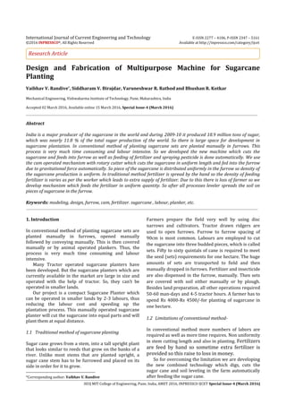
2. Modeling
Fig.3 project structure
Motor is used to rotate the rotary cutter with a speed
of 500rpm whereas the supporting plate with motor
and cutter reciprocates on the guide ways.
Reciprocating motion of cutter and plate is controlled
by the cam and follower. Follower plate follows the
curved shape of the cam. Cam is rotated at particular
by drive train from the main axle of the machine. So
camshaft is depending on the linear movement of the
machine. After cutting the billets drop down in the
furrow. For travel of 40cm of machine there is one
rotation of the camshaft. So, we get one piece of 30cm
for 40cm travel or linear movement.
For one rotation of the cam is there are 3 function are
exist:
1. Cutting: During first 1200 angle of rotation there is
cutting stroke and the cutter moves towards the
sugarcane and cuts the piece .During the cutting there
is extension of the helical spring which connected
between the supporting (motor) plate and frame. The
forward movement of the cutter is 70mm which cuts
the sugarcane completely and piece of sugarcane fall
down in the furrow.
2. Return: After completion of cutting the rotor with
plate moves backwards due to return force of the
extended spring. For fast return stroke we give the less
angle of rotation of cam.
3. Dwell: During this period there is no improvement of
the cutter and plate. The sugarcane comes down for
cutting of next piece. So after completion of this period
again cycle is repeated.
Conclusion
1) From the simulation of the entire mechanism we
got result as the safest design which can be able to
take maximum load without failure with the given
factor of safety.
2) And we are having a complete machine with the
proper structural arrangement of the elements.
3) By using this machine we are getting uniformity in
planting with minimum time and in less cost as
compared to conventional method.
4) Also here we are added some additional
accessories to this machine like fertilizer and
pesticides feedings which raises its advantages.
5) We can attach this machine to any driving vehicles
like tractors so furrow making and planting takes
place simultaneously.
6) So, by combining all these attachments and
mechanisms, accessories we are getting an whole
planting process automatically with simultaneous
other works like pesticides sprays etc. and the
most important thing is that, all the activities are
carried out in an accurately controlled manner
which results into the highly précised planting
process.
References
R. R. Price, R. M. Johnson, R. P. Viator, J. Larsen, A.
Peters, Fiber Optic Yield Monitor For A Sugarcane
Harvester, American Society of Agricultural and Biological
Engineers, Vol. 54
4. Vaibhav V. Randive et al. Design and Fabrication of Multipurpose Machine for Sugarcane Planting
306| MIT College of Engineering, Pune, India, AMET 2016, INPRESSCO IJCET Special Issue-4 (March 2016)
H.A. Abd, El Mawla, B. Hemida, W.A. Mahmoud,( 2014), Study
On The Mechanization Of Sugarcane Transplanting,
International Journal of Engineering and Technical
Research, Volume-2,
Umesh S. Patkar, Rajesh W. Lanjewar, (2007), A Tractor
Driven Mechanism For Uniform Planting Of Sugarcane,
13th National Conference on Mechanisms and Machines,
December 12-13,
Holsambre D.G. (1997), Irrigation Management Techniques,
Sugarcane Farming Systems Journal of IWRS, Vol.17 (3) No:
1.pp 1-10.
Dr.R.L.Yadav (2007), Vision-2025, Indian Institute of
Sugarcane Research, Lucknow. 62 p.
C-T. Wu and C.-K. Chen, (2001), Study on Rotating Cutters
with Different Definitions of Helical Angle, The
international journal of advance manufacturing technology,
17:627–638.
Patil, A., A.K.dave and R.N.S. Yaday, (2004), Evaluation of
sugarcane cutter planter, sugar tech, vol.6 (3):121-125.
Dafa’alla,A.M. and M.A.Hummeida, (1991), Performance
evaluation of sugarcane planter, J. King saud. Univ. Agric.
Sci. (1), Vol.3. 5-14