Lathe machine
•
2 recomendaciones•245 vistas

Introduction to Lathe Machine Reference: Elements of Workshop Technology (Vol. 2) Hajra Choudhary and web ref.

Recomendados
Más contenido relacionado
La actualidad más candente
La actualidad más candente (20)
Similar a Lathe machine
Similar a Lathe machine (20)
Más de SBM Polytechnic
Último
Último (20)
Lathe machine
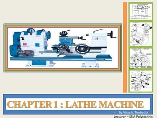
- 1. - By Virag A. Timbadia Lecturer – SBM Polytechnic
- 2. Introduction • Definition: Lathe is a machine, which removes the metal from a work piece to the required shape & size • Principle: A lathe operates on the principle of a rotating work piece and a fixed cutting tool. The cutting tool is feed into the work piece, which rotates about its own Z-axis, causing the work piece to be formed to the desired shape. ViragA.Timbadia 2
- 7. Classification Lathe Machine Speed lathes Engine lathes Bench lathes Capstan and turret lathes Automatic lathes Computer controlled lathes Tracer lathes Tool Room lathes Special Purpose lathes ViragA.Timbadia Wood working Polishing Spinning Belt drive Gear head lathe Missile Lathe Gap Bed Lathe T-Lathe Wheel Lathe Duplicating Lathe 7
- 8. • Speed lathes: High speed lathe with very few ranges of speed and use for wood working, centering polishing and spinning. • Engine lathes: This is similar to the speed lathes but the head stock is little robust in construction. Engine lathes have additional mechanisms to produce a wide range of speeds. • Bench lathes: This is a very small lathe and is generally mounted over a bench. These lathes are small in size and are generally used for doing small and precision works. • Capstan and turret lathes: These are the developments made in engine lathe. These lathes found application in production work. In this lathes the tail stock is replaced by hexagonal turret. Based on the way the turret is mounted they will be classified in to capstan and turret lathes. • Automatic lathes: Every operation is automatically done by employing computers. These lathes have high speed, heavy duty and are used for mass production. These lathes produce jobs with minimum tolerances and of very high accuracy. • Tracer lathes: a lathe that has the ability to follow a template to copy a shape or contour. • Tool Room lathes: it is more accurately built and a wide range of speeds ranging from very low to very high speeds up to 2500rpm can be generated. This is used for doing precision works like tools dies etc. tool room lathes are costlier when compared to engine lathes of same size. ViragA.Timbadia 8
- 9. Specification ViragA.Timbadia 1. The length of bed : It indicates the approximate floor space occupied by the lathe. 2. The length between centers : It is the maximum length of work that can be mounted between the lathe centers. 9
- 10. ViragA.Timbadia BED SWING DIAMETER OVER BED HEIGHT OF CENTRE FROM BED SWING DIAMETER OVER CARRIAGE CARRIAGE Specification 3. The height of centers from the bed : It is the distance between top surface of the bed and the imaginary center line passing through live centre and dead centre. 4. The maximum bar diameter : It is the maximum diameter of work that will pass through the hole of the head stock spindle. 5. The swing diameter of work over bed : It is the largest diameter of work that will revolve without touching the bed. It is twice the height of the centres from the bed. 6. The swing diameter of work over the carriage : It is the largest diameter of work that will revolve over the lathe saddle. It is smaller than the swing diameter over bed. 10
- 12. Components ViragA.Timbadia Lathe Bed & Ways Head Stock Speed Gears Feed Gears Thread Chasing Dial (1/2 Nut) Carriage Cross Slide Compound Tail Stock Coolant System 12
- 13. BED The bed of the lathe provides the foundation for the entire machine and holds various components like headstock, tailstock and carriage in alignment. Components WAY The surfaces of the bed that are finely machined - and upon which the carriage and tailstock slide - are known as "ways". ViragA.Timbadia 13
- 14. Components ViragA.Timbadia HEADSTOCK The headstock of the lathe contains all of the gearing necessary to change • Spindle speed • Carriage feed and • Threading selections. SPEED & FEED GEARS The lathe “speed” and “feed” charts are affixed to the front of the headstock to allow the operator to make the proper feed and speed selections based on the 14
- 17. Magnetic Tool Post ViragA.Timbadia Lead & Feed Screw Single Tool Tool-Post Apron Msm. Components 17
- 20. Lathe Accessories • Divided into two categories – Work-holding, - Supporting, & - Driving Devices • Lathe centers, chucks, faceplates • Mandrels, steady and follower rests • Lathe dogs, drive plates – Cutting-tool-holding devices • Straight and offset tool holders • Threading tool holders, boring bars • Turret-type tool posts ViragA.Timbadia 20
- 21. •Work to be turned between centers must have center hole drilled in each end – Provides bearing surface •Support during cutting •Most common have solid Morse taper shank 60º centers, steel with carbide tips •Care to adjust and lubricate occasionally Lathe Centers ViragA.Timbadia 21
- 22. Removing & Mounting Lathe Centers • Live center – Use knockout bar pushed through headstock spindle (slight tap) • Use cloth over center and hold to prevent damage • Dead center – Turn tailstock hand wheel to draw spindle back into tailstock • End of screw contacts end of dead center, forcing it out of spindle • Remove any burrs from lathe spindle, centers, or spindle sleeves • Clean tapers on lathe centers and in headstock and tailstock spindles • Partially insert cleaned center in lathe spindle – Force center into spindle • Follow same procedure when mounting tailstock center • Check trueness of center – Use dial indicator ViragA.Timbadia 22
- 23. RevolvingTailstockCenters • Replaced solid dead centers for most machining operations • Used to support work held in chuck or when work is being machined between centers • Contains antifriction bearings which allow center to revolve with work piece – No lubrication required between center and work • Types: revolving dead center, long point center, and changeable point center ViragA.Timbadia 23
- 24. MicrosetAdjustableCenter • Fits into tailstock spindle • Provides means of aligning lathe centers or producing slight tapers on work machined between centers • Eccentric slide (dovetail) allows center to be adjusted limited amount to each side of center Self-DrivingLive Center • Mounted in headstock spindle • Used when entire length of work piece is being machined in one operation – Chuck or lathe dog could not be used to drive work • Grooves ground around circumference of lathe center point provide drive • Work usually soft material such as aluminum ViragA.Timbadia 24
- 25. Chucks • Used extensively for holding work for lathe machining operations – Work large or unusual shape • Most commonly used lathe chucks – Three-jaw universal – Four-jaw independent – Collets chuck ViragA.Timbadia 25
- 26. Three-jawUniversalChuck • Holds round and hexagonal work • Grasps work quickly and accurate within few thousandths/inch • Three jaws move simultaneously when adjusted by chuck wrench – Caused by scroll plate into which all three jaws fit • Two sets of jaw: outside chucking and inside chucking ViragA.Timbadia 26
- 27. Four-Jaw Independent Chuck • Used to hold round, square, hexagonal, and irregularly shaped work pieces • Has four jaws – Each can be adjusted independently by chuck wrench • Jaws can be reversed to hold work by inside diameter ViragA.Timbadia 27
- 28. ColletChucks • Most accurate chuck • Used for high-precision work • Spring collets available to hold round, square, or hexagon-shaped work pieces • Each collet has range of only few thousandths of an inch over or under size stamped on collet ViragA.Timbadia 28
- 29. SpringColletChucks • Spring - collet chuck – One form: Hand wheel draws collet into tapered adapter – Another form: Uses chuck wrench to tighten collet on work piece • Can hold larger work than draw-in type | ViragA.Timbadia 29
- 30. JacobsColletChuck • Jacobs collet chuck – Utilizes impact-tightening hand wheel to close collets – Wider range than spring-collet chuck ViragA.Timbadia 30
- 31. MagneticChucks • Used to hold iron or steel parts that are too thin or may be damaged if held in conventional chuck • Fitted to an adapter mounted on headstock spindle • Used only for light cuts and for special grinding applications ViragA.Timbadia 31
- 32. HeadstockSpindleTypes 1. Threaded spindle nose: Screws on in C.W. direction 3. Tapered spindle Nose: Held by lock nut that tightens on chuck 2. Cam-lock spindle nose: Held by tightening cam-locks using T-wrench Chuck aligned by taper on spindle nose ViragA.Timbadia 32
- 33. Faceplates • Used to hold work too large or shaped so it cannot be held in chuck or between centers • Usually equipped with several slots to permit use of bolts to secure work – Angle plate used so axis of work piece may be aligned with lathe centers • Counterbalance fastened to faceplate when work mounted off center – Prevent imbalance and resultant vibrations ViragA.Timbadia 33
- 34. Steady rest • Used to support long work held in chuck or between lathe centers – Prevent springing • Located on and aligned by ways of the lathe • Positioned at any point along lathe bed • Three jaws tipped with plastic, bronze or rollers may be adjusted to support any work diameter with steady rest capacity ViragA.Timbadia 34
- 35. FollowerRest • Mounted on saddle • Travels with carriage to prevent work from springing up and away from cutting tool – Cutting tool generally positioned just ahead of follower rest – Provide smooth bearing surface for two jaws of follower rest ViragA.Timbadia 35
- 36. Mandrel • Holds internally machined work piece between centers so further machining operations are concentric with bore Plain Mandrel Stub Mandrel Gang Mandrel Expanding Mandrel • Several types, but most common are: -Plain Mandrel -Expanding Mandrel -Stub Mandrel -Gang Mandrel ViragA.Timbadia 36
- 37. LatheDogs • Drives work machined between centers • Has opening to receive work and setscrew to fasten the dog to work • Tail of dog fits into slot on drive plate and provides drive to work piece • Made in variety of sizes and types to suit various work pieces Standard bent-tail lathe dog: • Most commonly used for round work pieces • Available with square-head setscrews of headless setscrews • Bent tail engages in slot on drive plate ViragA.Timbadia 37
- 38. Straight-tail lathe dog • Driven by stud in drive plate • Used in precision turning Safety Clamp lathe dog • Used to hold variety of work • Wide range of adjustment Heavy Duty lathe dog • Wider Range than others • Used on all shapes LatheDogs ViragA.Timbadia 38
- 39. Cutting Tool-Holding Devices • Available in three styles – Left-hand offset – Right-hand offset – Straight • Each has square hole to accommodate square tool-bit held in place by setscrew – Angle of approximately 15º to 30º to base of tool-holder ViragA.Timbadia 39
- 40. LH Offset tool holder • Offset to the right • Designed for machining work close to chuck or faceplate and cutting right to left • Designated by letter L RH Offset tool holder • Offset to the left • Designed for machining work close to the tailstock and cutting left to right • Designated by letter R Offset Tool holder ViragA.Timbadia 40
- 41. Toolholder Straight Tool Holder • General-purpose type • Used for taking cuts in either direction and for general machining operations • Designated by letter S Carbide Tool Holder • Has square hole parallel to base of tool holder to accommodate carbide- tipped tool bits • Holds tool bit with little or no back rake • Designated by letter C ViragA.Timbadia 41
- 42. Cutting-Off (Parting)Tools • Used when work must be grooved or parted off • Long, thin cutting-off blade locked securely in tool holder by either cam lock or locking nut • Three types of parting tool holders – Left-hand – Right-hand – Straight ViragA.Timbadia 42
- 43. ThreadingToolholder • Designed to hold special form-relieved thread-cutting tool • Has accurately ground 60º angle – Maintained throughout life of tool – Only top of cutting surface sharpened when becomes dull ViragA.Timbadia 43
- 44. Boring Toolholders • Held in standard tool post – Light boring tool holder • Used for small holes and light cuts – Medium boring tool holder • Suitable for heavier cuts • May be held at 45º or 90º to axis of bar • Mounted on compound rest of lathe – Heavy-duty boring bar holder • Three bars of different diameters • May be held at 45º or 90º to axis of bar ViragA.Timbadia 44
- 45. CompoundRest ToolingSystems • Standard, or round, tool post – Generally supplied with conventional engine lathe – Fits into T-slot of compound rest – Provides means of holding and adjusting type of tool holder or cutting tool required – Concave ring and the wedge or rocker provide for adjustment of cutting- tool height ViragA.Timbadia 45
- 47. Modular(Quick-Change)Tooling • Initially developed for CNC machine tools to improve accuracy, reduce tool-change time and increase productivity – Benefits realized on conventional lathes with systems designed for these machines • Modular tooling system must be rigid, accurate and have quick-change capabilities – Basic clamping unit or turret can hold variety of cutting tool modules • Principal function is to reduce cost of keeping large tool inventory • Tools can be specifically mounted to suit characteristics of work piece • More common systems available – The Super Quick-Change Tool post – The Quadra* Index Tool post – The Super-Six Index Turret – The Vertical Index Turret ViragA.Timbadia 47
- 48. SuperQuick-Change Toolpost • Provides fast, accurate, and reliable method of quickly changing and setting various tool holders for different operations • Locking system has two sliding gibs forced out against tool holder – Handle pulled into lock position – Provides rigid, positive lock with zero backlash ViragA.Timbadia 48
- 49. Quadra*IndexToolpost • Allows four tools to be mounted on turret at same time – Each tool locked independently – Provides flexibility to use from one to four tools simultaneously • Unique indexing system of turret allows it to be set in 24 positions (every 15º) ViragA.Timbadia 49
- 50. Super-SixIndex Turret • Designed to simplify and increase machining productivity on engine lathes when multi-operation jobs require use of more than one tool – Up to six tools for external and internal machining operations – Allows height adjustment for each tool • Tool changes can be made in less than 1 sec ViragA.Timbadia 50
- 51. VerticalIndex Turret(VIT) • Designed to give highest accuracy, fastest tool change and greatest rigidity of any tool system available for engine lathes • Same concept as indexing turrets on CNC lathes – Can hold up to six or eight tools – Closest to performance of CNC lathes ViragA.Timbadia 51
- 52. Alignment Test Lathe Centers • When lathe center aligned Parallel diameters produced • Three common methods used to align – Aligning tailstock – Trial Cut – Test Bar and Indicator Leveling of the Machine True Running of Work Piece ViragA.Timbadia 52
- 53. • Aligning centerlines on back of tailstock with each other • Only a visual check and not too accurate 1. Loosen tailstock clamp nut or level 2. Loosen one of the adjusting screws, depending on direction tailstock must be moved and tighten other until line on top aligns with line on bottom half 3. Tighten screw to lock both halves in place 4. Make sure tailstock lines still aligned 5. Lock tailstock clamp nut or lever Aligning TailStock ViragA.Timbadia 53
- 54. 8. If both diameters not same size, adjust tailstock either toward or away from cutting tool ½ difference of two readings 9. Take another light cut at both points at same cross feed graduated collar setting 10.Measure diameters and repeat. Trial-CutMethod • Small cut taken from each end of work • Diameters measured with a micrometer 1. Take a light cut (.005-.010 in.) to true diameter from section at tailstock end about .250 in. long 2. Stop feed and note reading on graduated collar of cross feed handle 3. Move cutting tool away from work with cross feed handle 4. Bring cutting tool close to headstock end 5. Return cutting tool to same graduated collar setting as at first cut 6. Cut a .500-in (13 mm) length at headstock end and stop lathe 7. Measure both diameters with micrometer ViragA.Timbadia 54
- 55. Test bar anddial indicator 1.Clean lathe and work center, mount test bar 2.Adjust test bar snugly between centers and tighten tailstock spindle clamp 3.Mount dial indicator on tool post or lathe carriage : Indicator plunger should be parallel to lathe bed and contact point set on center 4.Adjust cross-slide : Indicator registers approximately .025 in at tailstock, indicator bezel to 0 5.Move carriage by hand so indicator registers on diameter at headstock end and note indicator reading 6.If both indicator readings not same, adjust tailstock with adjusting screws until indicator registers same at both ends 7.Tighten adjusting screw & tail stock clamp nut that was loosened 8.Adjust tailstock spindle until test bar snug between lathe centers 9.Recheck indicator readings at both ends and, if necessary, adjust tailstock ViragA.Timbadia 55
- 56. ViragA.Timbadia 56 ThreeImportantElements Rotating Speed It expresses with the number of rotations (rpm) of the chuck of a lathe. When the rotating speed is high, processing speed becomes quick, and a processing surface is finely finished. It is better to set low rotating speed at the first stage. Cutting Depth The cutting depth of the tool affects to the processing speed and the roughness of surface. When the cutting depth is big, the processing speed becomes quick, but the surface temperature becomes high, and it has rough surface. Feed (Sending Speed ) The sending speed of the tool also affects to the processing speed and the roughness of surface. When the sending speed is high, the processing speed becomes quick. When the sending speed is low, the surface is finished beautiful.
- 57. ViragA.Timbadia 57 Mechanisms 1. Cam Slot 2. Guide or Frame 3. Lead Screw 4. Hand Lever 5. Pin 6. Circular Plate 7. Half Nuts HalfNut Mechanism
- 61. ViragA.Timbadia 61 TaperTurning Methods of Taper Turning 1. By a broad nose form tool 2. By setting over the tailstock center 3. By swiveling the compound rest 4. By taper turning attachment 5. By Combining longitudinal and cross feed in a special lathe 1. 3.2. Set Over = L x (D−d) 2L = (D−d) L