1. A two-ray model, which consists of two overlapping waves at the receiver, one direct path and
one reflected wave from the ground so it is called as Two ray model.
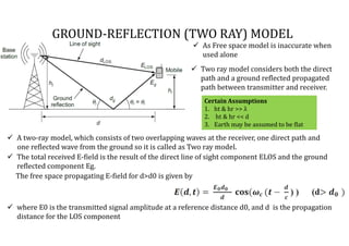
As Free space model is inaccurate when
used alone
GROUND-REFLECTION (TWO RAY) MODEL
The total received E-field is the result of the direct line of sight component ELOS and the ground
reflected component Eg.
The free space propagating E-field for d>d0 is given by
where E0 is the transmitted signal amplitude at a reference distance d0, and d is the propagation
distance for the LOS component
Certain Assumptions
1. ht & hr >> λ
2. ht & hr << d
3. Earth may be assumed to be flat
Two ray model considers both the direct
path and a ground reflected propagated
path between transmitter and receiver.
2. According to the law of reflection in a dielectric,
GROUND-REFLECTION (TWO RAY) MODEL
and
The E-field due to the LOS component at the receiver
can be expressed as
The E-fleld for the ground reflected wave, which has
a propagation distance of d", can be expressed as
We know from the laws of reflection in dielectric,
the value of reflection coefficient Г is (-1)
Total resultant E-field given by
where Γ is the reflection coefficient for ground.
The electric field received by receiver
is can be expressed as
Two propagating waves arrive at the receiver, one LOS wave which travels a distance of d’ and another
ground reflected wave, that travels d”.
By law of reflection in dielectric , = -1
3. Ground-Reflection (Two ray) model
Fig shows the method of images is used to find the path difference LOS & the ground reflected paths.
Both rays travelled from different paths & have different distances so it is must to find path
difference
4. Ground-Reflection (Two ray) model
Using the method of images,
we find the path difference between LOS & the
ground reflected path dg which is denoted as Δ
Assuming now that ht, hr << d, the expression
for Δd can be approximated as
and
Put the value of dLOS & dg in above equation we
get
So, the Path differencd Δ is
5. Ground-Reflection (Two ray) model
2. Phase difference between two E -Field
components denoted as
3. Time delay between the arrival of the two
components easily find using following
relations denoted as
Using Path difference Δ we can find out the value of Phase difference & Time delay
1. Path Difference Δ
6. Ground-Reflection (Two ray) model
By referring phasor diagram the total E field
received by receiver can be expressed as
Fig. shows Phasor diagram of electrical field
components of Line of sight, ground reflected
& total E field received
By using trigonometric identities
By increasing distance d the E tot(d) decays an oscillatory fashion
7. Ground-Reflection (Two ray) model
sin When
= .
=
> ≈
=
=
We can represent the power in terms of E Field as
Power = (
Received power is given by
= (
=
=
As total power radiated is =
=
=
Total received Power
is given by
8. Ground-Reflection (Two ray) model
1. The received power falls off at a rate of 40dB/decade
2.The received power & path loss becomes independent of frequency
The path loss for Two Ray model is expressed as
= 40logd – (10log )
=
Point be noted
1. At small T-R separation distances,
total E-Field is calculated using
equation
2. Where the ground appears in the first
Fresnel zone between Tx & Rx
for = π
d=