First Observation of the Earth’s Permanent FreeOscillation s on Ocean Bottom ...
MGeol Paper
1. The volume of rock eroded from SW South Africa since the start of
the Cretaceous
Adam F. Rawcliffe
School of Earth and Environment,University of Leeds,Leeds,LS2 9JT, UK
INTRODUCTION
Location
The study area is a c. 140,000 km2 region
of southwestern South Africa; spanning
part of the Cape Fold Belt and Karoo
Basin (Fig. 1). It encompasses the entire
Breed, Gouritz and Southern Cape river
systems,plus parts ofthe Olifants, South
Western Cape and Gamtoos river
systems.
Rationale
South Africa has abnormally high
elevation considering it is surrounded by
passive margins; it has an interior
plateau of low relief and high elevation,
separated by the Great Escarpment from
the coastal region of high relief and low
average elevation. By calculating the
volume of sediment removed, this study
aids in the analysis of the long term
landscape evolution. Apatite Fission
Track Analysis (AFTA) data indicates
significant late Cretaceous-Early
Tertiary denudation in the interior of
western south Africa (Gallagher and
Brown, 1999), which is suggested to be
due to uplift associated with the
initiation and growth of the African
superplume (Al-Hajri et al., 2009). The
majority of the sediment eroded from the
study area is thought to have been
transported into the southern offshore
basins (Tinker et al., 2008a), known to
be hydrocarbon reservoirs. Placer
diamond deposits are also known to
exist in the offshore area. This study
provides an estimate of the eroded
sediment volume along with the
composition of the sediment. This will
assist in determining better evaluations
towards reservoir and resource quality,
and the methods used provide an
approach for similar assessments of
comparable source to sink
configurations across the globe; such as
the Norwegian Margin and the Gulf of
Mexico.
Previous Research
There has been little previous research
into the volume of eroded sediment from
South Africa since the start of the
Cretaceous. Tinker et al. (2008b) used
AFTA in three boreholes to estimate 3.3-
4.5 km thickness of stratigraphy eroded
across the southern cape escarpment and
coastal plain since the mid-late
Cretaceous, and up to 7.5 km of
stratigraphy including Early Cretaceous
denudation. This was then compared
with sediment accumulation in the
southern offshore basins (Tinker et al.,
2008a). The offshore accumulated
volume, 268,500 km3, equated to an
onshore vertical elevation of only 860 m
of eroded sediment; an order of
magnitude lower than the 7.5 km
estimated from AFTA. Tinker et al.
(2008a) suggests that; the uncertainty of
using only three boreholes; the removal
of sediment by chemical weathering;
and the ‘loss’ of sediment through
offshore unconformities and sediment-
bypass are the cause of the significant
difference.
Aims
The aim of this study is to build on
previous research and produce an
estimate of a maximum value of the total
volume removed from SW South Africa
since the Cretaceous. Structural cross-
sections establish a maximum elevation
ABSTRACT
The long term landscape evolution of South Africa’s abnormal topography is not
well known. Late Cretaceous-Early Tertiary denudation, due to uplift associated
with the African superplume, is thought to be responsible for the majority of
erosion. A better understanding of the evolution can be determined by
quantifying the maximum volume removed from southern South Africa since the
start of the Cretaceous. The southern offshore basins are of interest to industry,
and with a better understanding of the volume and composition of the eroded
sediment; assessment of reservoir quality can be improved. Several assumptions
have been made to construct structural cross sections across a c.140,000 km2 area
in SW South Africa, with the estimated maximum thickness of lithostratigraphic
groups extrapolated above topography. These have been georeferenced into
3DMove, and a maximum surface fit between. The volume calculated, 1.56 x 10⁶
km3, is compared to previous studies and the implications of this study are
discussed. This study calculates the maximum volume of eroded material;
however it is an order of magnitude greater than the material found in offshore
basins and therefore suggests further research is required.
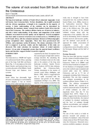
Figure 1. Map show ing the location of the study area in SW South Africa (inset map). The grid
(red lines) show s the locations of the section lines, discussed below , (A; 19°E, 32°05’S –
24°E,32°05’S, B; 19°E,33°05’S - 19°E, 33°05’S, C; 19°E, 33°55’S – 24°E,33°55’S, D; 19°30’E,
32°S – 19°30’E,35°S, E; 20°45’E, 32°S – 20°45’E,35°S, F; 22°15’E, 32°S – 22°15’E,35°S and G;
23°30’E, 32°S – 23°30’E,35°S). Google Earth Image (2014).
2. surface to the stratigraphy prior to
landscape denudation, and a volume
between this and present day topography
can then be calculated.
METHODS
Literature Review
Before the maximum volume of eroded
sediment can be calculated the
stratigraphic configuration prior to
denudation needs to be considered.
Lithostratigraphic groups within the
study area need to be established, along
with their stratigraphic thicknesses
(Table 1). This can then be used to aid
the construction of structural cross-
sections showing the maximum upper
surface of the stratigraphy. The oldest
groups known to have been eroded are
the Table Mountain Group and the
Precambrian Malmesbury Group.
Above these are the Bokkeveld,
Witteberg, Dwyka, Ecca, Beaufort,
Stormberg and Drakensberg Groups.
A bias towards the maximu m
thicknesses in southeastern South Africa
is used to select the preferred
thicknesses, discussed below, of these
groups:
Table Mountain Group; 2,500 m
based on the sum of the individual
formation values suggested by
Shone and Booth (2005) from the
Western Cape region.
Bokkeveld Group; 2,000 m based
on interpretations of map data
within the study area.
Witteberg Group; 2,000 m based on
cross-sections (KING, 2005, KING
et al., 2009) in the Swartberg region.
Dwyka Group; 1,300 m based on
borehole data from the Western and
Central Cape (Rowsell and De
Swardt, 1976).
Ecca Group; 1,800 m based on
values from Sutherland (Adams et
al., 2001) and borehole data
(Rowsell and De Swardt, 1976).
Beaufort Group; 3,000 m based on
values from Sutherland (Adams et
al., 2001).
Stormberg Group; 1,400 m based on
map data within the study area and
values from the Eastern Cape
(Johnson, 1976).
Drakensberg Group; 1,400 m based
on values from the Karoo Foredeep
(Catuneanu et al., 2005).
These values sum to a total of c. 13 km
of sediment above the Table Mountain
Group which is consistent with the 12
km suggested by Johnson (1976), and
the 10 km diagenesis depth of the Table
Mountain Group (Rowsell and De
Swardt, 1976).
Cross Section Construction
Published 1:250,000 geological map
sheets from the Council for Geosciences
span the study area (3218 Clanwillia m,
3220 Sutherland, 3222 Beaufort West,
3319 Worcester, 3320 Ladismith, 3322
Oudtshoorn and 3420 Riversdale).
These provide the initial surface geology
data used to construct basic structural
cross sections, and further constrain
group thicknesses. The calculated
thicknesses (Table 1) of the stratigraphic
groups are used with the Arc method
(Busk, 1929) of cross section
construction (Fig. 2) to assist in the
extrapolation of the seven cross-
sections; three E-W and four N-S, A, B,
C, D, E, F and G respectively (Fig. 1).
Calculations in 3DMove
A mean elevation of present day
topography was calculated using the
'summary statistics’ tool in ArcGIS, the
raster data of the Digital Elevation
Model (DEM). The average elevation
across the study area is 587.4 m, based
on 196187508 data points from the
ASTER (30 m) DEM. This value can be
put into Midland Valley 3DMove
software to create a lower bounding
surface representing the current level of
erosion.
Using 3DMove, the seven structural
cross sections can be georeferenced to
create an interactive 3D version (Fig. 3)
of the grid depicted in Figure 1. The
maximum uppersurface can be digitised
as horizons, with slight modifications
being made to align the upper surface at
cross section intersections. By adding
additional tie-lines between structural
features, faults and folds can be
correlated between cross sections
allowing for a more accurate surface
representation.Using the ‘create surface
from horizon’ tool in 3DMove an upper
surface over the top of the maximu m
horizon lines can be generated to
represent the maximum vertical extent
of sediment prior to erosion. Several
construction methods are available
however the ‘ordinary kriging’ tool
provides the best-fit surface for the
dataset discussed.
Once upper and lower bounding
horizons, maximum vertical extent and
mean present day topography
respectively, have been created; the
‘volume between horizons’ tool in
3DMove can be used to determine the
total volume of eroded sediment. This is
calculated by fitting multiple cubes
between the surfaces. Decreasing the
cube size means a more accurate value
can be determined.
Group Thickness
(m)
Reference
Drakensberg 1,400 (Catuneanu et al.,
2005)
Stormberg 1,400 (Johnson, 1976)
Beaufort 3,000 (Adams et al.,
2001)
Ecca 1,800 (Adams et al.,
2001)
Dwyka 1,300 (Rowsell and De
Swardt, 1976)
Witteberg 2,000 Ros March 03
Bokkeveld 2,000 1:250,000 Map
Data
Table
Mountain
2,500 (Shone and
Booth, 2005)
Table 1. Maximum thicknesses of the
stratigraphic groups, determined through
values from previous studies by various
authors and map data.
Figure 2. Show ing part of crosssection Fbetween 33°Sand 34°S. Cross section constructed from
map sheets and thickness values from Table 1 using the Arc method (Busk, 1929). The top
surface is the maximum extent of the lithologies prior to erosion.
3. ASSUMPTIONS
Several assumptions need to be made in
order to calculate a maximum value of
the total volume removed from SW
South Africa since the Cretaceous.
This study focuses on the total
eroded volume since the start of the
Cretaceous and therefore Cretaceous
and youngeraged deposits have notbeen
included in the total volume. It has been
assumed that these younger deposits,
especially the exposure of Cretaceous
Enon Formation near Oudtshoorn, are
derived from eroded sediment of the pre-
Cretaceous lithostratigraphic groups
being studied; and therefore these can be
ignored and excluded when constructing
cross sections.
There are poor constraints on
the lateral extent of the Stormberg group
and Jurassic aged Drakensberg flood
basalts. Both of these are only exposed
in the Eastern Cape region however
there is no conclusive evidence of a
boundary that would have prevented
these units being laterally extensive
across the Western Cape to the study
area. Dolerite dykes and sills ofJurassic-
age are common across large parts of the
study area that may have fed
Drakensberg flood basalts. As the aim of
this study is to provide a maximum value
of the total volume removed, it is
assumed that these lithostratigraphic
groups have also been eroded.
Due to the large 1:250,000
scale that the study uses, it is not
practical to construct the structuralcross
sections on true scale topography.
Therefore the mean elevation across the
study area was instead used as the
baseline for the cross sections.
Several faults are found across
the study area and the offset along them
has an effect on the extent of the missing
volume. It is assumed that minor faults,
confined within lithostratigraphic
groups, have little effect on the eroded
volume and can be ignored. Large
extensional faults, as at Worcester, are
assumed to be late events that offset all
units, which is demonstrated by
Cretaceous and younger deposits in the
hanging wall.
When using the Arc method
(Busk, 1929) to extrapolate the preferred
lithostratigraphic thicknesses (Table 1),
it was assumed that all units are
conformably overlying one another and
that all have been deformed and folded
at the same time. It is also assumed that
lithostratigraphic thicknesses are
constant across the whole study area.
It is unreasonable to assume the
coastline has remained in its present
location throughout the evolution of the
continent. When extrapolating the
structural cross sections it is assumed
that the lithostratigraphic groups
extended out to sea at a similar elevation
to that at the coast.
If the maximum uppersurfaces
do not intersect after georeferencing the
cross sections into 3DMove; it is first
assumed that construction has strayed
off the section line and therefore slight
rotations to the cross sections align the
top horizons. If this does not align the
horizons it is assumed that it is due to
slight construction errors and horizons
can be edited to intersect using a
maximum bias.
RESULTS
Using the c. 140,000 km study area from
19°E, 32°S – 24°E, 35°S and a value of
c. 13 km of sediment above the Table
Mountain Group; the total volume
removed from SW South Africa since
the Cretaceous is 1.56 x 10⁶ km3. This
equates to an eroded average of 11 km
vertical thickness across the study area.
Figure 4 shows a colour coded overlay
on top of the study area indicating where
the eroded sediment has been removed.
The volumes of eroded sediment are
closely linked with present day features.
The interior Karoo Basin is missing the
least material and is clearly defined by
the cold colours in the north of the study
area. The majority of eroded sediment
has come from the mountainous Cape
Fold Belt (Fig. 4). A small depression in
eroded volume is seen within the Cape
Fold Belt to the west of the study area.
This is the large extensional Worcester
fault and it can be seen to have prevented
erosion of the lithostratigraphic units.
DISCUSSION
Tinker et al. (2008a, b) studied a similar
area along southern South Africa. The
maximum vertical thickness value of
7.5km over the 140,000 km2 area
(Tinker et al., 2008b), equates to a total
eroded volume of 1.05 x 10⁶ km3. The
area examined in this study suggests an
additional 3.5 km eroded vertical
thickness, equating to a total of 1.56 x
106 km3 of eroded sediment. The value
of Tinker et al. (2008a, b) is based on
AFTA of only three boreholes across
southern South Arica and is therefore a
basic estimate, with little constraints.
The value obtained from this study
provides a maximum volume estimate.
Similar causes to those suggested by
Tinker et al. (2008a) likely explain the
order of magnitude difference between
the onshore volume of this study,and the
calculated offshore value of 268,500
km3 (Tinker et al., 2008a); however a
large factor may be due to the poor
knowledge of active drainage basins and
the locations of their sinks over the
period of erosion.
Refinements can be made to this
estimate, and further constraints can be
added to reduce the approximated total
maximum volume of eroded sediment;
discussed below.
Figure 3. Cross section grid fromFigure 1 seen in 3D, after being georeferenced in 3DMove. The
maximum extent of the stratigraphyhas been digitised as a horizon; readyto project the maximum
upper surface betw een cross sections.
4. To improve this estimate; more
structural cross sections, with closer
spacing,are needed to improve the upper
surface. This will allow better
correlation between features and prevent
3DMove from ‘bulk’ interpolation; as
seen in the southern central grid square
between section lines E and F in Figure
4.
There are certain assumptions used in
this study,discussed above,that may be
incorrect and leading to an
overestimation. These are;
The Witteberg group pinches
out in the Clanwilliam region; in this
study it is assumed to be laterally
extensive, however this is therefore an
over estimate. It is possible that other
lithostratigraphic groups are not laterally
extensive, such as the Drakensberg, and
this needs to be taken into account to
better constrain the total maximu m
volume of eroded sediment. By
examining the clast composition of
outcrops of the Cretaceous Enon
formation, as exposed at Oudtshoorn, it
may be possible to determine the lateral
extent of the lithostratigraphic groups
such as the Drakensberg flood basalts.
The implication of this is the quality of
offshore reservoirs; eroded Drakensberg
makes poorreservoir sediment, whereas
the mix of sands and silts of the Karoo
Supergroup are likely to make better
quality reservoirs.
Thickness variations within the
lithostratigraphic groups are indicated
by borehole data in the region (Rowsell
and De Swardt, 1976), this also
questions; how laterally extensive the
groups are, and how accurate the
preferred chosen thicknesses (Table 1)
of these groups are.
Figure 4 shows that a large
proportion of sediment has been eroded
from the current offshore area, with
approximately one fifth of the study area
being extrapolated beyond the current
shoreline. As discussed above it is
unreasonable to assume the coastline has
remained in its present location,
however there is no evidence beyond the
present shoreline to constrain the upper
maximum surface; therefore this is a
large unknown effecting the calculation.
CONCLUSION
The total maximum volume of eroded
sediment determined through this study
is the maximum value. It is now a case
of better constraining this value by
inputting the additional constraints, and
by doing more detailed studies and tests
within and around the study area as
discussed above. Nonetheless, the
volume of material eroded is an order of
magnitude greater than the material
found in offshore basins.
REFERENCES
ADAMS, S., TITUS, R., PIETERSEN, K.,
TREDOUX, G. & HARRIS, C. 2001.
Hydrochemical characteristics of
aquifers near Sutherlandin the Western
Karoo, South Africa. Journal of
Hydrology, 241, 91-103.
AL-HAJRI, Y., WHITE, N. & FISHWICK, S.
2009. Scales of transient convective
support beneath Africa. Geology, 37,
883-886.
BUSK, H. G. 1929. Earthflexures: their geometry
and their representation and analysis
in geological section with special
reference to the problem of oil finding,
CUP Archive.
CATUNEANU, O., WOPFNER,H., ERIKSSON,
P. G., CAIRNCROSS, B., RUBIDGE,
B. S., SMITH, R. M. H. & HANCOX,
P. J. 2005. The Karoobasins of south-
central Africa. Journal of African Earth
Sciences, 43, 211-253.
GALLAGHER, K. & BROWN, R. 1999. The
Mesozoic denudation history of the
Atlantic margins of southern Africa
and southeast Brazil and the
relationship to offshore sedimentation.
Geological Society, London, Special
Publications, 153, 41-53.
JOHNSON, M. 1976. Stratigraphy and
sedimentology of the Cape and Karoo
sequences in the Eastern Cape
Province. Rhodes University.
KING, R. C. 2005. The structural evolutionof the
Cape Fold Belt and southwest Karoo
Basin: Implications on sediment
storage and routing to the southwest
Karoo Basin, South Africa:
Unpublished Ph.D. thesis. University
of Liverpool, 327p.
KING, R. C., HODGSON, D. M., FLINT, S. S.,
POTTS, G. J. & VAN LENTE, B.
2009. Development ofsubaqueous fold
belts as a control on the timing and
distribution of deepwater
sedimentation: an example from the
southwest Karoo Basin, South Africa.
External Controls on Deep-water
Depositional Systems, 92, 261.
ROWSELL, D. & DE SWARDT, A. 1976.
Diagenesis in Cape and Karoo
sediments, South Africa, and its
bearingon their hydrocarbonpotential.
Transactions of the Geological Society
of South Africa, 79, 81-145.
SHONE, R. W. & BOOTH, P. W. K. 2005. The
Cape Basin, South Africa: A review.
Journal of African Earth Sciences, 43,
196-210.
TINKER, J., DE WIT, M. & BROWN, R. 2008a.
Linking source and sink: Evaluating
the balance between onshore erosion
and offshore sediment accumulation
since Gondwana break-up, South
Africa. Tectonophysics, 455, 94-103.
TINKER, J., DE WIT, M. & BROWN, R. 2008b.
Mesozoic exhumation of the southern
Cape, South Africa, quantified using
apatitefissiontrackthermochronology.
Tectonophysics, 455, 77-93.
GOOGLE EARTH 7.0. 2014. SW South Africa,
35°S, 17°E, elevation 900km.
[Accessed 15 April 2014].
Figure 4. Map of the study area (as in Fig. 1) w ith coloured overlayimage, from3DMove, showing
the extent of the missing sediment. Cold colours indicate areas where little volume of sediment
has been removed and w arm colours indicate w here large volumes of sediment have been
removed.