Az4201350356
•
0 recomendaciones•229 vistas

International Journal of Engineering Research and Applications (IJERA) is an open access online peer reviewed international journal that publishes research and review articles in the fields of Computer Science, Neural Networks, Electrical Engineering, Software Engineering, Information Technology, Mechanical Engineering, Chemical Engineering, Plastic Engineering, Food Technology, Textile Engineering, Nano Technology & science, Power Electronics, Electronics & Communication Engineering, Computational mathematics, Image processing, Civil Engineering, Structural Engineering, Environmental Engineering, VLSI Testing & Low Power VLSI Design etc.

Recomendados
Más contenido relacionado
La actualidad más candente
La actualidad más candente (20)
Destacado
Destacado (20)
Similar a Az4201350356
Similar a Az4201350356 (20)
Último
Último (20)
Az4201350356
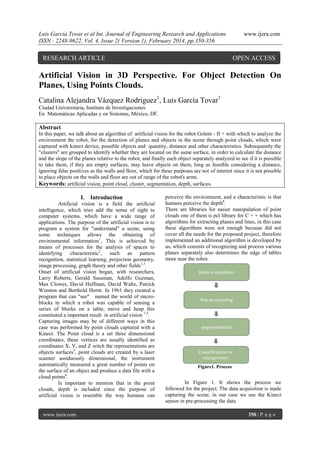
- 1. Luis García Tovar et al Int. Journal of Engineering Research and Applications ISSN : 2248-9622, Vol. 4, Issue 2( Version 1), February 2014, pp.350-356 RESEARCH ARTICLE www.ijera.com OPEN ACCESS Artificial Vision in 3D Perspective. For Object Detection On Planes, Using Points Clouds. Catalina Alejandra Vázquez Rodriguez1, Luis García Tovar1 Ciudad Universitaria, Instituto de Investigaciones En Matemáticas Aplicadas y en Sistemas, México, DF. Abstract In this paper, we talk about an algorithm of artificial vision for the robot Golem - II + with which to analyze the environment the robot, for the detection of planes and objects in the scene through point clouds, which were captured with kinect device, possible objects and quantity, distance and other characteristics. Subsequently the "clusters" are grouped to identify whether they are located on the same surface, in order to calculate the distance and the slope of the planes relative to the robot, and finally each object separately analyzed to see if it is possible to take them, if they are empty surfaces, may leave objects on them, long as feasible considering a distance, ignoring false positives as the walls and floor, which for these purposes are not of interest since it is not possible to place objects on the walls and floor are out of range of the robot's arms. Keywords: artificial vision, point cloud, cluster, segmentation, depth, surfaces. I. Introduction Artificial vision is a field the artificial intelligence, which tries add the sense of sight to computer systems, which have a wide range of applications. The purpose of the artificial vision is to program a system for "understand" a scene, using some techniques allows the obtaining of environmental information1, This is achieved by means of processes for the analysis of spaces to identifying characteristic2, such as pattern recognition, statistical learning, projection geometry, image processing, graph theory and other fields1,3. Onset of artificial vision began, with researchers, Larry Roberts, Gerald Sussman, Adolfo Guzman, Max Clowes, David Huffman, David Waltz, Patrick Winston and Berthold Hornt. In 1961 they created a program that can "see" named the world of microblocks in which a robot was capable of sensing a series of blocks on a table, move and heap this constituted a important result in artificial vision 7,4. Capturing images may be of different ways in this case was performed by point clouds captured with a Kinect. The Point cloud is a set three dimensional coordinates, these vertices are usually identified as coordinates X, Y, and Z witch the representations are objects surfaces5, point clouds are created by a laser scanner assiduously dimensional, the instrument automatically measured a great number of points on the surface of an object and produce a data file with a cloud points6. Is important to mention that in the point clouds, depth is included since the purpose of artificial vision is resemble the way humans can www.ijera.com perceive the environment, and a characteristic is that humans perceive the depth8. There are libraries for easier manipulation of point clouds one of them is pcl library for C + + which has algorithms for extracting planes and lines, in this case these algorithms were not enough because did not cover all the needs for the proposed project, therefore implemented an additional algorithm is developed by us, which consists of recognizing and process various planes separately also determines the edge of tables more near the robot. Figure1. Process In Figure 1. It shows the process we followed for the project. The data acquisition is made capturing the scene, in our case we use the Kinect sensor in pre-processing the data. 350 | P a g e
- 2. Luis García Tovar et al Int. Journal of Engineering Research and Applications ISSN : 2248-9622, Vol. 4, Issue 2( Version 1), February 2014, pp.350-356 The initial point cloud is between 35000 and 40000 points, each with values in XYZ Cartesian plane, then process the image to get less information between 10500-12000 points about which are representative to distinguish the content of the scene, and discarded surfaces and objects that are far away from the robot's arms, removing the floor and walls and large objects. In the segmentation identifies the position of the surfaces and objects and their distance and size to later save the objects found in each of the surfaces and information. Classification or recognition: for this study was conducted recognition, it is not a trained system. This system recognizes characteristics of surfaces and objects in the environment. www.ijera.com In a scene many things have the characteristic of being surfaces or at least a part of them, floors, walls, tables, chairs, bookcases, shelves, etc., But not everyone has the ability to support objects about them, for it arises an algorithm that recognize booksellers, shelves, tables in the environment and then assess whether they are empty or have objects about them, the robot does not have a database which can be a table or shelf or objects, this algorithm recognizes characteristics that define the surfaces. The recognition of surfaces begins with the capture of the point cloud in the environment by kinect device. Figure 1.1 shown capture, in this case used values of point cloud in X, Y and Z, after making the capture of the point cloud the next step is filtering through VoxelGrid function. Figure 1.2, getting less information but representative. II. Detection of planes and objects in the environment. Figure 1.1 original point cloud Figure 1.2 filtered point cloud Captured surfaces through point clouds, have the characteristic of having a constant distance in their points, while the desired objects are recognized on these surfaces identified above. Objects are identified by an interruption of points on the surface which are contained, los which also have a constant distance points, but not necessarily flat, some objects like boxes have that feature but is generally intended to identify objects with different shapes. If in surface, there is no interruption in point cloud means that it is an empty surface, but it is useful to place objects on it. Figure 1.3 show various surfaces, in this case the table is the surface searched, because contains objects which cause an interruption in certain regions of the surface, in Figure 1.4 shown clearly when object interrupted the sequence of points cloud. Figure 1.3 Surface objects www.ijera.com Figure 1.4 Surface object extraction after 351 | P a g e
- 3. Luis García Tovar et al Int. Journal of Engineering Research and Applications ISSN : 2248-9622, Vol. 4, Issue 2( Version 1), February 2014, pp.350-356 1.1 Extraction of planes Figure 1.1.1 shows a cloud of points, where one can observe a table, which is the point of interest Figure 1.1.1 Cloud point of a scene of the image, but there is noise: floor, walls and too many background objects. Figure 1.1.2 Extraction of surface and objects in the scene with noise The only vertical surface at a distance feasible considering the scope of robot arms is the table in the center of the image, which contains objects on it. In Figure 1.1.2 is an extraction of the only surface which has the characteristics. When there are many surfaces that meet the requirements, each processed separately with their corresponding information, their attributes, referring to attributes, the distance and slope with respect to the origin and the objects that are contained on the surface, if they exist, for in this way have the information individually, the robot approaches the surface in search of objects, always begins with the closest, analyzes it contains objects and then how many and if possible take them and continue with the next carrying out the same process and so on until the end with all including empty surfaces because in Figure 1.2.1 Restriction of angle and distance. 1.3 Contours Having all the point cloud is unnecessary, after removing its contents, searching for the contour of the surfaces, so she processed the cloud points of the surfaces encountered and we are left with only the www.ijera.com www.ijera.com occasions is required placing objects on them. 1.2 Restriction of angle and distance. When it reaches a point near to the table is stops and rotates 45° the robot vision device, where Z represents the depth and Y the height. In this way all the planes that are at 45 ° to the origin, with an error of plus or minus 5° will be considered as a plane, as shown in Figure 1.2.1. The walls do not comply with this restriction, because the approximate angle with respect to the origin is 135°. Thus ruling out the walls as possible planes. In the case of the floor if it complies with this restriction, but not with the distance, calculating the center of the planes obtained is discarded to the floor as it is not a prudent distance in order to place objects on it. The maximum distance is 1.30m to consider a reachable surface. Figure 1.2.2 Angle to the origin. perimeter, so the processing will be much faster to process only the necessary information. The pcl library has some functions for extraction of contours, one of which is the convex hull which is to find the outer contour of an image giving little information on the shape of which is 352 | P a g e
- 4. Luis García Tovar et al Int. Journal of Engineering Research and Applications ISSN : 2248-9622, Vol. 4, Issue 2( Version 1), February 2014, pp.350-356 extracting the outline when it is a square area of the convex hull tends to return only the corners of said surface. Using concave hull function is obtained the inner contour of the surface to be processed, thereby obtaining more defined contour that provides more information about the surface being analyzed. Through testing the convex hull function and concave hull of pcl library, extracted edges of different surfaces, rectangular, square, round and asymmetric, finally concluding that through the concave hull function provides more information to work, as seen clearly in Figure 1.3.1 the surface perimeter drawn by several points. After obtaining the contour of the surface, we want to know which is the closest side with respect to the robot, with algorithm pcl Figure 1.3.1 contour plane 𝚫𝒙 (2). Figure 1.2.2 show the angle with respect to the X axis, this angle is needed to position the robot facing the surface without collision, because not all surfaces are parallel to the axis of X. 1.5 Clusters of objects of the same surface After save each surface individually with their respective information is grouped everything www.ijera.com SACMODEL_LINE for c + + can be extracted separately lines that form the perimeter of the surface, as shown in Figure 1.3.2 where one can see two vertical lines, these are the lines that make up the front and back of the surface, then we process the lines in order to determine which one is the nearest to the robot, analyzing the entire line of the point cloud, for each position of the remaining points in the XYZ coordinates and obtain the minimum value of each vertical line in depth, in this way we will know what is nearest part by direct comparison finding the point with the lowest value in the Z coordinate about the origin. In this case the origin is the kinect device, which is mounted on top of the robot, after getting the front of the table this information will be the one used for subsequent calculations. Figure 1.3.2 vertical lines on the surface contour 1.4 Slope The slope is needed to determine in which position the plane is obtained, and to calculate the degree of inclination with respect to a straight axis on the X axis with reference to the Cartesian plane. It is noteworthy that considers the front, calculated in the preceding step. The slope calculated by the Formula (1). 𝚫𝒚 𝒎= (1). Calculate the slope angle. Formula (2). 𝜽 = 𝐚𝐫𝐜𝐭𝐚𝐧 𝒎 www.ijera.com this about it in a cluster, defining cluster as a group they belong to various objects found on the same surface. Figure 1.5.1, this to separate each surface and its objects because sometimes there are objects that seem to belong to one but they are from another or simply noise. Now that the false positives have been discarded, the clusters created are analyzed separate for extraction of each of its components. Figure 1.5.2. Now check is necessary that satisfies the required dimensions, if it is very large objects should not be considered because they can't be taken by the robot arm, it is also necessary evaluate the surface, when the robot is positioned in front of her, because on occasion there are objects that continue outside their range because they are at the other end of the table, at a distance greater than can reach his arm, distance was calculated with the formula (3). 𝒅 𝑷 𝟏, 𝑷 𝟐 = 𝒙 𝟐 − 𝒙 𝟏 + (𝒚 𝟐 − 𝒚 𝟏 ) (3). 353 | P a g e
- 5. Luis García Tovar et al Int. Journal of Engineering Research and Applications ISSN : 2248-9622, Vol. 4, Issue 2( Version 1), February 2014, pp.350-356 Figure 1.5.1 set of objects www.ijera.com Figure 1.5.2 segmented objects set III. Results The algorithm is able to process the robot environment while still analyzing the scene, because in one thread of processing and other is "watching", this is important because if it stops "see" the environment, the robot could lose detail of the possible points of interest, also approach when encountered surfaces, the robot algorithm must calculate in real time the distance the robot has about the target and when is near to the surface calculates the slope to define the angle having kinect device WITH RESPECT the axis X , can thus be placed facing the surface without collision although the surface is not completely parallel to the axis X, or one irregular surface. When they encounter various surfaces in the scene, begin to analyze the closest, later analyze those more distant and by labeling each with a number automatically assigned in ascending depending on the distance from the origin. In Figure 2.1 we can see the result of an analyzed scene after removing possible noise and process each plane separately, right of Figure 2.1 we can see the results they unfurled the vision system which clearly observed 2 planes with their respective objects, where objects 1_1 and 1_2 correspond to the plane 1, while objects 2_1 and 2_2 correspond to the plane 2. Figure 2.1 Result of artificial vision algorithm for robot 3D Golem-II + The results are shown more clearly in the graphic 1 and 2 in the first, the blue line is used for www.ijera.com artificial lighting, red for natural lighting and direct lighting solar green line. 354 | P a g e
- 6. Luis García Tovar et al Int. Journal of Engineering Research and Applications ISSN : 2248-9622, Vol. 4, Issue 2( Version 1), February 2014, pp.350-356 www.ijera.com 100 95 90 Artificial Lighting 85 Natural Lighting 80 Lighting Direct 75 70 black objects Plastic items metal objects Ceramic objects Cardboard objects Graphic 1. Object detection In the graphic 2 describes the system behavior in the recognition of surfaces, the blue line describes the vision system behavior when the lighting is artificial, the red line to the results with natural light (sunlight) and green line where direct lighting is (solar) on the surfaces. 100 98 96 94 92 Artificial Lighting 90 Natural Lighting 88 Lighting Direct 86 84 82 80 metal surfaces Plastic Planes Wooden Planes Graphic 2. Detection surfaces. As can be seen in the graphic 1 the direct illumination, shows percentage lower of correct identification of objects, this is because the light intensity prevents some parts of the object are detected by the device kinect as occasionally become reflexive depending on the material, with sun. With any type of lighting the objects black and plastic transparent, have the lowest percentage of recognition, because not census all its surface, then its size becomes very small and irregular and does www.ijera.com not satisfy the characteristics of an object in this case by direct sunlight is achieved superior recognition with respect to the other illuminations. The results for surfaces are shown in the graphic 2. For surfaces also tested with different lighting, artificial light and natural light is very similar to the percentage of recognition in the metal surfaces of 94%, with natural lighting and artificial lighting 96%. With direct solar illumination of 86% recognition on metal surfaces, 90% for plastic 355 | P a g e
- 7. Luis García Tovar et al Int. Journal of Engineering Research and Applications ISSN : 2248-9622, Vol. 4, Issue 2( Version 1), February 2014, pp.350-356 surfaces and 90% for wood surfaces. This is because direct illumination makes them reflective surfaces depending on the material the same way as with objects, with kinect device can't take all points because the light and reflection cause not detecting points. For the purpose the algorithm used, does not affect the direct illumination, due to the implementation and use of this algorithm is perform activities in indoors, however were tested and showed results obtained with these variations, for future implementations. IV. Source / / restriction horizontal planes pcl::PointCloud<pcl::PointXYZ>::Ptr lines pcl::PointCloud<pcl::PointXYZ> ()); seg1.setEpsAngle (pcl::deg2rad(45.0)); seg1.setInputCloud (cloud_model); pcl::ExtractIndices<pcl::PointXYZ> extract1; extract1.setInputCloud (cloud_model); (new / / restriction nearest line double max_x = -1.79769313486232, max_z = 1.79769313486232; double min_x = 4.94065645841247, min_z = 4.94065645841247; for (size_t i = 0; i < lines->points.size (); ++i) { if (min_x > lines->points[i].x) { min_x = lines->points[i].x; } if (max_x < lines->points[i].x) { max_x = lines->points[i].x; } if (min_z > lines->points[i].z) { min_z = lines->points[i].z; } if (max_z < lines->points[i].z) { max_z = lines->points[i].z; } } //Slope double slope, v_x, v_z, arc; v_x=max_x-min_x; v_z=max_z-min_z; slope=v_z/v_x; double tan; tan=atan (slope); arc=tan*(180/pi) pcl::compute3DCentroid (**it2, centroid2); std::cout << "The distance of line " << h << " is " << centroid2 << std::endl; V. Conclusions Machine vision has many applications, some are robotics, medical care, security, and industry, and every day is simpler with the tools that constantly appear facilitating pre-processing, segmentation, classification and recognition. Also are increasingly devices, for example various types of cameras, sensors and so on. Lighting plays an important role in artificial vision using point clouds, this is because if the illumination is directly on surfaces and objects, will be made incomplete capture of their points. In this project, natural lighting does not cause problems because the activities performed by the robot always performed indoors, where is artificial lighting. The vision 3D Algorithm designed for robot Golem-II +, recognizes objects and surfaces in an environment, separating each to extract its characteristics such as position and distance with precision close to 95% because there reflective objects that recognition decrease. Images captured from metal objects, as well as black colored objects, has difficulty identifying them as a point cloud, as in the tests recorded a significant decrease in the clouds points of these objects. In the case of transparent plastic bottles are undetected points. Bibliography [1] [2] [3] [4] [5] [6] [7] [8] [9] [10] // surface center Eigen::Matrix< float, 4, 1 > centroid2; www.ijera.com www.ijera.com Nicholas Ayache: Artificial Vision for Mobile Robots, (1999). Angel Sanchez Calle: Aplicaciones de la vision artificial y la biometria informatica, DYKINSON, S.L. (2005). Learning OpenCV. Gary Bradski; Adrian Kaehler , (2008). Y. Ma, S. Soatto, J. Kosecka, S.S. Sastry. An invitation to 3D vision. Springer, (2006). R. Szeliski. Computer Vision: Algorithms and Applications, (2003). R. M. Haralick y L. G. Shapiro, “Computer and Robot Vision (Vol. II)”. AddisonWesley, (1993). O. Faugeras, “Three dimensional computer vision: a geometric viewpoint”. MIT Press, (1993). D. H. Ballard y C. M. Brown, “Computer Vision”. Prentice-Hall, (1982) Russ, The Image Processing Handbook. CRC Press. 1992. Javier González Jiménez."Visión por Computador", Editorial Paraninfo(1999) 356 | P a g e