FPGA Implementation of QAM Transmitter and Receiver
•
0 recomendaciones•275 vistas

This document describes the design and implementation of a QAM transmitter and receiver using an FPGA. It includes: 1) A block diagram and description of the QAM transmitter design including a data sampler, phase accumulator, symbol mapper, and NCO. 2) A block diagram and description of the QAM receiver design including a phase locked loop, symbol demapper, and clock distributor. 3) Details on the carrier synchronization and timing synchronization implemented, including a phase locked loop with a phase accumulator used for carrier recovery. 4) Simulation results showing the design was successfully simulated, synthesized for an FPGA, and verified on an FPGA board.

Recomendados
Recomendados
Más contenido relacionado
La actualidad más candente
La actualidad más candente (20)
Destacado
Destacado (20)
Similar a FPGA Implementation of QAM Transmitter and Receiver
Similar a FPGA Implementation of QAM Transmitter and Receiver (20)
FPGA Implementation of QAM Transmitter and Receiver
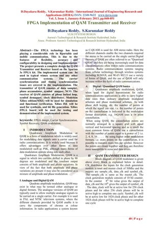
- 1. D.Dayakara Reddy, S.Karunakar Reddy / International Journal of Engineering Research and Applications (IJERA) ISSN: 2248-9622 www.ijera.com Vol. 3, Issue 1, January-February 2013, pp.048-051 FPGA Implementation of QAM Transmitter and Receiver D.Dayakara Reddy, S.Karunakar Reddy VLSI SYSTEM DESIGN Aurora's Technological & Research Institute Hyderabad, India Assoc. Professor Aurora's Technological & Research Institute Hyderabad, India Abstract—The FPGA technology has been as C-QUAM is used for AM stereo radio. Here the playing a considerable role in Rportable and different channels enable the two channels required mobile communication. This is due to the for stereo to be carried on the single carrier.Digital features of flexibility, accuracy and formats of QAM are often referred to as "Quantised configurability in designing and Implementation. QAM" and they are being increasingly used for data The project presents a complete design for QAM communications often within radio communications Transmitter and Receiver based on the Spartan systems. Radio communications systems ranging 3e FPGA kit. The implemented system can be from cellular technology through wireless systems used in typical wimax system and any other including WiMAX, and Wi-Fi 802.11 use a variety communication systems. The carrier of forms of QAM, and the use of QAM will only synchronization and timing synchronization increase within the field of radio communications. issues are covered in the implementation. The A. Digital / Quantised QAM basics transmitter of QAM consists of data sampler, Quadrature amplitude modulation, QAM, phase accumulator, symbol mapper, NCO. The when used for digital transmission for radio receiver of QAM consists of phase locked loop, communications applications is able to carry higher symbol demapper, clock distributer. Modelsim data rates than ordinary amplitude modulated Xilinx edition(MXE) will be used for simulation schemes and phase modulated schemes. As with and functional verification. Xilinx ISE will be phase shift keying, etc, the number of points at used for synthesis, and bit file generation. Xilinx which the signal can rest, i.e. the number of points FPGA board will be used for testing and on the constellation is indicated in the modulation demonstration of the implemented system. format description, e.g. 16QAM uses a 16 point constellation. keywords: FPGA design, Carrier Synchronization, When using QAM, the constellation points are Symbol Recovery, QAM modulation; normally arranged in a square grid with equal vertical and horizontal spacing and as a result the I INDRODUCTION most common forms of QAM use a constellation Quadrature Amplitude Modulation or with the number of points equal to a power of 2 i.e. QAM is a form of modulation which is widely used 2, 4, 8, 16 . . . . By using higher order modulation for modulating data signals onto a carrier used for formats, i.e. more points on the constellation, it is radio communications. It is widely used because it possible to transmit more bits per symbol. However offers advantages over other forms of data the points are closer together and they are therefore modulation such as PSK, although many forms of more susceptible to noise and data errors. data modulation operate along side each other. Quadrature Amplitude Modulation, QAM is a II QAM TRANSMITTER DESIGN signal in which two carriers shifted in phase by 90 Block diagram of QAM modulator is given degrees are modulated and the resultant output above every block is explained below in detail. consists of both amplitude and phase variations. In Clk_distributor the inputs for the clock generation view of the fact that both amplitude and phase module is reset and master clock of 50Mhz and the variations are present it may also be considered as a outputs are sample_clk, data_clk and symbol_clk. mixture of amplitude and phase modulation. The sample_clk is same as the master_clk. The clock generation module consists of 10 bit counter. I Analogue and Digital QAM In the counter 8th bit value gives the output of Quadrate amplitude modulation, QAM may data_clk and the 10th gives the output of symbol_clk exist in what may be termed either analogue or . The data_clock will be at active low for 256 clock digital formats. The analogue versions of QAM are pluses and for other 256 clock pluses will be in typically used to allow multiple analogue signals to active high to complete one cycle. Symbol_clk will be carried on a single carrier. For example it is used be at active low for 1024 clock pluses and for other in PAL and NTSC television systems, where the 1024 clock pluses will be in active high to complete different channels provided by QAM enable it to one cycle carry the components of chroma or colour information. In radio applications a system known 48 | P a g e
- 2. D.Dayakara Reddy, S.Karunakar Reddy / International Journal of Engineering Research and Applications (IJERA) ISSN: 2248-9622 www.ijera.com Vol. 3, Issue 1, January-February 2013, pp.048-051 and 3rd bit are asumed as Q bits, these I bits and Qbits are assumed as address to 3 bit Rom block’s in this according to Rom address data in that address will be given to the next block called as multipler’s. I bits are multipled with cos_in bits and Q bits are multipled with sin_in bits than resultant output’s of the multipler section will be added which generates the final output as QAM_mod_signal. III QAM RECEIVER DESIGN Rst is used to clear or reset module, data_clk will be four times faster then symbol_clk_4bit When rst is active high then left shift register will be cleared, if rst is active low with raising edge of data_clk then data_in will be forced on to the LSB bit of left shift register. Left shift register will be shifter one bit. Raising edge of symbol_clk_4bit then left shift register will be reflected on the output sampled_4bit. Clk is used for synchronication and rst is used to The system generator library provides a demo for clear two registers that are phase increment registrer QAM baseband demodulator which consists of two and phase register. The phase increment register main blocks: Carrier recovery and Symbol stores the instantaneous phase_inc_word that is fed to a 8 bit adder as one of its input. The other input demapper. Fast computing techniques using for adder is phase register output. The phase register CORDIC is employed to correct the phase error. holds the instantaneous phase for each clock pulse The adaptive algorithm does work to minimize (i.e adder output). The accumulated phase also is errors. However, because of these features, this also 8 bits, which limits the maximum phase by design cannot be applied to deep fading channels phenomenon. 11111111, and addition by 1 to maximum value causes the phase to become 00000000 PHASE LOCKED LOOP SIN AND COS LUT'S According to the address given the predefined data stored in 8 bit rom will reflected on the output pin Amp_Bits. This is expected and desired since the Look Up Tables are programmed to consider 255 as highest phase value and phase increment by one results next cycle of waveform. Since 8 bits are used to represent the 0O to 360O the increment in digital phase value by one causes effective increment of 1.40625O (results by dividng 360O with 256 maximum possible combinations of 8 bits) . This also implies that outputs can’t have more that 256 samples for one cycle. Phase locked loop is used to correct the signal at SYMBOL MAPPER demodulator it’s plays a key role in demodulation. This incremented phase is multipled with The carrier recovery can be done by using phase sin and cos for sin_lut and cos_lut respectively. The locked loop. It consists of phase accumulator. Phase resultant amplitude will be saved in the 8 bit Rom accumulator is the combination of phase register and block. So according to address that will give phase increment register. The phase increment ampltude of sin or cos signal by using this LUT’s register stores the instantaneous phase_inc_word Sampled_4bit data is loaded in to a tempary register that is fed to a 8 bit adder as one of its input. The there 0th bit and 1st bit are assumed as I bits and 2nd other input for adder is phase register output. The 49 | P a g e
- 3. D.Dayakara Reddy, S.Karunakar Reddy / International Journal of Engineering Research and Applications (IJERA) ISSN: 2248-9622 www.ijera.com Vol. 3, Issue 1, January-February 2013, pp.048-051 phase register holds the instantaneous phase for each multiplied by Kd_prod. Addition of Ki_prod, Kd clock pulse (i.e adder output). The accumulated _prod and Kp_prod generates vout which is given phase also is also 8 bits, which limits the maximum to the system to control phase by 11111111, and addition by 1 to maximum Coefficient Generation for low Pass Noise Removal value causes the phase to become 00000000. Filter: Low Pass filter. PFIR module: The filter coefficients are generated by mat lab by given process below Start Mat lab toolboxes filter design HDL coder filter design and analysis tool (FDA tool). Open FDA tool then select as shown The package created which consist of the filter coefficients will be utilized by calling the package in to program; PFIR structure is shown in above figure. Input is taken as PFIR_in and is given to a multiplier in a loop and another input to multiplier is the filter coefficient (i) stored in the PFIR package. Result generated by the multiplier will be added with another multiplier in the loop (i+1). Loop will be running till last coefficient is multiplied and result is reflected on to output signal PFIR_out . Pid controller: Click design filter. Then the coefficients will be generated . Figure 3.3 Block diagram of PID controller The output of the system is taken as input (i.e sample_in) of pid controller as that is compared with vref to generate error signal. Pid control has three section that is integration section, differentiation section and proportional section. In Proportional section gain Kp is multiplied by error and produces Kp_prod signal but in integration section accumulation(i.e past error with present error) of the error is multiplied by gain Ki to produce Ki _prod and the subtraction of the past error from present error generated result is 50 | P a g e
- 4. D.Dayakara Reddy, S.Karunakar Reddy / International Journal of Engineering Research and Applications (IJERA) ISSN: 2248-9622 www.ijera.com Vol. 3, Issue 1, January-February 2013, pp.048-051 IV . RESULTS: performance of hardware systems but also affectivity Simulation Waveform and flexibility in design and implementation. Simulation(Modelsim6.2c), synthesis(xilinx ISE), implementation(spartan 3e) and verification of design after implementation is successfully completed. REFERENCES [1] 16 QAM transmitter and receiver design based on FPGA IEEE 2010, Xuan-thang Vu, Nguyen Anh Duc, Trinh Anh Vu [2] C. Dick, F.Harris, M.Rice, Synchronization in Software Radios-Carrier and Timing Recovery Using FPGAs, Proceeding of 2000 IEEE Symposium on Field- Programmable Custom Computing Machines. [3] C.Dick, F.Harris, M.Rice, FPGA Implementation of Carrier Synchronization for QAM Receivers, Journal of VLSI Signal Processing, Vol 36, p 57-71,2004. [4] Joaquin Garcia, Rene Cumplido, On the design of an FPGA-Based OFDM modulator for IEEE 802.11a, Proceeding of ICEEE, September 7-9, 2005, Mexico. [5] John G. Proakis, Digital Communication, McGraw-Hill 1993. [6] VLSI for Wireless communication, Bosco Luen Pearson Education and VLSI series [7] http://www.xilinx.com V. CONCLUSIONS A computationally efficient algorithm is developed for a low power and versatile ASIC design of QAM transmission system. Utilization of this algorithm in the development of mobile and portable communications requires not only high 51 | P a g e