O41049497
•
0 recomendaciones•262 vistas

International Journal of Engineering Research and Applications (IJERA) is an open access online peer reviewed international journal that publishes research and review articles in the fields of Computer Science, Neural Networks, Electrical Engineering, Software Engineering, Information Technology, Mechanical Engineering, Chemical Engineering, Plastic Engineering, Food Technology, Textile Engineering, Nano Technology & science, Power Electronics, Electronics & Communication Engineering, Computational mathematics, Image processing, Civil Engineering, Structural Engineering, Environmental Engineering, VLSI Testing & Low Power VLSI Design etc.

Recomendados
Recomendados
Más contenido relacionado
Destacado
Destacado (20)
Similar a O41049497
Similar a O41049497 (20)
Último
Último (20)
O41049497
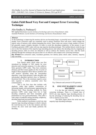
- 1. Alin Sindhu A et al Int. Journal of Engineering Research and Applications ISSN : 2248-9622, Vol. 4, Issue 1( Version 4), January 2014, pp.94-97 RESEARCH ARTICLE www.ijera.com OPEN ACCESS Galois Field Based Very Fast and Compact Error Correcting Technique Alin Sindhu.A, Pratheep.G ME Applied Electronics Loyola institute of technology and science Kanyakumari, india Assistant Professor, Loyola Institute of Technology and Science Kanyakumari, India Abstract As the technology is improving the memory devices are becoming larger, so powerful error correction codes are needed. Error correction codes are commonly used to protect memories from soft errors, which change the logical value of memory cells without damaging the circuit. These codes can correct a large number of errors, but generally require complex decoders. In order to avoid this decoding complexity, in this project it uses Euclidean geometry LDPC codes with one step majority decoding technique. This method detects words having error in the first iteration of the majority logic decoding process and reduces the decoding time by stopping the decoding process when no errors are detected as well as reduces the memory access time. And the result obtained through this technique also proves that it is an effective and compact error correcting technique. Key Words-Error correction codes, Euclidean geometry low density parity check codes, memory, majority logic decoding. I. INTRODUCTION Low density parity check codes was first introduced by Gallager in 1962 mainly for error detection and correction purposes. It is also called as finite geometry LDPC codes. They have minimum distances and their tanner graphs are free of cycles of length 4.These properties allow them to perform well with iterative decoding using the sum-product algorithm. Long finite-geometry codes decoded with sum-product algorithm perform close to Shannon‟s theoretical limit. This is the minimum signal to noise ratio required to achieve essentially error free communication. This is the first class that includes with algebraic, rather than random, construction of increasing lengths with performance approaching the Shannon limit. These decoding methods for finite geometry LDPC codes range from low to high decoding complexity and from reasonably good performance to very good performance. They offer a wide range of tradeoffs among decoding complexity, decoding speed and error performance. In this method it accelerates a serial one step majority logic decoding technique in which it detects the word having error in the first iteration and then corrects the error word and finally performs the decoding www.ijera.com Encoder Memory . Detector Decoder Corrector Fig 1.Detector and corrector in EG geometry II. ONE STEP MAJORITY LOGIC DECODING It is the fast and relatively compact error correcting technique. There is a limited class of ECCS one step majority logic decoding process. It has the advantage of reducing the decoding time as well as memory access time. The below figure shows the serial one step majority logic decoding technique. 94 | P a g e
- 2. Alin Sindhu A et al Int. Journal of Engineering Research and Applications ISSN : 2248-9622, Vol. 4, Issue 1( Version 4), January 2014, pp.94-97 Fig 2.Serial one step majority logic decoder for (15,7) EG hamming code The two basic steps involved in calculating the detected codeword are as follows: 1) Generate parity check sums by computing the inner product of the received vector and the appropriate rows of parity check matrix. 2) The check sums are fed into a majority gate. The output of the majority gate corrects the bit by inverting the value if the output of majority gate is “1”. The serial majority corrector takes cycles to correct an erroneous codeword. If the fault rate is low, the corrector block is used infrequently; since the common case is error-free code words, the latency of the corrector will not have a severe impact on the average memory read latency. The one step majority logic detector can be used to correct all the n bits of the received codeword of a cyclic code. To detect each code bit, the received encoded vector is cyclic shifted and fed into the XOR gates. The information bits are fed into the encoder to encode the information vector. The fault secure detector of the encoder verifies the validity of the encoded vector. If the detector detects any error the encoding operation must be redone to generate the correct codeword. The codeword is then stored in the memory. During memory access operation, the stored codeword‟s will be accessed from the memory unit. A corrector unit is designed to correct potential errors in the retrieved codeword‟s. MLD is based on a number of parity check equations which are orthogonal to each other, so that at each iteration each codeword bit participates in one contributes to all equations. For this reasons the majority result of these parity check equations decide the correctness of the correct bit under decoding. Generic schematic of a memory system is depicted for the usage of an ML decoder. www.ijera.com www.ijera.com In this method initially, the data words are encoded and then stored in the memory the resulting sums are then forwarded to the majority gate for evaluating its correctness. If the number of 1‟s received in is greater than the number of 0‟s, which would mean that the current bit under decoding is wrong and a signal to correct it would be triggered. Otherwise, the bit under decoding would be correct and no extra operations would be needed on it and it increases decoder. However they require a large decoding time that impacts memory performance. In order to improve the decoder performance, alternative designs may be used. One possibility is to add a fault detector by calculating the syndrome, so that only faulty code words are decoded. Since most of the codeword will be error free, no further correction will be needed therefore performance will not be affected. Although the implementation of an SFD reduces the average of the decoding process. A. Encoder Fig 3.Encoded data from encoder (7-bits of information) In encoder the input bit of 7bits of information is encoded .It produces encoded bits in which it has information as well as parity check bits .These parity bits are responsible for detecting the presence of error and hence correct the erroneous word. The outputproducedwillbeencodedbitsc1,c2,c3,c4,c5,c6,c 7,c8,c9,c10,c11,c12,c13,c14.In general the encoder transfers the following input information to the memory. Here the input is the 7-bits of information, and then the encoded input is stored in the memory devices of the electronic devices. B .Detector & Corrector The basic operation of the detector is to generate the syndrome vector. This is obtained by a 95 | P a g e
- 3. Alin Sindhu A et al Int. Journal of Engineering Research and Applications ISSN : 2248-9622, Vol. 4, Issue 1( Version 4), January 2014, pp.94-97 matrix multiplication on the received coded vector c and the transpose of the parity check matrix H, S=C*(H^T) www.ijera.com D. Flowchart for MLD START 15-Bits of data (encoded bits) Calculate syndrome Fig.4.Fault secure detector for (15, 7, 5) EG-LDPC codes The encoded bits and one row of the parity check matrix is multiplied to get the syndrome vector .If the calculated syndrome consists of the presence of ones, then an error is believed to have occurred. All zeros indicate no error. The vector matrix multiplication is implemented with the help of XOR gates. The input to these gates depends on the weight of parity check matrix. If the weight is assumed to be p then p input XOR gates are required. Else two (p-1) input gates is required. As shown in the above diagram, each syndrome bit is calculated using separate XOR gates. Therefore there is no logic sharing in the detector implementation and hence is a fault secure detector. The final error detection signal is implemented by an OR function of all the syndrome bits. The output of this n-input OR gate is the error detector signal. C. Decoder In the decoder the corrected bits are decoded. In general the decoder recovers the original data which is send by the sender. The input of the decoder is totally 15-bits of data in which it consists of 7bits of information and 8 bits of encoded bits. This recovery is based on Euclidean geometry which means distance between 1‟s must be small. According to this geometry it selects the information bits and performs the XOR operation. Hence the output will be the error free information bits. www.ijera.com Check if syndrome is zero Find error location 7-bit data (Recovery of information bits) STOP Fig 5 flow chart for MLD The 15-bits of data is given as output to decoder. These 15 bits of data consists of 7bits of information bits and 8 bits of parity bits. Then calculate the syndrome bits and check whether the syndrome bit is “1” or “0”.If the syndrome bit is “0” then it is considered to be error free whereas if the syndrome bit is “1” then it is considered to be error. 96 | P a g e
- 4. Alin Sindhu A et al Int. Journal of Engineering Research and Applications ISSN : 2248-9622, Vol. 4, Issue 1( Version 4), January 2014, pp.94-97 III. APPLICATIONS Data storage devices Wireless cellular network Satellite broadcast IV. EXPERIMENTAL RESULTS They are used in every device which consists of memory .They are used in the following applications: encoders and decoders are required. Accounting for all the above area overhead factors, all the codes considered here achieve memory density of 20 to 100 GB/nm, for large enough memory (0.1 GB). REFERENCES [1] [2] [3] [4] [5] Fig. 6 Stimulated waveform [6] Fault secure detectors detects fault in the encoded bits .If fault is detected the encoding operation is redone. So the core operation of the FSD is to find the syndrome vector .So first the generator matrix is generated and its transpose is found. Then the syndrome vector is found. Then the syndrome vector is found by multiplying the coded bit with the transpose of parity check matrix. Now if all the bits of syndrome vector are „0‟ then there is no fault the parity check matrix. Now if all the bits of the syndrome vector are „0‟ then there is no fault. V. CONCLUSION A fully fault-tolerant memory system is presented that is capable of tolerating errors not only in the memory bits but also in the supporting logic including the ECC encoder and corrector Euclidean Geometry codes are used. These codes are part of a new subset of ECCs that have FSDs. Using these FSDs a fault-tolerant encoder and corrector is designed, where the fault-secure detector monitors their operation. A unified approach to tolerate permanent defects and transient faults is explained. This unified approach reduces the area overhead. Without this technique to tolerate errors in the ECC logic, reliable (and consequently lithographic scale) www.ijera.com www.ijera.com [7] [8] [9] [10] De Hon. J “Deterministic addressing of nano scale devices assembled at sublithographic pitches” vol.4 no6 IEEE trans. nano technology,2005. Kim.j and Kish.L “Error rate in currentcontrolled logic processors with shot noise” vol.4 no.1 IEEE trans, 2004. Kou.Y and Lin.S “Low density parity check codes based on finite geometries” vol.47 no.7 IEEE trans,2001. Lin.S and Costello.D.J “Error control coding” vol.40 no.2 IEEE trans,2004. Liu.S,Reviriego.P and Maestro.J “Efficient majority logic fault detection with difference-set codes for memory applications” vol.20 no.1 IEEE trans ,2012. Naeimi.H “A greedy algorithm for tolerating defective cross points in nano PLA design” vol.21 no1 IEEE trans,2005 Sun.F and Zhang Jun.T “Defect and transient fault-tolerant system design for hybrid CMOS/nano technology ” vol.6,no.3,IEEE trans 2007. Tang.H, Xu.J, Lin.S and Abdel-Ghaffar.K “Codes on finite geometries” vol.51,no.2,IEEE trans 2005. Vasic.B and Pedagani.K “Run length limited low density check codes based on deliberate error insertion” p.453,IEEE trans 2004. Varnica.N and Kavcic.A “Optimized LDPC codes for partial response channels” p.197,IEEE trans 2002. AUTHORS PROFILE Alin Sindhu.A Pursuing M.E(Master of Engineering) in Applied Electronics From Loyola Institute of Technology and Science. Received her B.E in Electronics and Communication Engineering from CSI Institute of technology, Anna University. Her areas of interest include VLSI design. 97 | P a g e