UGM 2015: X1149 workshop
•Descargar como PPTX, PDF•
2 recomendaciones•629 vistas

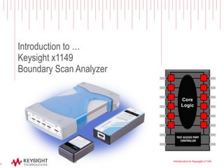
Introduction to Keysight x1149 Boundary Scan Analyzer

Recomendados
Recomendados
Más contenido relacionado
La actualidad más candente
La actualidad más candente (20)
Destacado
Destacado (12)
Similar a UGM 2015: X1149 workshop
Similar a UGM 2015: X1149 workshop (20)
Más de Interlatin
Más de Interlatin (20)
Último
Último (20)
UGM 2015: X1149 workshop
- 1. Introduction to … Keysight x1149 Boundary Scan Analyzer Introduction to Keysight x1149 1
- 2. Page COMPLETE BUNDLE AVAILABLE. • PC Controlled (Ethernet). • Four TAP/IO Boxes. - 1x TAP Port. - 4x Digital input ports. - 5x Digital output ports. • One Diagnostic Clip. • Add-on Cover-Extend Technology capability - Vectorless testing of ICs or Connectors through boundary scan • Scan Path Linker - Connecting physically separate chains to test the interconnecting nets Controller TAP I/O Boxes Diagnostic Clip Keysight Restricted 2
- 3. Page TAP#4 CET Adaptor110-240V USB to PC *USB *Trigger Out LAN to PC *RS-232 *reserved for future use 4 programmable 0-5V receivers IEEE 1149.1 TAP TCK : programmable 0-5V, 40-380V/us, max 22.5MHz TMS : programmable 1.1-5.0V, max 7.5MHz TRST : programmable 1.1-5.0V, max 10KHz TDI : programmable 1.1-5.0V, max 11.25MHz TDO : programmable 0-5V, max 11.25MHz 1 VCC 4 GND TAP#3 TAP#2 TAP#15 programmable 1.1-5.0V drivers LAN to PC
- 4. Page x1149 CET Mux Power Adaptor LAN to PC x1149 TAP/IO x1149 Controller No test access Cover Extend Technology uses Boundary Scan as the stimulus to test non-Boundary Scan components having no test access. VTEP amplifier, sensor plate and a Cover-Extend Mux is required to complete the metrology. VTEP amplifier & sensor plate Keysight Restricted 4
- 5. Page Keysight x1149 TCK set at • 3V • 22.4MHz • @ 300V/us Compared with ‘ABC’ Scan TCK set at • 5V • 15.8MHz • ? V/us (not adjustable) Keysight x1149 TCK set at • 3V • 1.8MHz Keysight x1149 TCK set at • 3V • 1.8MHz • @ 300V/us • @ 50V/us Adjustable Slew Rate Low overshoot Keysight Restricted 5
- 6. Page
- 7. Page Best in Class GUI • All information available on the screen at a mouse click. • Alternative language support (e.g. Chinese). More can be added with translation matrix. • Dock and un-dock screens to size displays. • Intuitive. • Comprehensive CAD format inputs or simply use i3070 board file. • Follows natural test development process • Test coverage tool, first pass yield, operator GUI, schematic viewer and more. • Three level of login privileges to manage user profiles • Enables Ease-Of-Use
- 8. Page Graphical view of the selected chain. Mouse over to retrieve the TAP information. All information of the devices in the chain at a glance. Process Outline Guides user through test development and debug. Project Explorer Navigate to sections of the test at a click. Click to select chain. Generate Multi-Chain Scan Path Linker combines chains at a click. Configure/Reconfigure Chain Automatically sets up chains using board’s net information.
- 9. Page View the failing test in Waveform Viewer or the Frame Debugger to view the expected vs actual. View failure as a waveform Keysight Restricted 9
- 10. Page View the failing test in Waveform Viewer or the Frame Debugger to view the expected vs actual. Vector view of frame Undocked view of the waveform Keysight Restricted 10
- 11. Page View the failing test in Waveform Viewer or the Frame Debugger to view the expected vs actual. Undocked view of the frame Keysight Restricted 11
- 12. Page Output Shows the results of all the tests for the chain(s). Results of tests are highlighted in colors. Test results can be sorted by clicking on the title tab. Repair Ticket Pin-level failure reporting and possible cause. Keysight Restricted 12
- 13. Page Output Shows the results of all the tests for the chain(s). Results of tests are highlighted in colors. Test results can be sorted by clicking on the title tab. Repair Ticket Pin-level failure reporting and possible cause. Board with injected open faults (Dot6 test) Keysight Restricted 13 CET test failures
- 15. Page ‘Standard’ Boundary Scan Test • Board designs can have boundary scan chains physically separated (not connected). • Such boundary chains will be generated and tested as separate chains. Scan Path Linker • Boundary scan test coverage can be increased by the number of interconnect nets if boundary scan chains can be ‘connected’ during testing and revert to its original design after testing. • x1149 Scan Path Linker connects two or more boundary scan chains by linking the TDO to the TDI of these chains inside the controller. • Automated logic level management IC IC IC IC No test coverage IC IC IC IC Nets tested Keysight Restricted 15
- 16. Page Integrated STAPL Player • STAPL (Standard Test and Programming Language) • JEDEC standard : JEDEC-JESD71 • Enables programming of various CPLD/FPGA devices from vendors like Xilinx, Altera, Lattice, Actel (Microsemi) and more. • Compiler takes in various formats : STAPL, jam, jbc, svf files Keysight Restricted 16
- 17. Page Applications for x1149 Boundary Scan Analyzer Keysight Restricted 17
- 18. Page Applications for boundary scan test (cont’d) – Testing of Mobile phones • Low cost structural test method providing pin level diagnostics in order to filter out and reduce functional defects • Test SDRAM POP on the only bscan component (CPU) • Test connectors for shorts and opens using vectorless test methods – Testing of SSD boards • Pre-functional test filters out structural defects for boards with only one Bscan IC on-board • This is a quick test that covers all functional blocks of the SSD, Controller, NAND, SDRAM, EEPROM, Temp sensors, etc • Combines structural test with some functional test. Shorts and opens test on power and ground nodes, read/write tests on NAND & SDRAM, programming of EEPROM • Tested in panels of boards Keysight Restricted 18
- 19. Page Applications for boundary scan test – Testing of Netcom boards • Large boards ~ more than 10k nodes - Want to test at ICT in order to filter out defects before functional test reduce functional test cost • Many Bscan ICs on board in long chains • Bscan is used to reduce the testpoint resources to allow board to fit on ICT – Testing Server boards • Detect shorts and opens on CPU sockets and SDRAM DIMM connectors even through there are no testpoints between the CPU and SDRAM DIMM • Silicon Nails tests are used to test the paths between the CPU & SDRAM DIMMs Keysight Restricted 19
- 20. Page Applications for boundary scan test (cont’d) – Embedded Test for Motherboards • Using built-in test capabilities on the Intel CPU, we are able to execute functional test on the peripherals • This is a quick test that provides good diagnostics, but it is dependent on the test capabilities exposed to the test developer by the Intel CPU developers • Combines structural test with functional test. Possible to reduce functional testers Keysight Restricted 20
- 21. Page Using x1149 in all stages of the Product Life Cycle Keysight Restricted 21
- 22. Page x1149 throughout the Product Cycle Keysight Restricted 22 Design R&D • Quick test turn on • Test high-value ICs • Diagnostics during design verification Warranty Repair • Field Repair • Fixtureless, portable Prototyping NPI • Quick test turn on • Test high-value ICs • Test development enhancements Mass Production Production • Leverage from NPI • Integration to ICT or Standalone • Savings on fixturing Debug Repair • Short test time • Pin level diagnostics Product Life Team Benefits
- 23. Page Conclusion Introduction to Keysight x1149 23 – Boundary Scan is the most effective means to mitigate issues with loss of test access on the product – Boundary Scan requires DFT to be most effective – Keysight produces an easy to use, manufacturing ready boundary scan tester for your production Get it NOW
- 24. UGM 2015 x1149 Boundary Scan Analyzer Workshop
- 25. Page X1149 Boundary Scan Analyzer Workshop – Development – Debug – Runtime TAP/IO Port Bravo Board x1149 CET Module x1149 Main Controller 2 1 1 2 3 3 4 5 4 5
- 26. Page Development – New Project • Add board – J6 Test CET – U3, U4 Show Silicon Nails – U3, U4 Add Flash • flash.absl - AT24C128BN_soic - AT25DF161_soic – Configure Chain – Generate Tests – Generate Test sequence
- 27. Page Debug – Set IP Address – Show Integrity test • Undock Repair Ticket – Show IDCode • View Debug Windows - Binary – Show Device Information • Set Multiple IDCode – Show Interconnect test • Framedebugger • SW2%4-5 OpenClose • Failure waveform – Show CET • Port 1 • AutoDebug CET • Run – View Graphics • SW2%2-7 – Flash Programming • U3 - Program (Partial) … 0 to 100 - Verify (Partial) … 0 to 100 - Run • U4 - Read IDCode - Chip Unprotect - Chip Erase - Blank Check - Program (Partial) … 0 to 100 - Verify (Partial) … 0 to 100 - Run – Show Test Sequence • Show Command and Test List • Add Print • Release to Production
- 28. Page Runtime – Production Run – Operator Mode • Load Tests • Admin Screen • Set IP Address • Run Keysight Confidential 28
- 29. Page Thank You! Adrian Cheong Product Marketing Manager Keysight Technologies adrian_cheong@Keysight.com Introduction to Keysight x1149 29