SlideShare una empresa de Scribd logo
1 de 22
Descargar para leer sin conexión
Design and Analysis of the Jayhawk Economic Turboprop
Transport (J.E.T.T)
AIAA Undergraduate Team Aircraft Design Competition
2013 - 2014
Brandon Basgall
Katie Constant
Eleazar Lachino
Adrian Lee
Emily Thompson
Alejandra Escalera
Instructor: Dr. Ron Barrett
Department of Aerospace Engineering
May 10, 2014
Aerospace Engineering Department 3
Mission Specification and Profile
Provided by AIAA during the fall of 2013, the following outlines the RFP guidelines to be adhered to in the
design of a new and upcoming turboprop regional airliner. The following lists the major characteristics needed to be
considered for the newly designed regional turboprop aircraft:
Table 2-1: Regional Turboprop Mission Specifications and Requirements (Ref. 2)
Economic Mission Requirements
Available Passenger Seating 75
Range 400 nautical miles
Design Mission Requirements
Available Passenger Seating 67
Range 1600 nautical miles
Additional Considerations Necessary Mission Fuel Reserves
Performance Requirements
Take-off Runway Length at MTOW 4,500 feet (or shorter)
Take-off Conditions (Altitude and Temp.) 7,800 feet at 85° F
Cruise Speed (Mach) 0.62 – 0.68
Cruise Altitude 25,000 – 31,000 feet
Fuel Consumption 65% fuel reduction from similar currently operational
regional jets
Cost
Production Run 15 years period, 400 aircraft
Total Cost Must be substantially less than currently operational
regional jets
Entry into Service 2022, minimum lifetime of 30 years
Additional Considerations
Passenger Comfort and Acceptance “Jet-like” Experience
Passenger with Baggage Weight 225 lbs
Aerospace Engineering Department 4
From the previously
defined variables to be included
in the design process of the new
regional turboprop aircraft, the
following mission profiles have
been created. Figure 2-1 shows
the defined economic mission
under normal runway
considerations of 4,500 foot
runways. From this mission
profile, it can be seen that the
cruise conditions for this profile are noted as cruise speed between Mach 0.62 and Mach 0.68 with a cruising altitude
between 25,000 and 30,000 feet.
To accommodate the requested design mission of 1,600 nautical miles carrying 67 passengers, Figure 2-1 also
displays the mission profile
for the conventional design
mission. Within this mission,
the cruise speed and altitude
will remain the same as seen
with the economic mission, as
well the same 4,500 foot
runways. With the design
range in mind, the design of
fuel reserves will be taken
into account. As designated within the RFP, the design fuel reserves will meet the FAR 25 Loiter regulations, stating
the full 45 minute loiter fuel-reserve capacity.
To be able to achieve the designated “high-hot” conditions outlined in the AIAA RFP, Figure 2-2 displays the
adjusted mission profile. To adjust for the “high-hot” conditions, the runway length will be adjusted to 8,000 feet
Figure 2-1: Design and Economic Mission Profiles of Turboprop
Aircraft
Figure 2-2: Design and Economic Mission Profiles for "High-Hot"
Conditions
Aerospace Engineering Department 9
Figure 4-3: Determination of Design Fix Date with Respect to
Variables (Ref. 1)
equation to model the distribution has been
determined, it will be placed on the same plot
as the first flight distribution.
The vector analysis process gives
engineers a tool with which they can track
and predict any vector of engineering design
variables at any given point in time. This
point can be either in the past to analyze
previous trends or in the future to see what
they should prepare for. The process makes
use of distribution curves by taking into
account all of the desired design variables for
as many aircraft, of the similar class as the
one being asked for. The following is the
procedure that was performed by the contestants to establish some of the critical design variables (Ref. 21 )
First a product timeline must be developed using aircraft of the same class as the one being designed. The
most important dates of an aircraft’s lifecycle must be researched and gathered for use. The date of first flight of the
aircraft will be plotted onto a graph and
a distribution curve will be generated to
fit the data. The peak of this, also the
highest year for first flights of aircraft
will be labeled as year zero of the
aircraft’s lifecycle. The res t of the
distribution will be positive or negative
years with respect to the reference zero.
Once this distribution has been
established the design fix date for the same aircraft, it will generate another distribution curve. Once again the year
at which the distribution reaches its peak will be labeled as zero. Once the graph has been observed and a good
Figure 4-2: Determination of Statistical Interval
Related to Rvi (Ref. 21)
Aerospace Engineering Department 13
Empty-to-Takeoff Weight Ratio, We/Wto (~)
MarketShare,(%)
1983
1984
1987
1988
1989
1990
1991
1985
1986
1992
1993
1994
1995
1996
1997
1999
1998
2000
2001
2002
2003
2004
2005
2006
2007
2008
2009
2010
2011
2012
2013
2020
0.000
0.100
0.200
0.300
0.400
0.500
0.600
0.700
0.800
0.5 0.6 0.7
PercentageofMarketShare,(%)
Empty-to-Takepff Weight Ratio We/Wto (~)
ATR-42
33%
Fairchild 37%
EMB-120
23%
F-27 5%
1986 Weight Standard Deviation
BAE ATP
2%
Figure 5-1: STAMPED Weight Analysis
Aerospace Engineering Department 16
6.2 Sizing Chart Analysis
Utilizing the STAMPED procedure for identifying a
preliminary design point, the following table is a summary of the
first iteration of design. Additional analysis and multiple iterations
through Class I and Class II design would ultimately lead to the
final design sizing selections. Figure 6-1 is a visual representation
on how the sizing values were determined. As the figure shows, by
documenting the changes through time, the design point was determined.
Figure 6-1: Statistical Time and Market Predictive Engineering Design (STAMPED) Sizing Chart Results
In addition to the STAMPED analysis, a sizing chart was constructed following the procedure outlined in
Reference 3. The results from these calculations are presented in the figure below. The results from the two methods
Area, S (ft2
) 800
Power (shp) 7530
Wing Loading (psf) 80
CLmax,clean
1.9
CLmax,landing
2.1
CLmax,TO
2.6
Table 6-1: Sizing Chart Results
Aerospace Engineering Department 18
σ = +1
σ = -1
σ = -1
σ = +1
2020
Standard
Deviation at σ
= ±1
Design
Point
W/S
Sizing Chart
W/P
W/S
PowerLoading,(W/P)TO(lbf/hp)
Take off Wing Loading (W/S)TO (lbf/ft2
)
Take off Wing Loading (W/S)TO (lbf/ft2
)
1998 Example
PowerLoading,(W/P)TO(lbf/hp)
Take off Wing Loading (W/S)TO (lbf/ft2
)
PowerLoading,(W/P)TO(lbf/hp)
W/P
Figure 6-3: STAMPED Power and Wing Loading
Aerospace Engineering Department 19
Class I Sizing
The following sections will develop the calculations completed for a class I design analysis. This section will
begin with a range of proposed configurations, followed by a down-selection to four final preliminary configuration
designs. Class I design was completed on each of these four designs the results of which determined the design best
fit for Class II analysis.
7.1 Preliminary Configuration Selection
7.1.1 Selection of the Aircraft Configuration
For this initial stage in aircraft configuration, all possible options were considered. Driving factors of
configuration selection included technical considerations such as C.G. excursion, and fuel capacity but also design
goals such as range, jet-like experience for passengers, and low procurement cost.
7.1.2 Aircraft Configurations and Merit Criteria
The following is a list of 12 different aircraft configurations that were considered by the team in the
preliminary configuration selection process. These various designs were evaluated with respect to the requirements
and objectives outlined in the RFP (Ref. 2).
Table 7-1: Air Configuration Considerations
1. Box Wing 2. Vertical/Short Take Off
& Landing (V/STOL)
3. Delta Wing 4. Conventional (High-
Wing, Conventional Tail
5. Tail Boom, Swept Wing 6. Three Surface 7. Flying Wing 8. Tandem Wing
9. Inverted Gull Wing 10. W Wing 11. Channel Wing 12. Double Fuselage
Aerospace Engineering Department 38
Figure 8-8: Isometric View of Engine Access Panel
propeller in respect to the wing was chosen specifically for geometric clearance during low speed approach with
bank angles around 5° as well as
during take-off rotation (Ref. 4).
The shroud will have 5 struts for support and
withstand the vibration generated by the propeller and engine.
Figure 8-9: Engine Removal Method
The engine removal from the shroud and nacelle will require a special pulley as shown in Error! Reference source
not found.
Figure 8-7: Side View of Shrouded Engine
Aerospace Engineering Department 41
on the ground. The following figures demonstrate the Prandtl-tailored δ3 wingtips which the team opted to
implement. Prandtl with his research found in Über Tragflügel kleinsten induzierten Winderstandes, that the wing
weight could be reduced by minimizing the moments, either creating negative bending moments to counteract the
positive moments or forcing them to approach zero (Ref. 24). Figure 8-12, from Prandtl’s Über Tragflügel kleinsten
induzierten Winderstandes shows the span loading concepts that were established with his research. Prandtl made
the following conclusions in his document: elliptical distribution of lift is disadvantageous if trying to minimize
induced drag, although the exact shape of sharp wingtips is not of high importance, sharp wingtips are advantageous
when compared to squared wingtips (Ref. 24).
Keeping in mind the conclusions drawn by Prandtl’s studies, the target wing span with wing tips folded
could grow no larger than 79 feet (Category 2 regulations). For optimal L/D, a total wing span was set at 118 feet
with an aspect ratio of 23.
Figure 8-13: Boeing 737 Clean Configuration, With Prandtl-tailored δ3 Wingtips both Extended and Folded
and Folding Mechanism (Ref. 24)
Clearly, 118 foot wing span and aspect ratio is far outside the allotted gate spacing thus need for foldable wingtips
becomes necessary to make this possible. One of the reasons why Prandtl’s concept has not been implemented in
current aircraft is the weight of the hinge and actuator to fold the wingtips (Ref. 25). While the overall performance
is increased, the added weight makes this design impractical for use. However, with the implement
ation of Pressure Adaptive Honeycomb (PAH) weight concerns are eliminated. In this application, Pressure
Adaptive Honeycomb would be used as the actuator of the wingtip and for the implementation of a δ3 hinge
ensuring that the moment at the wing tip is equal to zero or insignificant (Ref. 25). While an advanced technology,
PAH can be produced at a low manufacturing cost from aluminum and nylon pouches and can be integrated to
conventional structures in the aerospace industry while maintaining a low part count (Ref. 24). Although the
Pressure Adaptive Honeycomb can be activated by the external ambient pressure, it can be designed to actuate the
Aerospace Engineering Department 59
Figure 9-9: Carpet Plot for Wing Loading at a Specific Range
Table 9-7 : Carpet Plot Design Parameters
The carpet plot here is serving as a verification of the
design parameters selected. As Figure 9-9 shows, the
parameters selected for the design of the J.E.T.T. can be
verified and are at the optimal design point for the RFP. The
following table is a summary of the design parameters
collected from the above carpet plot.
0.298
0.3
0.302
0.304
0.306
0.308
0.31
74 76 78 80 82 84 86 88
SpecificRange,SR(nmi/lb)
Wing Loading, W/S (lbf/ft^2)
AR = 25
AR = 23
AR = 21
AR = 19
Wf = 5300 lbf
Wf = 5400 lbf
Wf = 5500 lbf
Wf = 5600 lbf
Wf = 5700 lbf
Design Point
Insufficient Fuel to reach 1600nmi
Insufficient Fuel Space on Wing
Parameter Value
Specific Range, SR (nmi/lb) 0.305
Weight of Fuel, Wf (lb) 5500
Aspect Ratio, AR 23
Lift-to-Drag Ratio, L/D 21.1
Wing Loading, W/S (lbf/ft^2) 80
Aerospace Engineering Department 60
Figure 10-1: All Systems and Subsystems of the J.E.T.T
Layout of Systems and Subsystems
All of the major systems were modeled in this aircraft which included:
 Flight Control System
 Hydraulic System
 Water and Waste System
 Environmental System
 Electrical System
 Fuel System
 De-Icing System
10.1 Flight Control System
The J.E.T.T. is equipped with an irreversible flight-by-light control system. An irreversible system was
chosen for obvious reasons and an irreversible flight control system in an aircraft of this size would be extremely
impractical and outdated. Flight-by-light was chosen in place of the more traditional fly-by-wire since the
technology is available now and will only be more advanced in years to come. As it stands currently, the optics in
fly-by-light systems require less space and in an aircraft as constrained for extra space as the J.E.T.T. this is
important. Additionally, the 18 fiber optical cables are designed to meet all environmental, mechanical and optical
requirements set for by FAR requirements (Ref. 30). For safety purposes, this system is quadruple
Aerospace Engineering Department 64
10.6 Water and Waste System
The water and waste system will be housed in the belly of the aircraft along with many of the other systems.
Waste that is produced in either the front or the rear of the aircraft will be pumped into either one of the holding
tanks which upon landing will be emptied. Since the entire fuselage will be pressured and heated, there is no concern
that water lines may freeze in this design.
10.7 Environmental System
The final system in this aircraft is the environmental system which includes the air conditioning and oxygen
system; both extremely important for day to day operations and are both doubly redundant. As was mentioned
previously, both the APU and RAT are capable of supplying power to the oxygen system if failure occurs elsewhere.
Figure 10-8: Environmental System Shown in Green Provided Oxygen and Air Conditioning
The J.E.T.T. will be equipped with an open-loop redundant cabin air conditioning and pressurization system.
For passenger comfort, the cabin will be pressured at 7,500 feet (11.1 psi) and temperatures will be maintained
around 70 degrees Fahrenheit.
Aerospace Engineering Department 65
Inboard Profiles
From the required RFP of a maximum amount of passengers to carry, the J.E.T.T. can accommodate 76
passengers with the addition of 2 flight attendants. To get this arrangement, the seating is organized with a 4-abreast
seating throughout the full cabin. This seating arrangement allows for space at the front and the aft of the cabin for a
fully functioning galley and a lavatory at the tail of the aircraft. Also, the symmetric arrangement of the seats fed
into the considerations of carry-on baggage volume, aisle width and length, as well as the ease of redesigning for
family variants in production. The following table details the specific cabin characteristics.
Table 11-1: Internal Cabin Characteristics
Inner Fuselage Diameter 102 in Number of Seats 76
Seat Pitch 20.0 in Crew Seats Attached to Aft Bulkhead Wall
Seat Width 19.5 in Galley Floor Size 39 in x 26 in
Aisle Width 19.0 in Lavatory Floor Size 39 in x 47 in
Maximum Aisle Height 75.0 in Carry-On Baggage Volume 100.7 ft3
Aisle Width between
Overhead Compartments
23.65 in Tail Cone Baggage Volume 234.7 ft3
To adhere to FAR 25 regulations, a Type III sized door will be placed in the rear of the cabin for emergency
exits. The other two doors at the front of the fuselage are classified as Type IV doors to aid in loading and loading of
passengers. The duel door system also allows the aircraft to be unloaded on either side of the fuselage, allowing
versatility for airport handlers. Lastly, a baggage door is accounted for in the fuselage cone, where a majority of the
baggage will be
stowed during
flight. In the
following figure,
the J.E.T.T.’s
internal cabin is
displayed with the
fully arranged
components.
Cockpit
Galley
Overhead
Baggage
Compartments
Lavatory
Tail Cone
Baggage
Door
Emergency
Egress Door
Figure 11-1: Internal Layout of Major Components of J.E.T.T.
Aerospace Engineering Department 66
11.1 Accessibility
The J.E.T.T. is designed for rapid “turn-around”, accessibility, maintainability and inspectability. The aircraft
was laid out such that it would be possible for multiple operations to occur at once such as the loading and unloading
of passengers, refueling, replenishing of potable water, cleaning of the airplane cabin, servicing lavatories as well as
others. The following Figure 11-2 presents a diagram that demonstrates the potential of the airplane to satisfy
customer’s needs and requirements.
Figure 11-2: Terminal Servicing of J.E.T.T.
Aerospace Engineering Department 67
Structures, Manufacturing, & Production
12.1 Structural Design
Integration of the aircraft structure is an integral aspect of design and must completed carefully to avoid the
addition of weight that is unnecessary and serves no added benefit to performance both in flight and in structural
stability.
12.1.1 Wing Structural Design
Similar to most designs, two main spars (wing box) run along the length of the wing and all sections not
including the folded winglets. The winglets are supported with pressure adaptive honeycomb and require no
additional internal structure. The front spar is located at 18% of the chord while the rear spar is at 72% of the chord.
Wing ribs were placed where the structure required the most support and then every 19 inches. The fuel tanks were
then integrated between the rib structures accordingly. Wing stiffeners were placed based upon recommendations
provided in Reference 8 on general arrangement if he wing and stiffness of the aluminum skin.
For the wing – fuselage integration, the wings
are bolted to a fuselage carry through section
near the top of the fuselage.
While the wings on this aircraft are
large, with an aspect ratio of 23, wing weight
is not excessive therefore all internal structure
as well as skins will be manufactured from
composite materials. The following images depict the wing structure and design.
12.1.2 Empennage Structural Design
Much like the wing, the empennage spar locations
are at 18% and 72% of the chord. Rib spacing was
selected to be 20 inches. Stringers again can vary and were
placed appropriately to best support the structure. Also
similar to the wing and which will be found throughout,
the skin will be composite materials.
Figure 12-1: Wing Structure and Fuselage Integration
Figure 12-2: Empennage Structure and Fuselage
Integration
Aerospace Engineering Department 69
Figure 12-4: J.E.T.T. Complete Aircraft Three View
Aerospace Engineering Department 70
12.1.4 Proposed Manufacturing
Similar to current industry, the J.E.T.T.
will be assembled in several outsourced locations
around the world, and finally assembled in a
domestic facility. From current processes used by
Boeing and Spirit Aerosystems, the J.E.T.T. has
several major sections of the aircraft that are
composed of composite materials, thus regulated
facilities that specialize in these processes would
be preferred. Table 12-1 displays the J.E.T.T. broken down into the major sections defined with the main material
defined, as well as the location in which the component will be produced
Table 12-1: Designation of Major Components with Material Selection and Location of Production
Designation Component
Name
Main Material Production
Location
1 Cockpit Composite Outer Skin/
Aluminum Main Structure
United States
2 Cabin Doors Aluminum Main Structure France
3 Fuselage Composite Outer Skin/
Aluminum Main Structure
Japan
4 Engine Nacelles Boron, Kevlar Canada
5 Wing Composite Outer Skin/
Aluminum Main Structure
Japan
6 Control Surfaces Composite Outer Skin/
Aluminum Main Structure
Australia
7 Flexing Winglets Composite Outer Skin,
Honeycomb Main Structure
United States
8 Fuselage Cone Composite Outer Skin/
Aluminum Main Structure
United States
9 Vertical Tail Composite Outer Skin/
Aluminum Main Structure
United States
10 Horizontal Tail Composite Outer Skin/
Aluminum Main Structure
Italy
11 Inside Seating Fire Retardant Materials France
12 In Flight Entertainment Electrical Components Japan
13 Cockpit Avionics Electrical Components United States
In addition to displaying what main material has been selected with the location of production, Figure 12-5
displays the attachment schematic of the full J.E.T.T. once all components are received at a domestic location.
1 2
3
4
5
6
7
8
9
10
Figure 12-5: Designation of Main Components of J.E.T.T. for
Production
Aerospace Engineering Department 71
Wing Structure
Middle Fuselage
Structure
Aft Fuselage
Structure
Front Fuselage
Structure
Vertical Tail
Structure
Horizontal Tail
Structure
Assembly of Main
Aircraft Structure
Engine Mounting
System Integration
Internal Cabin and
Seating Integration
Main/Nose Landing Gear
Integration
Final Assembly with
Main Skin Components
and Flexing Wing Tips
Complete Assembly of
J.E.T.T.
Figure 12-6: Manufacturing Schematic
Aerospace Engineering Department 73
Advanced Technologies
Several advanced technologies were employed in this design to meet performance and mission objectives. A
summary of each of the technologies as well as how and why they have been implemented is discussed below.
14.1 Pressure Adaptive Honeycomb (PAH)
The first of the advanced technologies has been a developing technology for many years but has yet to be
actively implemented. Pressure Adaptive Honeycomb (PAH) is an effective approach to minimizing structure
weight but continuing to perform to the same caliber. The following section explains how PAH functions and what
makes it so effective.
CDP is the difference between cell pressure and ambient pressure, in which the cell pressure can be controlled
by a pressure source within the aircraft. The preferred source of pressure is to have a connection between the
Pressure Adaptive Honeycomb structure and the compressor stage of the engine; the PAH will not negatively affect
the performance of the engine as it does not require a continuous flow of air (Ref. 27). The redundancy in the system
comes from the use of CO2 cartridges if the engines fail during flight (Ref. 27).
Figure 14-1: Honeycomb Grid Breakdown: Structure-Cellular Tissue-Single Cell-Cell Wall (Ref. 27)
Figure 14-2: Pressure Adaptive Honeycomb Actuation and Structure Possibilities (Ref. 27)
The ideal Pressure Adaptive Honeycomb would have the following characteristics as described in reference
25: easily controlled, capable of handling (-50+%) strains, stiff and strong enough to handle “real” loads, FAR
23/25 certified, all substructure within the fatigue zone labeled as “infinite life”, no continuous/dedicated power
Aerospace Engineering Department 76
Table 14-1: Research Development, Testing and
Evaluation Costs
Cost Estimation and FlyOffs
14.4 Cost Estimation
Following the completion of the J.E.T.T design, a detailed cost analysis was completed to estimate and
predict not only the acquisition cost of this aircraft but also expenses associated with research, testing and
development as well as operating
costs. This analysis was completed
using calculation methods as
outlined in reference 10 which
emphasizes the different costs of
an aircraft as it relates to the
different periods along an aircraft
program Life Cycle as shown in
Error! Not a valid bookmark
self-reference.. As established in the RFP, when this design enters production it should be expected that a minimum
of 400 units will be manufactured. Additionally, operational costs are largely dependent upon mission length;
therefore costs will differ between the economic versus design missions.
14.4.1 Research, Development, Testing and Evaluation Costs (CRDTE)
The first phases of the life cycle of an aircraft include activities which develop a new aircraft design from
first concept, planning and concept exploration to certification. This phase accounts for a substantial amount of the
life cycle costs and is broken down into the following
sections:
 Airframe Engineering and Design Cost, Caedr
 Development Support and Tsting Cost, Cdstr
 Flight Test Airplanes Cost, Cftar
 Flight Test Operations Cost, Cftor
 Test and Simulation Facilities Cost, Ctsfr
 RDTE Profit, Cpror
 Finance Costs, Cfinr
Caed_r $ 186,367,204.51
Cdst_r $ 49,676,681.33
Cfta_r $ 245,092,067.63
Cfto_r $ 2,119,271.54
Ctsf_r $ -
Cpro_r $ 48,325,522.30
Cfin_r $ 48,325,522.30
CRDTE $ 579,906,269.62
CRDTE/plane $ 193,302,089.21
Figure 14-5: Aircraft Program Life Cycle Costs (Ref. 10)
Aerospace Engineering Department 77
A summary of the total CRDTE costs are given
in
. Provided in the table are two values for
research and development and costs. The first is the
total expected expenses for the entire program. The
second value is the expected cost per airframe. It was determined that 3 test aircraft would be manufactured (for
flight tests as well as static testing). The CRDTE/plane term reflects the cost of each individual aircraft. A graphical
representation of these results is shown Figure 14-6. Each section represents the percentage of the total CRDTE
expenses.
14.4.2 Acquisition Cost (CACQ)
The importance of a reasonable acquisition cost
cannot be expressed enough as it is extremely important
for the continued success of an aircraft. For the
calculations that were completed, as was previously
stated, it is assumed that 400 units of this aircraft will be
sold. Acquisition cost, in addition to factoring in
program production levels, included the following costs:
 Airframe Engineering and Design Cost, Caedm
 Airplane Program Production Cost, Capcm
 Production Flight Test Operations Cost, Cftom
 Cost to Finance Manufacturing, Cfinm
 Cost of Manufacturing, CMAN
 Cost of Production, CPRO
Caed_r $ 186,367,204.51
Cdst_r $ 49,676,681.33
Cfta_r $ 245,092,067.63
Cfto_r $ 2,119,271.54
Ctsf_r $ -
Cpro_r $ 48,325,522.30
Cfin_r $ 48,325,522.30
CRDTE $ 579,906,269.62
CRDTE/plane $ 193,302,089.21
Caed_m $ 46,305,489.54
Capc_m $ 5,927,297,613.18
Cfto_m $ 9,600,000.00
Cfin_m $ 1,196,640,620.54
CMAN $ 7,179,843,723.27
CPRO $ 1,495,800,775.68
CACQ $ 8,675,644,498.95
CACQ/plane $ 21,689,111.25
Table 14-2: Acquisition Cost Summary
32.1%
8.6%
42.3%
0.4%
0.0% 8.3% 8.3%
Caed_r Cdst_r Cfta_r Cfto_r
Ctsf_r Cpro_r Cfin_r
Figure 14-6: CRDTE Cost Summary
0.5%
68.3%
0.1%
13.8%
17.2%
Caed_m Capc_m Cfto_m
Cfin_m CPRO
Figure 14-7: Acquisition Cost Summary

Más contenido relacionado

La actualidad más candente

01 C2C lab aircraft
01 C2C lab aircraft01 C2C lab aircraft
01 C2C lab aircraftkoenkegel
 
SAE 2015 Final Report
SAE 2015 Final ReportSAE 2015 Final Report
SAE 2015 Final ReportAbhiram Doddi
 
Design of fighter aircraft presentation
Design of fighter aircraft presentationDesign of fighter aircraft presentation
Design of fighter aircraft presentationDudekula Jamal
 
Pranav jadhav project portfolio
Pranav jadhav project portfolioPranav jadhav project portfolio
Pranav jadhav project portfolioPranav Jadhav
 
Blended Wing Body – A potential new aircraft design
Blended Wing Body – A potential new aircraft designBlended Wing Body – A potential new aircraft design
Blended Wing Body – A potential new aircraft designScott Beale Aviation
 
CFD Analysis on an Atmospheric Re-Entry Module
CFD Analysis on an Atmospheric Re-Entry ModuleCFD Analysis on an Atmospheric Re-Entry Module
CFD Analysis on an Atmospheric Re-Entry ModuleIRJET Journal
 
Design of Rear wing for high performance cars and Simulation using Computatio...
Design of Rear wing for high performance cars and Simulation using Computatio...Design of Rear wing for high performance cars and Simulation using Computatio...
Design of Rear wing for high performance cars and Simulation using Computatio...IJTET Journal
 
TAG WOOHOOPRESENTAION
TAG WOOHOOPRESENTAIONTAG WOOHOOPRESENTAION
TAG WOOHOOPRESENTAIONDwight Nava
 
CFD Studies of Blended Wing Body Configuration for High Angles of Attack -- Z...
CFD Studies of Blended Wing Body Configuration for High Angles of Attack -- Z...CFD Studies of Blended Wing Body Configuration for High Angles of Attack -- Z...
CFD Studies of Blended Wing Body Configuration for High Angles of Attack -- Z...Abhishek Jain
 

La actualidad más candente (20)

01 C2C lab aircraft
01 C2C lab aircraft01 C2C lab aircraft
01 C2C lab aircraft
 
SAE 2015 Final Report
SAE 2015 Final ReportSAE 2015 Final Report
SAE 2015 Final Report
 
Aircraft Design
Aircraft DesignAircraft Design
Aircraft Design
 
Design of fighter aircraft presentation
Design of fighter aircraft presentationDesign of fighter aircraft presentation
Design of fighter aircraft presentation
 
N1303047887
N1303047887N1303047887
N1303047887
 
ME5539-ME5309 AAA
ME5539-ME5309 AAAME5539-ME5309 AAA
ME5539-ME5309 AAA
 
aiaa_2004-5192
aiaa_2004-5192aiaa_2004-5192
aiaa_2004-5192
 
Aero474 Design Example
Aero474 Design ExampleAero474 Design Example
Aero474 Design Example
 
Pranav jadhav project portfolio
Pranav jadhav project portfolioPranav jadhav project portfolio
Pranav jadhav project portfolio
 
Blended Wing Body Aircraft
Blended Wing Body AircraftBlended Wing Body Aircraft
Blended Wing Body Aircraft
 
Blended Wing Body – A potential new aircraft design
Blended Wing Body – A potential new aircraft designBlended Wing Body – A potential new aircraft design
Blended Wing Body – A potential new aircraft design
 
CFD Analysis on an Atmospheric Re-Entry Module
CFD Analysis on an Atmospheric Re-Entry ModuleCFD Analysis on an Atmospheric Re-Entry Module
CFD Analysis on an Atmospheric Re-Entry Module
 
Design of Rear wing for high performance cars and Simulation using Computatio...
Design of Rear wing for high performance cars and Simulation using Computatio...Design of Rear wing for high performance cars and Simulation using Computatio...
Design of Rear wing for high performance cars and Simulation using Computatio...
 
Poster
PosterPoster
Poster
 
TAG WOOHOOPRESENTAION
TAG WOOHOOPRESENTAIONTAG WOOHOOPRESENTAION
TAG WOOHOOPRESENTAION
 
O130303104110
O130303104110O130303104110
O130303104110
 
CFD Studies of Blended Wing Body Configuration for High Angles of Attack -- Z...
CFD Studies of Blended Wing Body Configuration for High Angles of Attack -- Z...CFD Studies of Blended Wing Body Configuration for High Angles of Attack -- Z...
CFD Studies of Blended Wing Body Configuration for High Angles of Attack -- Z...
 
iteapaper
iteapaperiteapaper
iteapaper
 
G1054048
G1054048G1054048
G1054048
 
Gain scheduling automatic landing system by modeling Ground Effect
Gain scheduling automatic landing system by modeling Ground EffectGain scheduling automatic landing system by modeling Ground Effect
Gain scheduling automatic landing system by modeling Ground Effect
 

Destacado

IV. La réelle alternative
IV. La réelle alternativeIV. La réelle alternative
IV. La réelle alternativePierrot Caron
 
Лекция 3. Грамматические и стилистические характеристики научного и техничес...
Лекция 3. Грамматические и стилистические характеристики научного и техничес...Лекция 3. Грамматические и стилистические характеристики научного и техничес...
Лекция 3. Грамматические и стилистические характеристики научного и техничес...fiadotau
 
MasterCard Interns copy3
MasterCard Interns copy3MasterCard Interns copy3
MasterCard Interns copy3Dou Mao
 
20150210 KoreaTimes Oryong sinking remains open sore
20150210 KoreaTimes Oryong sinking remains open sore20150210 KoreaTimes Oryong sinking remains open sore
20150210 KoreaTimes Oryong sinking remains open soreJihye Lee
 
Rule of thirds in web design
Rule of thirds in web designRule of thirds in web design
Rule of thirds in web designManuswath K.B
 
El ORIGEN DE LA VIDA ➡ CINCO CUESTIONES DIGNAS DE ANÁLISIS
El ORIGEN DE LA VIDA ➡ CINCO CUESTIONES DIGNAS DE ANÁLISISEl ORIGEN DE LA VIDA ➡ CINCO CUESTIONES DIGNAS DE ANÁLISIS
El ORIGEN DE LA VIDA ➡ CINCO CUESTIONES DIGNAS DE ANÁLISISSCCE
 
El constructivismo-en-las-nuevas-tecnologias
El constructivismo-en-las-nuevas-tecnologiasEl constructivismo-en-las-nuevas-tecnologias
El constructivismo-en-las-nuevas-tecnologiasIsrael Contreras Delgado
 
виды крипторафических алгоритмов
виды крипторафических алгоритмоввиды крипторафических алгоритмов
виды крипторафических алгоритмовAFedyaev
 
WSO2 API Platform: Vision and Roadmap
WSO2 API Platform: Vision and RoadmapWSO2 API Platform: Vision and Roadmap
WSO2 API Platform: Vision and RoadmapWSO2
 

Destacado (11)

IV. La réelle alternative
IV. La réelle alternativeIV. La réelle alternative
IV. La réelle alternative
 
Лекция 3. Грамматические и стилистические характеристики научного и техничес...
Лекция 3. Грамматические и стилистические характеристики научного и техничес...Лекция 3. Грамматические и стилистические характеристики научного и техничес...
Лекция 3. Грамматические и стилистические характеристики научного и техничес...
 
MasterCard Interns copy3
MasterCard Interns copy3MasterCard Interns copy3
MasterCard Interns copy3
 
Software libre en la educaciòn (1)
Software libre en la educaciòn (1)Software libre en la educaciòn (1)
Software libre en la educaciòn (1)
 
קורות חיים
קורות חייםקורות חיים
קורות חיים
 
20150210 KoreaTimes Oryong sinking remains open sore
20150210 KoreaTimes Oryong sinking remains open sore20150210 KoreaTimes Oryong sinking remains open sore
20150210 KoreaTimes Oryong sinking remains open sore
 
Rule of thirds in web design
Rule of thirds in web designRule of thirds in web design
Rule of thirds in web design
 
El ORIGEN DE LA VIDA ➡ CINCO CUESTIONES DIGNAS DE ANÁLISIS
El ORIGEN DE LA VIDA ➡ CINCO CUESTIONES DIGNAS DE ANÁLISISEl ORIGEN DE LA VIDA ➡ CINCO CUESTIONES DIGNAS DE ANÁLISIS
El ORIGEN DE LA VIDA ➡ CINCO CUESTIONES DIGNAS DE ANÁLISIS
 
El constructivismo-en-las-nuevas-tecnologias
El constructivismo-en-las-nuevas-tecnologiasEl constructivismo-en-las-nuevas-tecnologias
El constructivismo-en-las-nuevas-tecnologias
 
виды крипторафических алгоритмов
виды крипторафических алгоритмоввиды крипторафических алгоритмов
виды крипторафических алгоритмов
 
WSO2 API Platform: Vision and Roadmap
WSO2 API Platform: Vision and RoadmapWSO2 API Platform: Vision and Roadmap
WSO2 API Platform: Vision and Roadmap
 

Similar a Excerpts From JETT Revise

CFD Analysis of conceptual Aircraft body
CFD Analysis of conceptual Aircraft bodyCFD Analysis of conceptual Aircraft body
CFD Analysis of conceptual Aircraft bodyIRJET Journal
 
IRJET-CFD Analysis of conceptual Aircraft body
IRJET-CFD Analysis of conceptual Aircraft bodyIRJET-CFD Analysis of conceptual Aircraft body
IRJET-CFD Analysis of conceptual Aircraft bodyIRJET Journal
 
IRJET- Aerodynamic Analysis of Aircraft Wings using CFD
IRJET- Aerodynamic Analysis of Aircraft Wings using CFDIRJET- Aerodynamic Analysis of Aircraft Wings using CFD
IRJET- Aerodynamic Analysis of Aircraft Wings using CFDIRJET Journal
 
Fluid-Structure Interaction Over an Aircraft Wing
Fluid-Structure Interaction Over an Aircraft WingFluid-Structure Interaction Over an Aircraft Wing
Fluid-Structure Interaction Over an Aircraft WingIJERDJOURNAL
 
Computational Aerodynamic Prediction for Integration of an Advanced Reconnais...
Computational Aerodynamic Prediction for Integration of an Advanced Reconnais...Computational Aerodynamic Prediction for Integration of an Advanced Reconnais...
Computational Aerodynamic Prediction for Integration of an Advanced Reconnais...IJERA Editor
 
Developing a Programme for Engine Design Calculations of a Commercial Airliner
Developing a Programme for Engine Design Calculations of a Commercial AirlinerDeveloping a Programme for Engine Design Calculations of a Commercial Airliner
Developing a Programme for Engine Design Calculations of a Commercial AirlinerIJMER
 
CFD-based numerical analysis of the aerodynamic effects of a Taper wing at di...
CFD-based numerical analysis of the aerodynamic effects of a Taper wing at di...CFD-based numerical analysis of the aerodynamic effects of a Taper wing at di...
CFD-based numerical analysis of the aerodynamic effects of a Taper wing at di...IRJET Journal
 
Aerodynamic Performance Analysis of a Co-Flow Jet Aerofoil using CFD
Aerodynamic Performance Analysis of a Co-Flow Jet Aerofoil using CFDAerodynamic Performance Analysis of a Co-Flow Jet Aerofoil using CFD
Aerodynamic Performance Analysis of a Co-Flow Jet Aerofoil using CFDIRJET Journal
 
Modelling & Thermal analysis of pulse jet engine using CFD
Modelling & Thermal analysis of pulse jet engine using CFDModelling & Thermal analysis of pulse jet engine using CFD
Modelling & Thermal analysis of pulse jet engine using CFDIRJET Journal
 
Design your flight 2013 guru gobind singh indraprastha university-team leo (2)
Design your flight  2013 guru gobind singh indraprastha university-team leo (2)Design your flight  2013 guru gobind singh indraprastha university-team leo (2)
Design your flight 2013 guru gobind singh indraprastha university-team leo (2)Ishmeet Sachdeva
 
Design Optimization of Drone propeller
Design Optimization of Drone propellerDesign Optimization of Drone propeller
Design Optimization of Drone propellerMun Lai
 
COMPUTATIONAL FLUID DYNAMIC ANALYSIS OF NACA 0006 AEROFOIL AT DIFFERENT PARAM...
COMPUTATIONAL FLUID DYNAMIC ANALYSIS OF NACA 0006 AEROFOIL AT DIFFERENT PARAM...COMPUTATIONAL FLUID DYNAMIC ANALYSIS OF NACA 0006 AEROFOIL AT DIFFERENT PARAM...
COMPUTATIONAL FLUID DYNAMIC ANALYSIS OF NACA 0006 AEROFOIL AT DIFFERENT PARAM...IRJET Journal
 
AME-441-Group-47-Proposal-Approved
AME-441-Group-47-Proposal-ApprovedAME-441-Group-47-Proposal-Approved
AME-441-Group-47-Proposal-ApprovedAaron VanLandingham
 
DEVELOPMENT OF FIXED WING VTOL UAV.
DEVELOPMENT OF FIXED WING VTOL UAV.DEVELOPMENT OF FIXED WING VTOL UAV.
DEVELOPMENT OF FIXED WING VTOL UAV.IRJET Journal
 
IRJET- Simulation of Flow over Airfoil
IRJET- Simulation of Flow over AirfoilIRJET- Simulation of Flow over Airfoil
IRJET- Simulation of Flow over AirfoilIRJET Journal
 
International Journal of Engineering Research and Development
International Journal of Engineering Research and DevelopmentInternational Journal of Engineering Research and Development
International Journal of Engineering Research and DevelopmentIJERD Editor
 

Similar a Excerpts From JETT Revise (20)

CFD Analysis of conceptual Aircraft body
CFD Analysis of conceptual Aircraft bodyCFD Analysis of conceptual Aircraft body
CFD Analysis of conceptual Aircraft body
 
IRJET-CFD Analysis of conceptual Aircraft body
IRJET-CFD Analysis of conceptual Aircraft bodyIRJET-CFD Analysis of conceptual Aircraft body
IRJET-CFD Analysis of conceptual Aircraft body
 
IRJET- Aerodynamic Analysis of Aircraft Wings using CFD
IRJET- Aerodynamic Analysis of Aircraft Wings using CFDIRJET- Aerodynamic Analysis of Aircraft Wings using CFD
IRJET- Aerodynamic Analysis of Aircraft Wings using CFD
 
Fluid-Structure Interaction Over an Aircraft Wing
Fluid-Structure Interaction Over an Aircraft WingFluid-Structure Interaction Over an Aircraft Wing
Fluid-Structure Interaction Over an Aircraft Wing
 
ATDA Commercial Transport Airframe Part 2.pdf
ATDA Commercial Transport Airframe Part 2.pdfATDA Commercial Transport Airframe Part 2.pdf
ATDA Commercial Transport Airframe Part 2.pdf
 
Computational Aerodynamic Prediction for Integration of an Advanced Reconnais...
Computational Aerodynamic Prediction for Integration of an Advanced Reconnais...Computational Aerodynamic Prediction for Integration of an Advanced Reconnais...
Computational Aerodynamic Prediction for Integration of an Advanced Reconnais...
 
Ae04507184189
Ae04507184189Ae04507184189
Ae04507184189
 
Developing a Programme for Engine Design Calculations of a Commercial Airliner
Developing a Programme for Engine Design Calculations of a Commercial AirlinerDeveloping a Programme for Engine Design Calculations of a Commercial Airliner
Developing a Programme for Engine Design Calculations of a Commercial Airliner
 
CFD-based numerical analysis of the aerodynamic effects of a Taper wing at di...
CFD-based numerical analysis of the aerodynamic effects of a Taper wing at di...CFD-based numerical analysis of the aerodynamic effects of a Taper wing at di...
CFD-based numerical analysis of the aerodynamic effects of a Taper wing at di...
 
Aerodynamic Performance Analysis of a Co-Flow Jet Aerofoil using CFD
Aerodynamic Performance Analysis of a Co-Flow Jet Aerofoil using CFDAerodynamic Performance Analysis of a Co-Flow Jet Aerofoil using CFD
Aerodynamic Performance Analysis of a Co-Flow Jet Aerofoil using CFD
 
Modelling & Thermal analysis of pulse jet engine using CFD
Modelling & Thermal analysis of pulse jet engine using CFDModelling & Thermal analysis of pulse jet engine using CFD
Modelling & Thermal analysis of pulse jet engine using CFD
 
Design your flight 2013 guru gobind singh indraprastha university-team leo (2)
Design your flight  2013 guru gobind singh indraprastha university-team leo (2)Design your flight  2013 guru gobind singh indraprastha university-team leo (2)
Design your flight 2013 guru gobind singh indraprastha university-team leo (2)
 
ATDA Commecial Transport Airframe Part 1.pdf
ATDA Commecial Transport Airframe Part 1.pdfATDA Commecial Transport Airframe Part 1.pdf
ATDA Commecial Transport Airframe Part 1.pdf
 
Design Optimization of Drone propeller
Design Optimization of Drone propellerDesign Optimization of Drone propeller
Design Optimization of Drone propeller
 
COMPUTATIONAL FLUID DYNAMIC ANALYSIS OF NACA 0006 AEROFOIL AT DIFFERENT PARAM...
COMPUTATIONAL FLUID DYNAMIC ANALYSIS OF NACA 0006 AEROFOIL AT DIFFERENT PARAM...COMPUTATIONAL FLUID DYNAMIC ANALYSIS OF NACA 0006 AEROFOIL AT DIFFERENT PARAM...
COMPUTATIONAL FLUID DYNAMIC ANALYSIS OF NACA 0006 AEROFOIL AT DIFFERENT PARAM...
 
AME-441-Group-47-Proposal-Approved
AME-441-Group-47-Proposal-ApprovedAME-441-Group-47-Proposal-Approved
AME-441-Group-47-Proposal-Approved
 
DEVELOPMENT OF FIXED WING VTOL UAV.
DEVELOPMENT OF FIXED WING VTOL UAV.DEVELOPMENT OF FIXED WING VTOL UAV.
DEVELOPMENT OF FIXED WING VTOL UAV.
 
IRJET- Simulation of Flow over Airfoil
IRJET- Simulation of Flow over AirfoilIRJET- Simulation of Flow over Airfoil
IRJET- Simulation of Flow over Airfoil
 
International Journal of Engineering Research and Development
International Journal of Engineering Research and DevelopmentInternational Journal of Engineering Research and Development
International Journal of Engineering Research and Development
 
I1077680
I1077680I1077680
I1077680
 

Excerpts From JETT Revise

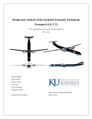
  • 1. Design and Analysis of the Jayhawk Economic Turboprop Transport (J.E.T.T) AIAA Undergraduate Team Aircraft Design Competition 2013 - 2014 Brandon Basgall Katie Constant Eleazar Lachino Adrian Lee Emily Thompson Alejandra Escalera Instructor: Dr. Ron Barrett Department of Aerospace Engineering May 10, 2014
  • 2. Aerospace Engineering Department 3 Mission Specification and Profile Provided by AIAA during the fall of 2013, the following outlines the RFP guidelines to be adhered to in the design of a new and upcoming turboprop regional airliner. The following lists the major characteristics needed to be considered for the newly designed regional turboprop aircraft: Table 2-1: Regional Turboprop Mission Specifications and Requirements (Ref. 2) Economic Mission Requirements Available Passenger Seating 75 Range 400 nautical miles Design Mission Requirements Available Passenger Seating 67 Range 1600 nautical miles Additional Considerations Necessary Mission Fuel Reserves Performance Requirements Take-off Runway Length at MTOW 4,500 feet (or shorter) Take-off Conditions (Altitude and Temp.) 7,800 feet at 85° F Cruise Speed (Mach) 0.62 – 0.68 Cruise Altitude 25,000 – 31,000 feet Fuel Consumption 65% fuel reduction from similar currently operational regional jets Cost Production Run 15 years period, 400 aircraft Total Cost Must be substantially less than currently operational regional jets Entry into Service 2022, minimum lifetime of 30 years Additional Considerations Passenger Comfort and Acceptance “Jet-like” Experience Passenger with Baggage Weight 225 lbs
  • 3. Aerospace Engineering Department 4 From the previously defined variables to be included in the design process of the new regional turboprop aircraft, the following mission profiles have been created. Figure 2-1 shows the defined economic mission under normal runway considerations of 4,500 foot runways. From this mission profile, it can be seen that the cruise conditions for this profile are noted as cruise speed between Mach 0.62 and Mach 0.68 with a cruising altitude between 25,000 and 30,000 feet. To accommodate the requested design mission of 1,600 nautical miles carrying 67 passengers, Figure 2-1 also displays the mission profile for the conventional design mission. Within this mission, the cruise speed and altitude will remain the same as seen with the economic mission, as well the same 4,500 foot runways. With the design range in mind, the design of fuel reserves will be taken into account. As designated within the RFP, the design fuel reserves will meet the FAR 25 Loiter regulations, stating the full 45 minute loiter fuel-reserve capacity. To be able to achieve the designated “high-hot” conditions outlined in the AIAA RFP, Figure 2-2 displays the adjusted mission profile. To adjust for the “high-hot” conditions, the runway length will be adjusted to 8,000 feet Figure 2-1: Design and Economic Mission Profiles of Turboprop Aircraft Figure 2-2: Design and Economic Mission Profiles for "High-Hot" Conditions
  • 4. Aerospace Engineering Department 9 Figure 4-3: Determination of Design Fix Date with Respect to Variables (Ref. 1) equation to model the distribution has been determined, it will be placed on the same plot as the first flight distribution. The vector analysis process gives engineers a tool with which they can track and predict any vector of engineering design variables at any given point in time. This point can be either in the past to analyze previous trends or in the future to see what they should prepare for. The process makes use of distribution curves by taking into account all of the desired design variables for as many aircraft, of the similar class as the one being asked for. The following is the procedure that was performed by the contestants to establish some of the critical design variables (Ref. 21 ) First a product timeline must be developed using aircraft of the same class as the one being designed. The most important dates of an aircraft’s lifecycle must be researched and gathered for use. The date of first flight of the aircraft will be plotted onto a graph and a distribution curve will be generated to fit the data. The peak of this, also the highest year for first flights of aircraft will be labeled as year zero of the aircraft’s lifecycle. The res t of the distribution will be positive or negative years with respect to the reference zero. Once this distribution has been established the design fix date for the same aircraft, it will generate another distribution curve. Once again the year at which the distribution reaches its peak will be labeled as zero. Once the graph has been observed and a good Figure 4-2: Determination of Statistical Interval Related to Rvi (Ref. 21)
  • 5. Aerospace Engineering Department 13 Empty-to-Takeoff Weight Ratio, We/Wto (~) MarketShare,(%) 1983 1984 1987 1988 1989 1990 1991 1985 1986 1992 1993 1994 1995 1996 1997 1999 1998 2000 2001 2002 2003 2004 2005 2006 2007 2008 2009 2010 2011 2012 2013 2020 0.000 0.100 0.200 0.300 0.400 0.500 0.600 0.700 0.800 0.5 0.6 0.7 PercentageofMarketShare,(%) Empty-to-Takepff Weight Ratio We/Wto (~) ATR-42 33% Fairchild 37% EMB-120 23% F-27 5% 1986 Weight Standard Deviation BAE ATP 2% Figure 5-1: STAMPED Weight Analysis
  • 6. Aerospace Engineering Department 16 6.2 Sizing Chart Analysis Utilizing the STAMPED procedure for identifying a preliminary design point, the following table is a summary of the first iteration of design. Additional analysis and multiple iterations through Class I and Class II design would ultimately lead to the final design sizing selections. Figure 6-1 is a visual representation on how the sizing values were determined. As the figure shows, by documenting the changes through time, the design point was determined. Figure 6-1: Statistical Time and Market Predictive Engineering Design (STAMPED) Sizing Chart Results In addition to the STAMPED analysis, a sizing chart was constructed following the procedure outlined in Reference 3. The results from these calculations are presented in the figure below. The results from the two methods Area, S (ft2 ) 800 Power (shp) 7530 Wing Loading (psf) 80 CLmax,clean 1.9 CLmax,landing 2.1 CLmax,TO 2.6 Table 6-1: Sizing Chart Results
  • 7. Aerospace Engineering Department 18 σ = +1 σ = -1 σ = -1 σ = +1 2020 Standard Deviation at σ = ±1 Design Point W/S Sizing Chart W/P W/S PowerLoading,(W/P)TO(lbf/hp) Take off Wing Loading (W/S)TO (lbf/ft2 ) Take off Wing Loading (W/S)TO (lbf/ft2 ) 1998 Example PowerLoading,(W/P)TO(lbf/hp) Take off Wing Loading (W/S)TO (lbf/ft2 ) PowerLoading,(W/P)TO(lbf/hp) W/P Figure 6-3: STAMPED Power and Wing Loading
  • 8. Aerospace Engineering Department 19 Class I Sizing The following sections will develop the calculations completed for a class I design analysis. This section will begin with a range of proposed configurations, followed by a down-selection to four final preliminary configuration designs. Class I design was completed on each of these four designs the results of which determined the design best fit for Class II analysis. 7.1 Preliminary Configuration Selection 7.1.1 Selection of the Aircraft Configuration For this initial stage in aircraft configuration, all possible options were considered. Driving factors of configuration selection included technical considerations such as C.G. excursion, and fuel capacity but also design goals such as range, jet-like experience for passengers, and low procurement cost. 7.1.2 Aircraft Configurations and Merit Criteria The following is a list of 12 different aircraft configurations that were considered by the team in the preliminary configuration selection process. These various designs were evaluated with respect to the requirements and objectives outlined in the RFP (Ref. 2). Table 7-1: Air Configuration Considerations 1. Box Wing 2. Vertical/Short Take Off & Landing (V/STOL) 3. Delta Wing 4. Conventional (High- Wing, Conventional Tail 5. Tail Boom, Swept Wing 6. Three Surface 7. Flying Wing 8. Tandem Wing 9. Inverted Gull Wing 10. W Wing 11. Channel Wing 12. Double Fuselage
  • 9. Aerospace Engineering Department 38 Figure 8-8: Isometric View of Engine Access Panel propeller in respect to the wing was chosen specifically for geometric clearance during low speed approach with bank angles around 5° as well as during take-off rotation (Ref. 4). The shroud will have 5 struts for support and withstand the vibration generated by the propeller and engine. Figure 8-9: Engine Removal Method The engine removal from the shroud and nacelle will require a special pulley as shown in Error! Reference source not found. Figure 8-7: Side View of Shrouded Engine
  • 10. Aerospace Engineering Department 41 on the ground. The following figures demonstrate the Prandtl-tailored δ3 wingtips which the team opted to implement. Prandtl with his research found in Über Tragflügel kleinsten induzierten Winderstandes, that the wing weight could be reduced by minimizing the moments, either creating negative bending moments to counteract the positive moments or forcing them to approach zero (Ref. 24). Figure 8-12, from Prandtl’s Über Tragflügel kleinsten induzierten Winderstandes shows the span loading concepts that were established with his research. Prandtl made the following conclusions in his document: elliptical distribution of lift is disadvantageous if trying to minimize induced drag, although the exact shape of sharp wingtips is not of high importance, sharp wingtips are advantageous when compared to squared wingtips (Ref. 24). Keeping in mind the conclusions drawn by Prandtl’s studies, the target wing span with wing tips folded could grow no larger than 79 feet (Category 2 regulations). For optimal L/D, a total wing span was set at 118 feet with an aspect ratio of 23. Figure 8-13: Boeing 737 Clean Configuration, With Prandtl-tailored δ3 Wingtips both Extended and Folded and Folding Mechanism (Ref. 24) Clearly, 118 foot wing span and aspect ratio is far outside the allotted gate spacing thus need for foldable wingtips becomes necessary to make this possible. One of the reasons why Prandtl’s concept has not been implemented in current aircraft is the weight of the hinge and actuator to fold the wingtips (Ref. 25). While the overall performance is increased, the added weight makes this design impractical for use. However, with the implement ation of Pressure Adaptive Honeycomb (PAH) weight concerns are eliminated. In this application, Pressure Adaptive Honeycomb would be used as the actuator of the wingtip and for the implementation of a δ3 hinge ensuring that the moment at the wing tip is equal to zero or insignificant (Ref. 25). While an advanced technology, PAH can be produced at a low manufacturing cost from aluminum and nylon pouches and can be integrated to conventional structures in the aerospace industry while maintaining a low part count (Ref. 24). Although the Pressure Adaptive Honeycomb can be activated by the external ambient pressure, it can be designed to actuate the
  • 11. Aerospace Engineering Department 59 Figure 9-9: Carpet Plot for Wing Loading at a Specific Range Table 9-7 : Carpet Plot Design Parameters The carpet plot here is serving as a verification of the design parameters selected. As Figure 9-9 shows, the parameters selected for the design of the J.E.T.T. can be verified and are at the optimal design point for the RFP. The following table is a summary of the design parameters collected from the above carpet plot. 0.298 0.3 0.302 0.304 0.306 0.308 0.31 74 76 78 80 82 84 86 88 SpecificRange,SR(nmi/lb) Wing Loading, W/S (lbf/ft^2) AR = 25 AR = 23 AR = 21 AR = 19 Wf = 5300 lbf Wf = 5400 lbf Wf = 5500 lbf Wf = 5600 lbf Wf = 5700 lbf Design Point Insufficient Fuel to reach 1600nmi Insufficient Fuel Space on Wing Parameter Value Specific Range, SR (nmi/lb) 0.305 Weight of Fuel, Wf (lb) 5500 Aspect Ratio, AR 23 Lift-to-Drag Ratio, L/D 21.1 Wing Loading, W/S (lbf/ft^2) 80
  • 12. Aerospace Engineering Department 60 Figure 10-1: All Systems and Subsystems of the J.E.T.T Layout of Systems and Subsystems All of the major systems were modeled in this aircraft which included:  Flight Control System  Hydraulic System  Water and Waste System  Environmental System  Electrical System  Fuel System  De-Icing System 10.1 Flight Control System The J.E.T.T. is equipped with an irreversible flight-by-light control system. An irreversible system was chosen for obvious reasons and an irreversible flight control system in an aircraft of this size would be extremely impractical and outdated. Flight-by-light was chosen in place of the more traditional fly-by-wire since the technology is available now and will only be more advanced in years to come. As it stands currently, the optics in fly-by-light systems require less space and in an aircraft as constrained for extra space as the J.E.T.T. this is important. Additionally, the 18 fiber optical cables are designed to meet all environmental, mechanical and optical requirements set for by FAR requirements (Ref. 30). For safety purposes, this system is quadruple
  • 13. Aerospace Engineering Department 64 10.6 Water and Waste System The water and waste system will be housed in the belly of the aircraft along with many of the other systems. Waste that is produced in either the front or the rear of the aircraft will be pumped into either one of the holding tanks which upon landing will be emptied. Since the entire fuselage will be pressured and heated, there is no concern that water lines may freeze in this design. 10.7 Environmental System The final system in this aircraft is the environmental system which includes the air conditioning and oxygen system; both extremely important for day to day operations and are both doubly redundant. As was mentioned previously, both the APU and RAT are capable of supplying power to the oxygen system if failure occurs elsewhere. Figure 10-8: Environmental System Shown in Green Provided Oxygen and Air Conditioning The J.E.T.T. will be equipped with an open-loop redundant cabin air conditioning and pressurization system. For passenger comfort, the cabin will be pressured at 7,500 feet (11.1 psi) and temperatures will be maintained around 70 degrees Fahrenheit.
  • 14. Aerospace Engineering Department 65 Inboard Profiles From the required RFP of a maximum amount of passengers to carry, the J.E.T.T. can accommodate 76 passengers with the addition of 2 flight attendants. To get this arrangement, the seating is organized with a 4-abreast seating throughout the full cabin. This seating arrangement allows for space at the front and the aft of the cabin for a fully functioning galley and a lavatory at the tail of the aircraft. Also, the symmetric arrangement of the seats fed into the considerations of carry-on baggage volume, aisle width and length, as well as the ease of redesigning for family variants in production. The following table details the specific cabin characteristics. Table 11-1: Internal Cabin Characteristics Inner Fuselage Diameter 102 in Number of Seats 76 Seat Pitch 20.0 in Crew Seats Attached to Aft Bulkhead Wall Seat Width 19.5 in Galley Floor Size 39 in x 26 in Aisle Width 19.0 in Lavatory Floor Size 39 in x 47 in Maximum Aisle Height 75.0 in Carry-On Baggage Volume 100.7 ft3 Aisle Width between Overhead Compartments 23.65 in Tail Cone Baggage Volume 234.7 ft3 To adhere to FAR 25 regulations, a Type III sized door will be placed in the rear of the cabin for emergency exits. The other two doors at the front of the fuselage are classified as Type IV doors to aid in loading and loading of passengers. The duel door system also allows the aircraft to be unloaded on either side of the fuselage, allowing versatility for airport handlers. Lastly, a baggage door is accounted for in the fuselage cone, where a majority of the baggage will be stowed during flight. In the following figure, the J.E.T.T.’s internal cabin is displayed with the fully arranged components. Cockpit Galley Overhead Baggage Compartments Lavatory Tail Cone Baggage Door Emergency Egress Door Figure 11-1: Internal Layout of Major Components of J.E.T.T.
  • 15. Aerospace Engineering Department 66 11.1 Accessibility The J.E.T.T. is designed for rapid “turn-around”, accessibility, maintainability and inspectability. The aircraft was laid out such that it would be possible for multiple operations to occur at once such as the loading and unloading of passengers, refueling, replenishing of potable water, cleaning of the airplane cabin, servicing lavatories as well as others. The following Figure 11-2 presents a diagram that demonstrates the potential of the airplane to satisfy customer’s needs and requirements. Figure 11-2: Terminal Servicing of J.E.T.T.
  • 16. Aerospace Engineering Department 67 Structures, Manufacturing, & Production 12.1 Structural Design Integration of the aircraft structure is an integral aspect of design and must completed carefully to avoid the addition of weight that is unnecessary and serves no added benefit to performance both in flight and in structural stability. 12.1.1 Wing Structural Design Similar to most designs, two main spars (wing box) run along the length of the wing and all sections not including the folded winglets. The winglets are supported with pressure adaptive honeycomb and require no additional internal structure. The front spar is located at 18% of the chord while the rear spar is at 72% of the chord. Wing ribs were placed where the structure required the most support and then every 19 inches. The fuel tanks were then integrated between the rib structures accordingly. Wing stiffeners were placed based upon recommendations provided in Reference 8 on general arrangement if he wing and stiffness of the aluminum skin. For the wing – fuselage integration, the wings are bolted to a fuselage carry through section near the top of the fuselage. While the wings on this aircraft are large, with an aspect ratio of 23, wing weight is not excessive therefore all internal structure as well as skins will be manufactured from composite materials. The following images depict the wing structure and design. 12.1.2 Empennage Structural Design Much like the wing, the empennage spar locations are at 18% and 72% of the chord. Rib spacing was selected to be 20 inches. Stringers again can vary and were placed appropriately to best support the structure. Also similar to the wing and which will be found throughout, the skin will be composite materials. Figure 12-1: Wing Structure and Fuselage Integration Figure 12-2: Empennage Structure and Fuselage Integration
  • 17. Aerospace Engineering Department 69 Figure 12-4: J.E.T.T. Complete Aircraft Three View
  • 18. Aerospace Engineering Department 70 12.1.4 Proposed Manufacturing Similar to current industry, the J.E.T.T. will be assembled in several outsourced locations around the world, and finally assembled in a domestic facility. From current processes used by Boeing and Spirit Aerosystems, the J.E.T.T. has several major sections of the aircraft that are composed of composite materials, thus regulated facilities that specialize in these processes would be preferred. Table 12-1 displays the J.E.T.T. broken down into the major sections defined with the main material defined, as well as the location in which the component will be produced Table 12-1: Designation of Major Components with Material Selection and Location of Production Designation Component Name Main Material Production Location 1 Cockpit Composite Outer Skin/ Aluminum Main Structure United States 2 Cabin Doors Aluminum Main Structure France 3 Fuselage Composite Outer Skin/ Aluminum Main Structure Japan 4 Engine Nacelles Boron, Kevlar Canada 5 Wing Composite Outer Skin/ Aluminum Main Structure Japan 6 Control Surfaces Composite Outer Skin/ Aluminum Main Structure Australia 7 Flexing Winglets Composite Outer Skin, Honeycomb Main Structure United States 8 Fuselage Cone Composite Outer Skin/ Aluminum Main Structure United States 9 Vertical Tail Composite Outer Skin/ Aluminum Main Structure United States 10 Horizontal Tail Composite Outer Skin/ Aluminum Main Structure Italy 11 Inside Seating Fire Retardant Materials France 12 In Flight Entertainment Electrical Components Japan 13 Cockpit Avionics Electrical Components United States In addition to displaying what main material has been selected with the location of production, Figure 12-5 displays the attachment schematic of the full J.E.T.T. once all components are received at a domestic location. 1 2 3 4 5 6 7 8 9 10 Figure 12-5: Designation of Main Components of J.E.T.T. for Production
  • 19. Aerospace Engineering Department 71 Wing Structure Middle Fuselage Structure Aft Fuselage Structure Front Fuselage Structure Vertical Tail Structure Horizontal Tail Structure Assembly of Main Aircraft Structure Engine Mounting System Integration Internal Cabin and Seating Integration Main/Nose Landing Gear Integration Final Assembly with Main Skin Components and Flexing Wing Tips Complete Assembly of J.E.T.T. Figure 12-6: Manufacturing Schematic
  • 20. Aerospace Engineering Department 73 Advanced Technologies Several advanced technologies were employed in this design to meet performance and mission objectives. A summary of each of the technologies as well as how and why they have been implemented is discussed below. 14.1 Pressure Adaptive Honeycomb (PAH) The first of the advanced technologies has been a developing technology for many years but has yet to be actively implemented. Pressure Adaptive Honeycomb (PAH) is an effective approach to minimizing structure weight but continuing to perform to the same caliber. The following section explains how PAH functions and what makes it so effective. CDP is the difference between cell pressure and ambient pressure, in which the cell pressure can be controlled by a pressure source within the aircraft. The preferred source of pressure is to have a connection between the Pressure Adaptive Honeycomb structure and the compressor stage of the engine; the PAH will not negatively affect the performance of the engine as it does not require a continuous flow of air (Ref. 27). The redundancy in the system comes from the use of CO2 cartridges if the engines fail during flight (Ref. 27). Figure 14-1: Honeycomb Grid Breakdown: Structure-Cellular Tissue-Single Cell-Cell Wall (Ref. 27) Figure 14-2: Pressure Adaptive Honeycomb Actuation and Structure Possibilities (Ref. 27) The ideal Pressure Adaptive Honeycomb would have the following characteristics as described in reference 25: easily controlled, capable of handling (-50+%) strains, stiff and strong enough to handle “real” loads, FAR 23/25 certified, all substructure within the fatigue zone labeled as “infinite life”, no continuous/dedicated power
  • 21. Aerospace Engineering Department 76 Table 14-1: Research Development, Testing and Evaluation Costs Cost Estimation and FlyOffs 14.4 Cost Estimation Following the completion of the J.E.T.T design, a detailed cost analysis was completed to estimate and predict not only the acquisition cost of this aircraft but also expenses associated with research, testing and development as well as operating costs. This analysis was completed using calculation methods as outlined in reference 10 which emphasizes the different costs of an aircraft as it relates to the different periods along an aircraft program Life Cycle as shown in Error! Not a valid bookmark self-reference.. As established in the RFP, when this design enters production it should be expected that a minimum of 400 units will be manufactured. Additionally, operational costs are largely dependent upon mission length; therefore costs will differ between the economic versus design missions. 14.4.1 Research, Development, Testing and Evaluation Costs (CRDTE) The first phases of the life cycle of an aircraft include activities which develop a new aircraft design from first concept, planning and concept exploration to certification. This phase accounts for a substantial amount of the life cycle costs and is broken down into the following sections:  Airframe Engineering and Design Cost, Caedr  Development Support and Tsting Cost, Cdstr  Flight Test Airplanes Cost, Cftar  Flight Test Operations Cost, Cftor  Test and Simulation Facilities Cost, Ctsfr  RDTE Profit, Cpror  Finance Costs, Cfinr Caed_r $ 186,367,204.51 Cdst_r $ 49,676,681.33 Cfta_r $ 245,092,067.63 Cfto_r $ 2,119,271.54 Ctsf_r $ - Cpro_r $ 48,325,522.30 Cfin_r $ 48,325,522.30 CRDTE $ 579,906,269.62 CRDTE/plane $ 193,302,089.21 Figure 14-5: Aircraft Program Life Cycle Costs (Ref. 10)
  • 22. Aerospace Engineering Department 77 A summary of the total CRDTE costs are given in . Provided in the table are two values for research and development and costs. The first is the total expected expenses for the entire program. The second value is the expected cost per airframe. It was determined that 3 test aircraft would be manufactured (for flight tests as well as static testing). The CRDTE/plane term reflects the cost of each individual aircraft. A graphical representation of these results is shown Figure 14-6. Each section represents the percentage of the total CRDTE expenses. 14.4.2 Acquisition Cost (CACQ) The importance of a reasonable acquisition cost cannot be expressed enough as it is extremely important for the continued success of an aircraft. For the calculations that were completed, as was previously stated, it is assumed that 400 units of this aircraft will be sold. Acquisition cost, in addition to factoring in program production levels, included the following costs:  Airframe Engineering and Design Cost, Caedm  Airplane Program Production Cost, Capcm  Production Flight Test Operations Cost, Cftom  Cost to Finance Manufacturing, Cfinm  Cost of Manufacturing, CMAN  Cost of Production, CPRO Caed_r $ 186,367,204.51 Cdst_r $ 49,676,681.33 Cfta_r $ 245,092,067.63 Cfto_r $ 2,119,271.54 Ctsf_r $ - Cpro_r $ 48,325,522.30 Cfin_r $ 48,325,522.30 CRDTE $ 579,906,269.62 CRDTE/plane $ 193,302,089.21 Caed_m $ 46,305,489.54 Capc_m $ 5,927,297,613.18 Cfto_m $ 9,600,000.00 Cfin_m $ 1,196,640,620.54 CMAN $ 7,179,843,723.27 CPRO $ 1,495,800,775.68 CACQ $ 8,675,644,498.95 CACQ/plane $ 21,689,111.25 Table 14-2: Acquisition Cost Summary 32.1% 8.6% 42.3% 0.4% 0.0% 8.3% 8.3% Caed_r Cdst_r Cfta_r Cfto_r Ctsf_r Cpro_r Cfin_r Figure 14-6: CRDTE Cost Summary 0.5% 68.3% 0.1% 13.8% 17.2% Caed_m Capc_m Cfto_m Cfin_m CPRO Figure 14-7: Acquisition Cost Summary