
Recomendados
Más contenido relacionado
La actualidad más candente
La actualidad más candente (20)
Destacado
Destacado (20)
Similar a Water Supply Analysis for Sand & Gravel Plant
Similar a Water Supply Analysis for Sand & Gravel Plant (20)
Último
Último (20)
Water Supply Analysis for Sand & Gravel Plant
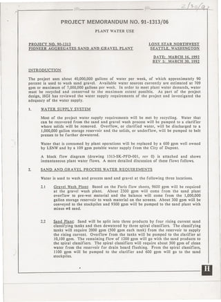
- 1. -'.~ r;._". '::::'./->0;;' )__ ?- ~~~~ __ PROJECT MEMORANDUM NO. 91-1313/06 PLANT WATER USE PROJECT NO. 90-1313 LONE STAR NORTHWEST PIONEER AGGREGATES SAND AND GRAVEL PLANT SEATTLE, WASHINGTON DATE: MARCH 16, 1992 REV I: MARCH 30, 1992 INTRODUCTION The project uses about 40,000,000 gallons of water per week, of which approximately 90 percent is used to wash sand gravel. Available water sources currently are estimated at 709 gpm or maximum of 7,000,000 gallons per week. In order to meet plant water demands, water must be recycled and conserved to the maximum extent possible. As part of the project design, HGI has reviewed the water supply requirements of the project and investigated the adequacy of the water supply. 1. WATER SUPPLY SYSTEM Most of the project water supply requirements will be met by recycling. Water that can be recovered from the sand and gravel wash process will be pumped to a clarifier where solids will be removed. Overflow, or clarified water, will be discharged to a 1,000,000 gallon storage reservoir and. the solids, or underflow, will be pumped to belt presses to be further dewatered. I Water that is consumed by plant operations will be replaced by a 600 gpm well owned by LSNW and by a 109 gpm potable water supply from the City of Dupont. A block flow diagram (drawing 1313-SK-PFD-00I, rev 0) is attached and shows instantaneous plant water flows. A more detailed discussion of these flows follows. 2. SAND AND GRAVEL PROCESS WATER REQUIREMENTS Wa ter is used to wash and process sand and gravel at the following three locations. 2.1 Gravel Wash Plant: Based on the Faris flow sheets, 9600 gpm will be required at the gravel wash plant. About 2300 gpm will come from the sand plant overflow to pre-wet material and the balance will come from the 1,000,000 gallon storage reservoir to wash material on the screens. About 300 gpm will be conveyed to the stockpiles and 9300 gpm will be pumped to the sand plant with minus #8 sand. 2.2 Sand Plant: Sand will be split into three products by four rising current sand classifying tanks and then dewatered by three spiral classifiers. The classifying tanks will require 2000 gpm (500 gpm each tank) from the reservoir to supply the rising current. Overflow from the tanks will be pumped to the clarifier at 10,100 gpm. The remaining flow of 1200 gpm will go with the sand products to the spiral classifiers. The spiral classifiers will require about 500 gprn of clean water from the reservoir for drain board flushing. From the spiral classifiers, 1100 gpm will be pumped to the clarifier and 600 gpm will go to the sand stockpiles. ~-----------------------II
- 2. ,~ < '------------------------~ 2.3 Load Out Tower: Course material aggregates (#4 to 1.5 inches) will be rinsed at the loadout tower before leaving the site. Rinse water requirements will be 2400 gprn at 2400 tph. About 200 gpm will leave with the product and the rest will be returned either to the clarifier or to a loader sump to be recirculated. Make-up water will come from the reservoir. The current plan is to recirculate the rinse water until an undesirable amount of fines accumulate, at which time the water will be pumped to the clarifier. Rinse water may need to be recirculated for up to 60 hours if the clarifier operates only when the processing plant operates. This mode of operation may need to be adjusted if rinse water becomes to dirty to be recirculated. 3. OTHER WATER USES Water will be required at several other locations in the plant. Estimated instantaneous water use at these locations is listed below: Location Demand GPM 1. Office and shops 25 2. Asphalt and concrete plant 160 3. Clean-up, dust suppression, evaporation 175 4. Irrigation 25 4. WATER LOSSES Table 1 lists the estimated system water losses. The information in the table was obtained from Faris flow sheets, a Faris letter dated January 24, 1991, LSNW calculations dated November 22, 1991 and HGI estimates. These .estimates are preliminary and will be further defined as equipment is selected and the project scope is finalized. TABLE 1: PLANT WATER LOSSES
- 3. ~'----------------------- :,~ -------------------------, 5. WATER SUPPLY ANALYSIS To determine the adequacy of the water supply system, HGI simulated hourly water use and supply for a typical week of plant operation. The following cases of water use and water recycling were simulated. Each case was simulated for water make-up capacities that ranged from 500 gpm to 1000 gpm. Case 1: No water recovery from the gravel and sand piles. Case 2: 50 percent water recovery from the gravel piles and 60 percent recovery from the sand piles. 6. au ALIFICA TIONS AND ASSUMPTIONS 6.1 Water losses were based on Table I values. 6.2 The stockpile recovery percentages are based on Faris Associates' past experiences. 6.3 Water loss in the sludge assumes 60 percent solids from the belt press. 6.4 Make-up water supply is available on a continuous basis. 7. SUMMARY AND CONCLUSIONS The results of the water supply analysis are shown in detail on the attached tables and graphs. Case 1: At a continuous water make-up flow of 709 gpm, the reservoir never refills during the 5 days the plant operates and the minimum reservoir tank volume is 300,000 gallons. A minimum continuous make-up flow of 670 gpm is required to keep at least 100,000 gallons in the reservoir. Case 2: At a continuous water make-up flow of 709 gpm, the reservoir refills at the end of each day and the minimum reservoir tank volume is 700,000 gallons. A minimum continuous make-up flow of 430 gpm is required to keep at least 100,000 gallons in the reservoir. The analysis indicates that the make-up water capacity of 709 gpm should be adequate if the water loss assumptions used are correct. In any case, an additional make-up water source of 200 gpm from either a shallow well or from the City of Dupont should be enough to cover any contingency. Report Prepared By: HARRIS GROUP INC. CRO/gbm (S~ Project Manager 91-13131313pm06 j cc: Ron Summers, LSNW JCL, File 1313.507 91-I313/1313PM06, Rev I - 3- 30 Mar 1992 -- -- --- ---------- ---- --- ~- .~-- 11I