1. Seismic
Performance
and
Design
of
Embedded
Steel
Column
Base
Connec8ons
Emmanuel
Flores1,
David
Grilli2,
and
Amit
Kanvinde2,
Ph.
D.
1Department
of
Civil
and
Environmental
Engineering,
University
of
California,
Berkeley,
94720
2Department
of
Civil
and
Environmental
Engineering,
University
of
California,
Davis,
95616
Column
base
connecJons
are
very
important
structural
interfaces
because
this
is
where
load
is
transferred
from
the
enJre
structure
to
the
foundaJon.
It
is
common
for
embedded
columns
to
be
the
preferred
alternaJve
to
restrain
column
bases
of
mid-‐to-‐high
rise
buildings
in
highly
seismic
regions
due
to
its
ability
to
beNer
resist
moment
and
shear.
Despite
the
widespread
use
of
embedded
columns,
there
is
very
liNle
experimental
data
and
no
true
design
guidelines
on
this
type
of
connecJon.
What
this
invesJgaJon
will
do
is
develop
a
fundamental
understanding
of
the
force
transfer
mechanisms
and
demonstrate
strength,
sJffness,
ducJlity,
and
damage
states
that
occur
in
embedded
columns.
To
do
this,
five
realisJcally-‐sized
embedded
columns
will
be
taken
to
a
strong
reacJon
floor
to
be
subjected
to
various
combinaJons
of
axial
compression
or
tension
with
cyclic
lateral
loading.
Data
from
these
tests
will
be
recorded
as
lateral
force-‐displacement
hystereJc
curves,
stress
distribuJons
over
the
embedded
part
of
the
columns,
and
observed
failure
modes.
Abstract
• Use
calibraJon
plots
to
convert
future
voltage
data
into
values
of
distance
and
strain.
• Determine
strength,
sJffness,
and
damage
states
• Develop
equaJons
for
strength
and
update
building
codes,
standards,
and
specificaJons
Next
Steps
A
special
thanks
to:
• Professor
Amit
Kanvinde
and
David
Grilli
• Cal
NERDS
• UC
LEADS
Acknowledgements
Background
• Column
base
connecJons
are
some
of
the
most
crucial
connecJons
in
a
steel
frame
since
they
transfer
forces
from
the
enJre
structure
to
the
foundaJon.
• Earthquakes
are
known
to
produce
large
moment
and
shear
forces
in
a
building
which
can
place
a
risk
on
the
safety
of
people
and
the
building
itself.
• The
two
most
frequent
types
of
connecJon
used
in
pracJce
are
the
exposed
column
base
connecJon
and
the
embedded
column
base
connecJon.
• For
the
steel
frame,
the
embedded
column
base
connecJon
is
the
most
effecJve
type
of
base
connecJon
for
buildings
in
earthquake
prone
regions
because
of
their
ability
to
resist
moment
and
shear.
Figure
1.
Figure
2.
Figure
1
is
an
example
of
an
embedded
connecJon
while
Figure
2
is
an
example
of
an
exposed
connecJon.
These
are
the
two
most
commonly
used
connecJons
for
steel
frames.
Methods
For
this
experiment,
5
steel
columns
will
be
used
with
varying
heights
of
12
to
14
feet.
Each
column
will
be
embedded
into
a
block
of
concrete.
The
steel
column
specimens
will
be
tested
on
a
strong
reacJon
floor
where
a
hydraulic
actuator,
capable
of
producing
200
kips
of
force,
will
generate
cyclic
lateral
forces.
Along
with
being
subjected
to
a
lateral
force,
the
specimens
will
also
be
subjected
to
either
axial
tension
(Figure
3.)
or
compression
(Figure
4.)
Figure
3.
Figure
4.
Each
specimen
will
be
a
different
combinaJon
of
lateral
force
and
axial
force
as
shown
in
Table
1
below.
Table
1.
The
data
that
will
be
collected
from
these
specimens
will
be
displacement
along
the
length
of
the
column
and
stress
values
in
the
embedded
porJon
of
the
column.
Linear
potenJometers
and
string
potenJometers
will
be
used
to
measure
displacement
while
strain
gauges
will
be
measuring
strain.
The
types
of
instruments
and
their
placement
on
the
specimen
are
shown
below
in
Figures
5
and
6.
Figure
5.
Figure
6.
Top
View
of
Column
Specimen
Side
View
of
Embedded
PorJon
of
Column
Test
#
Column
Size
Loading
(kips)
Embedment
(in.)
1
W14x370
Axial
0
+
Lat.
40
2
W14x370
Axial
500
(C)
+
Lat.
40
3
W14x370
Axial
500
(T)
+
Lat.
40
4
W14x370
Axial
500
(C)
+
Lat.
20
5
W18x311
Axial
500
(T)
+
Lat.
20
Preliminary
Results
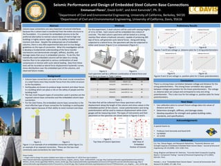
Figure
7.
Figure
8.
Figures
7
and
8
are
voltage
vs.
distance
plots
for
2
string
potenJometers.
Figure
9.
Figure
10.
Figures
9
and
10
are
voltage
vs.
posiJon
plots
for
2
linear
potenJometers.
y
=
0.0954x
+
0.0401
0
0.5
1
1.5
2
2.5
3
3.5
4
4.5
5
0
10
20
30
40
50
60
Voltage
(V)
Distance
(in.)
Calibra8on
Plot
for
SP1
y
=
0.0952x
+
0.0505
0
0.5
1
1.5
2
2.5
3
3.5
4
4.5
5
0
10
20
30
40
50
60
Voltage
(V)
Distance
(in.)
Calibra8on
Plot
for
SP2
y
=
3.2471x
-‐
0.8103
0
1
2
3
4
5
6
0
0.2
0.4
0.6
0.8
1
1.2
1.4
1.6
1.8
2
Voltage
(V)
Posi8on
(in.)
Calibra8on
Plot
for
LP1
y
=
3.3119x
-‐
1.0336
0
1
2
3
4
5
6
0
0.2
0.4
0.6
0.8
1
1.2
1.4
1.6
1.8
2
Voltage
(V)
Posi8on
(in.)
Calibra8on
Plot
for
LP2
Conclusions
There
is
a
strong
linear
correlaJon
between
voltage
and
distance
for
the
string
potenJometers.
This
strong
linear
correlaJon
also
appears
between
voltage
and
posiJon
for
the
linear
potenJometers.
The
voltage
vs.
distance
plots
are
unique
and
correspond
to
only
one
string
potenJometer.
This
is
also
true
for
the
voltage
vs.
posiJon
plots
for
linear
potenJometers.
Photo
Credits:
• Images
used
to
design
the
poster
(sidebar)
were
taken
on
(September
27,
2013)
from
top
to
boNom:
hNp://upload.wikimedia.org/wikipedia/commons/1/1b/Los_Angeles_Library_Tower_%28small%29_crop.jpg,
hNp://upload.wikimedia.org/wikipedia/en/thumb/5/51/
Wilshire_Grand_Center.jpg/220px-‐Wilshire_Grand_Center.jpg
,hNp://upload.wikimedia.org/wikipedia/commons/c/c9/Taipei101.portrait.altonthompson.jpg,
hNp://
upload.wikimedia.org/wikipedia/en/b/bc/Transamerica_Pyramid1.jpg,
hNp://upload.wikimedia.org/wikipedia/commons/7/70/Downtown_Los_Angeles_-‐_Aon_Center.jpg
References
Cui,
Yao,
Takuya
Nagae,
and
Masayoshi
Nakashima.
“HystereJc
Behavior
and
Strength
Capacity
of
Shallowly
Embedded
Steel
Column
Bases.”
Journal
of
Structural
Engineering
135.10
(2009).
1231-‐1238.
Print.
Gong,
Bingnian
and
Bahram
M.
Shahrooz.
“Concrete-‐Steel
Composite
Coupling
Beams
I:
Component
TesJng.”
Journal
of
Structural
Engineering
127.6
(2001).
625-‐631.
Print.
Pertold,
J.,
et
al.
“Embedded
Steel
Column
Bases.”
Journal
of
Construc3on
Steel
Research
56
(2000).
271-‐286.
Print.