NABA 2014 - Design & laser cut
•
11 recomendaciones•11,583 vistas

why and how to use a laser cut. Projects, ideas, suggestions and tips.

Recomendados
Recomendados
Más contenido relacionado
La actualidad más candente
La actualidad más candente (20)
Similar a NABA 2014 - Design & laser cut
Similar a NABA 2014 - Design & laser cut (20)
Más de Enrico Bassi
Último
Último (20)
NABA 2014 - Design & laser cut
- 1. LLAASSEERR CCUUTTTTIINNGG IINNTTRROO,, EEXXAAMMPPLLEESS AANNDD AAPPPPLLIICCAATTIIOONNSS
- 2. LASER The laser cuts by concentrating a high level of energy in a small spot, melting, burning or vaporizing the material which consequently is being blown away by a gas jet, leaving a very high quality cut.
- 3. THE CUT The laser makes a very precise cut, usually perpendicular to the bed, with a thickness varying from 0,1 to 0,5 mm. The average is considered 0,2 mm In some particular cases, for example glass, it could have no thickness since it cuts through thermal shock. The characteristics depend on the machine being used. http://scottcampbellstudio.com/
- 4. THE CUT – make a frames
- 5. DESIGN THE NOTCHES Design notches on the borders of the pieces helps to obtain a more resistant piece. Usually the lenght is at least 3 times the thickness of the material
- 6. AN EXAMPLE: THE BOX The box is the first example of a project to laser cut. The easiest shape is the cross. If the box would be cut following these lines it would be impossible to mount due to the thicknesses, that in this case are not considered.
- 7. AN EXAMPLE: THE BOX Moving on to designing the joints of the pieces, you can see that once the pieces are mounted, the total lenght is less than what would be expected.
- 8. STEP 1: mark middle points
- 9. STEP 2: basic module
- 10. STEP 3: copy it up to the middle point
- 11. STEP 4: mirror it and fix the extra lines
- 12. STEP 5: copy or mirror it where there is the same base line
- 13. STEP 6: mirror around a 45° the basic module
- 14. STEP 7: follow the steps from 3 to 6 again
- 15. STEP 8: copy the basic module to the next border
- 16. STEP 9: mirror it and draw the last side
- 17. STEP 10: delete everything not needed and cut the extra lines
- 18. STEP 11: optimize the space and delete the duplicate lines
- 20. ASSEMBLING The easiest one is linear. It has no interference nor curves. It can be regular, or irregular. http://blog.makezine.com/2012 /04/13/cnc-panel-joinery-notebook/
- 21. ASSEMBLING Usually you try to create perfectly specular pieces to facilitate the assembly. If that isn't possible, it's better to accentuate the differences to reduce the risk of mounting them incorrectly. http://blog.makezine.com/2012/04/ 13/cnc-panel-joinery-notebook/
- 22. ASSEMBLING In this case it's better to make the joints asymmetrical, to mount the surfaces in the right order.
- 23. ASSEMBLING The linear joint can be placed even in the centre of the surface. http://blog.makezine.com/2012/04/ 13/cnc-panel-joinery-notebook/
- 24. ASSEMBLING The geometry of the linear joints can be mixed with the use of screws to create resistant and reversible joints. http://blog.makezine.com/2012/04/ 13/cnc-panel-joinery-notebook/
- 25. ASSEMBLING The joints with screws can be used even on the edges. http://blog.makezine.com/2012/04/ 13/cnc-panel-joinery-notebook/
- 26. ASSEMBLING The joints might not be in a 90° angle, or with perpendicular walls. http://blog.makezine.com/2012/04/ 13/cnc-panel-joinery-notebook/
- 27. ASSEMBLING In flat joints you can even use different geometries. Ift he goal is to create a joint that is resistant without the use of glue you can use the puzzle shape. If you want to facilitate the gluing and centering of the pieces, you can use the comb shape. http://blog.makezine.com/2012/04/ 13/cnc-panel-joinery-notebook/
- 28. SNAPFIT Using the elasticity of the material you can even create snapfits. Usually they are very delicate elements. http://blog.makezine.com/2012/04/ 13/cnc-panel-joinery-notebook/
- 29. KEYS Other kind of joints use the rotation or sliding of an element. http://blog.makezine.com/2012/04/ 13/cnc-panel-joinery-notebook/
- 30. COMPLEX JOINTS Combining what we've seen above you can create highly articulate joints. http://blog.makezine.com/2012/04/ 13/cnc-panel-joinery-notebook/
- 31. JOINTS IN 2.5D Gluing different layers it is even possible to use the tipical milling joints. http://www.flexiblestream.org/Digit al-Wood-J oints-001.php
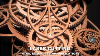
- 33. THE CUT - gears
- 38. THE CUT - hinges
- 39. THE CUT - mechanism
- 41. THE INLAY Using the precision of the cut you can wedge in pieces of different materials (different tipes of wood, different coloured plexiglass, etc.) to reproduce the effect of inlay.
- 42. THE DOTTED LINES PARTIAL CUT Through the settings of the machine, it's possible to create dotted lines, by creating cuts that are interrupted. In the file they appear as continous lines, but with an assigned frequency of turning on and off the laser. This is very useful for paper, when you want to create folding lines.
- 46. MATERIAL Easily cut: ● plexiglass (max 5mm) ● Wood/plywood (max 6mm) ● Cardboard, paper, etc. ● Rubber, leather, fabrics, etc. Not easily cut: ● PC ● PVC ● Glass ● Metal ● Thich materials (including foams)
- 47. THE ENGRAVE By regulating the potency and the focus it is possible to incise lines, which don't cut through the material, onto the surface. The thickness and the depth of the incisions depends on the parameters of the machine, and the material. It's very useful even when wanting to number pieces which eventually has to be mounted together. Generally it's a good idea to make a test, to check the result. http://blog.ponoko.com/2010/07/14/laser-engraving- and-processing/
- 48. THE ENGRAVING It is possible to chose directly from the file closed paths within which you want to assing a filling. Based on the power it is possible to change the depth of the engraving.
- 49. THE IMAGES Using an analog principle, you can assign various power related to the brightness of the pixels in an immage. If the power is low you obtain a “grayscale print” of the immage. If the power is high you obtain an effect similar to the bas-releif.
- 50. Z-BUFFER IMAGES Some particular images store the depth values in a 3D image, associating them to the brightness of the pixels. If you laser cut it the result is very similar to a bas-relief.
- 51. MATERIALS You can engrave: ● Plexi glass (max 5mm) ● Wood/plywood (max 6mm) ● Cardboard, paper, etc. ● Rubber, leather, fabrics, etc. ● Anodized metals ● Varnished metals ● Glass ● Stone ● Ceramics
- 53. FOR WOOD AND PLEXI These are 2.5 or 3 axis machines. Usually the laser source is CO2 based The laser bounces on several mirrors before focusing on the piece. http://www.vectorealism.com/
- 54. FOR METALS The principle is very similar to the last one, but the power is higher. Sometimes it uses a different sources of lasers instead of mirrors. http://www.lasermio.com/
- 55. GALVANIC LASER Instead of cartesian axis, it uses mirrors The working area is usually smaller, and related to the lens used. Also the quality is related to the lens. On the other hand it's much faster than the traditional 3 axis laser http://www.youtube.com/watch?v=ybCN5QkppLw
- 56. MORE THAN 3 AXIS LASER To work on more complex shapes lasers can have more than 3 axis Obviously it's a more expencive and complex machine.
- 57. EXAMPLES
- 58. PROFILES In its' easiest form, the laser cuts profiles in flat sheets. These profiles can then be mounted together in a permanent or temporary way.
- 59. PROFILES 2 The molded pieces can be curved into 3D objects. http://besttopdesign.com/lighting/levent-romme% E2%80%99s-in-bklyn-designs-show- with-elegant-laser-cut-paper-lamps/
- 60. FASHION Laser cutting fabric is something fairly common and easily made.
- 61. PERPENDICULAR SECTIONS One of the easiest ways to describe a complex geometry is to wedge perpendicular sections together.
- 62. RADIAL SECTIONS As an alternative you can use a radial disposition, especially for a revolving solid.
- 63. MULTILAYER Another way to create 3D objects is multilayering. There are even some free softwares that slice the objects to work in this way. http://www.123dapp.com/
- 64. MULTILAYER 2 If the layers are very thin the result is a practially continous piece. http://www.laser-stanzungen.de/
- 65. DIFFERENT DIRECTION It's obviously possible to combine section with different directions together, to make a single object
- 66. WEDGING 1 The various elements can be wedged together and assembled to create for example a box. There are online tools made to automatically design simple boxes. http://boxmaker.rahulbotics.com/
- 67. FLEXIBLE LASER CUTS Using paritcular patterns you can obtain very flexible materials. This does however create a very fragile object. http://www.flickr.com/photos/maindinte raction/7655393032/sizes/l/in/photostr eam/
- 68. WEDGING 2 Increasing the level of complexity you can create very advanced objects. The easiest way to wedge pieces is at a 90° angle, but you can join pieces even in other angles.
- 69. WEDGING 3 The pieces can be jointed or static. It's very simple to create precise cuts and stable wedgings. This highly facilitates the realization of mobile parts. http://www.instructables.com/id/Laser- Cut-Front-End-Loader-Toy/
- 70. FOLDABLE PIECES If properly designed, you can even achieve foldable parts. It is, however, difficult to create them using only a laser cutter. http://www.core77designawards.com/ 2012/recipients/laser-cut-folding-ukulele- kit/
- 71. MECHANISMS 2 Combining the various elements, the final result can be a highly complex object. http://www.bustedbricks.com/mar ble-machine-kit-1-146-p.asp
- 72. MAIN SOURCES http://blog.ponoko.com/ http://www.ve ctorealism.com/ http://grabcad.com/challenge s /the -e vd-make -your-lase r-cut-toy-conte s t/ http://cncking.com/category/toys