SlideShare una empresa de Scribd logo
1 de 4
Descargar para leer sin conexión
IOSR Journal of Mechanical and Civil Engineering (IOSR-JMCE)
e-ISSN: 2278-1684,p-ISSN: 2320-334X, Volume 12, Issue 3 Ver. III (May. - Jun. 2015), PP 72-75
www.iosrjournals.org
DOI: 10.9790/1684-12337275 www.iosrjournals.org 72 | Page
Design Analysis & Simulation Based Techno-Feasibility Testing
Of Centre Mounted Suspension System
Neeraj Dadhwal1
, BalRam Bhardwaj2
, Suresh Bhardwaj 3
3,1
Mechanical Department, DITMR College, MDU University, Rohtak, Haryana, India,
2
Maclec Technical Project Laboratory, New Delhi, India
Abstract : Suspension systems can be described as the shock absorbing system installed along with
the wheels in automobiles with the purpose of maintaining maximum possible required interaction
between wheel and the surface. Apart from it, the suspension systems made vehicle driving experience
luxurious, comfortable and pleasurable. Suspension systems also play vital role in maintaining
vehicle balancing by keeping the centre of gravity in the centre, so that the overall gravitational pull
does not interrupt in vehicle balancing during turning on steep corners, course of rough terrain and
also during acceleration. At the time of vehicle acceleration, it is very much important to break static
inertia of vehicle in such a manner so that the vehicle easily maintains kinetic inertia along with
overall balancing. There are numerous suspension systems available which are still in use in order to
maintain vehicle balance and comfort. The endeavour of this proposed research is to introduce a new
class of suspension system in order to rid of existing risk factors associated with conventional
suspension system. In order to fulfil desired goal, 3D analysis of proposed system will be done along
with stress analysis to find out suitable composite material for its fabrication and its installation
manual.
Keywords:–Acceleration, balancing, suspension, terrain, vehicle, etc.
I. Introduction
Automotive Suspension is the type of system which associates vehicle tires, pressurised tire
air, Specific springs, hydraulic/air based shock absorbers and distinct linkages that connects a vehicle to
its wheels through axial and allows required relative motion between the two. As far as its importance is
concerned, the suspension systems perform two distinguished services by contributing to the vehicle's over all
balancing in every terrain and assuring good active safety and driving pleasure through keeping vehicle
occupants comfortable and a ride quality. Suspensions also maintain reasonably well isolated inner environment
for vehicle from road noise, bumps, and vibrations by acting as an active shock absorber.
Conventional suspension systems are equipped with all above said features but lagging behind in some
distinctive features such as providing balance in all terrains, maintain centre of gravity exactly during
acceleration as well as distributing shock during obstacle crossing equally towards centre of the chassis. The
proposed centre mounted suspension system is being evolved to cater all such needs in the development of all
terrain vehicles. Centre mounted suspension system is beam based system which are directly attached to the
central chassis of vehicle to give way to transfer the entire jerk towards centre. The system is simplest enough to
install in any type of vehicle.
II. Literature Review
In generally, there are three main types of suspension system which are passive type, semi-active type
and active type of suspension system and widely investigated by many researchers with different techniques and
algorithms as well. The passive suspension system in vehicles showed unsatisfactory performances in vehicle
stability as compared with semi-active and active suspension system because of lack of situation specific
components. The working behaviour of passive automotive suspension systems is determined through the
selection of the spring stiffness and the coefficient of jerk or dumper. The fixed type of damper and spring
component of passive suspension system has not well enough for energy absorption to take the load or road
obstacles acted over the vehicle system.
The semi-active type suspension system uses a distinct damper and other variable dissipation
component in the automotive suspension and the example of a variable dissipater is a double tube viscous
damper in which the damping coefficient can be varied by changing the diameter of the bore in a piston. Next
example is of semi-active dissipater, which is a magneto rheological (MR) damper and used MR fluid system
where MR fluids are materials who respond to an applied magnetic field with a change in rheological behaviour.
Design Analysis & Simulation Based Techno-Feasibility Testing Of Centre…
DOI: 10.9790/1684-12337275 www.iosrjournals.org 73 | Page
The Semi-active type suspension systems have been investigated in various literatures in place to achieve low
energy utilization and as a good performance as full-active suspension systems because semi-active system can
adjust the damping and thus improve either ride comfort or ride safety compared to the passive system.
The Active type suspensions are equipped with electronic control systems which controlling operation
of the suspension elements during real time use due to which they have not a limited performance like passive
suspensions and create a new advancement in eliminating the drawbacks of the design compromise present in
passive suspensions. The implementation of Active suspension system reduces car body acceleration by
allowing the suspension to `absorb' wheel accelerations using an actuator. Recent works and researches on
active suspensions have been carried out by numerous researchers to improve the stability and ride handling
performance of the vehicle.
The all above mention suspension system categories, the proposed centre mounted suspension system
remain most advanced, distinct but remain in the category of passive suspension systems because it lack any
electrical or mechatronical equipment and components, despite of all these laggings the centre mounted
suspension system contains all guts to maintain vehicle jerks even during rush driving due to its unique
designing and extra ordinarily simple formulation.
.
III. Principle
The centre mounted suspension system is based upon two distinct phenomenon i.e. leverage and spring
tension. The leverage remain Mechanical advantage which is measures of the force amplification achieved by
using a tool, mechanical device or machine system and ideally during leverage the device preserves the input
power and simply transfer this off against movement to obtain a desired amplification in the output force in
another distinct point. This leverage advantage is present in the main shaft where the wheel is mounted and
through which the entire suspension system attached to the chassis.
The Spring, in this case act as a pivot which transfer the torque from wheel base to the chassis and
during this transformation, maximum displacement is disappeared as accordance to spring constant.
Fig: Centre Mounted suspension system Installation arrangement 3D.
IV. Methodology
The above said features are embedded with the very initial design of suspension system, but these goals
are generally at odds and depending upon the well tuning of suspension with the vehicle. The tuning of
suspension with vehicle involves finding the right combination of strength, shock absorbing capacity and type of
vehicle. It is utmost important for the suspension system to maintain maximum possible contact area between
the road and the wheel because all the road or ground forces acting on the vehicle do so through the contact
patches of the tires which finally provides required friction to facilitate breaching the static inertia of the vehicle
and maintaining the kinetic inertia . The suspensions also act as a protector and protects the vehicle itself and
any cargo or luggage from damage and wear by absorbing the shock generated due to rough driving or rough
terrain.
In order to find of possibility to install the proposed suspension system into ATV, 3D modelling using
SOLIDWORKS has been done and according to the working a small prototype is being fabricated.
Design Analysis & Simulation Based Techno-Feasibility Testing Of Centre…
DOI: 10.9790/1684-12337275 www.iosrjournals.org 74 | Page
Fig: Implementation of Centre Mounted Suspension system.
V. Mathematical Calculations
Fabrication As per the principle of leverage, it is being proved that using leaver, torque could be
transferred from one point to another.
Fig: Graphical Presentation of Leverage system.
If a and b are the leaver from the fulcrum to points A & B and if force FA implanted to A is the
incidental force and FB is received & B is the output, the ratio of the velocities of points A and B is given
by a/b, so the ratio of the outlet force to the inlet force or mechanical advantage generated due to leverage, is
can be given by
VI. Results & Discussion
Fig: Stress Analysis of Leaver joints and leaver rod using ANSYS.
Design Analysis & Simulation Based Techno-Feasibility Testing Of Centre…
DOI: 10.9790/1684-12337275 www.iosrjournals.org 75 | Page
As per the Stress analysis and torque transmission analysis, it is being proved that the centre mounted
suspension system provides major advantages during sharp turns and bumpy rides where other conventional
suspension system get failed.
In comparison with existing suspension systems, the centre mounted suspension system is maintaining
its uniqueness throughout, weather it is design or mode of installation. Unlike conventional suspension systems,
the proposed system is directly attached with the centre of vehicle chassis and due to which the overall jerk,
displacement and vibrations generated due to terrain and driving condition, the vehicle never get miss-balanced
because of the distinctive specified design of the proposed suspension system.
The proposed system is based upon leverage phenomenon, in which the shaft which attached to the
centre, act as a leaver and the suspension spring, which installed at predefined and calculated place in between
the joint and the wheel base is act as a PIVOT which allows to transfer all the jerk and vibration direct to the
centre while absorbing most of the jerk in between.
VII. Conclusion
There is tremendous scope to implement centre mounted suspension system in four wheelers and heavy
loading vehicles in order to make ride more economic, luxurious, safe and advantageous. As far as the future
scope is concerned, the system is capable enough to tackle all the existing problems related to conventional
suspension systems in a single go.
References
Journal Papers:
[1]. B. Chen, X. Liu, S. Tong, and C. Lin, “Observer-based stabilization of T–S fuzzy systems with input delay,” IEEE Trans. Fuzzy
Syst., vol. 16, no. 3, pp. 652–663, Jun. 2008.
[2]. Vehicle Suspension Systems Control: A Review Ayman A. Aly, and Farhan A. Salem, INTERNATIONAL JOURNAL OF
CONTROL, AUTOMATION AND SYSTEMS VOL.2 NO.2 July 2013 ISSN 2165-8277 (Print) ISSN 2165-8285 (Online)
http://www.researchpub.org/journal/jac/jac.html.
Books:
[3]. J. J. Uicker, G. R. Pennock, and J. E. Shigley, 2003, Theory of Machines and Mechanisms, Oxford University Press, New York
Theses:
[4]. Robust Control Design for Vehicle Active Suspension Systems with Uncertainty, Hongyi Li School of Creative Technologies
University of Portsmouth A thesis submitted for the degree of Doctor of Philosophy June 2012.

Más contenido relacionado

La actualidad más candente

Modelling simulation and control of an active suspension system
Modelling  simulation and control of an active suspension systemModelling  simulation and control of an active suspension system
Modelling simulation and control of an active suspension systemIAEME Publication
 
INVESTIGATION OF SELF-POWERED ACTIVE SUSPENSION CONTROL
INVESTIGATION OF SELF-POWERED ACTIVE SUSPENSION CONTROLINVESTIGATION OF SELF-POWERED ACTIVE SUSPENSION CONTROL
INVESTIGATION OF SELF-POWERED ACTIVE SUSPENSION CONTROLMalshana Tilakaratne
 
Modeling & Simulation of Shock-Absorber Test Rig
Modeling & Simulation of Shock-Absorber Test RigModeling & Simulation of Shock-Absorber Test Rig
Modeling & Simulation of Shock-Absorber Test RigAnkit Kumar Dixit
 
IRJET-Springless Type Magnetic Suspension
IRJET-Springless Type Magnetic SuspensionIRJET-Springless Type Magnetic Suspension
IRJET-Springless Type Magnetic SuspensionIRJET Journal
 
Electromagnetic Suspension
Electromagnetic SuspensionElectromagnetic Suspension
Electromagnetic SuspensionMahaveer Kakade
 
A presentation on suspension using simulink
A presentation on suspension using simulinkA presentation on suspension using simulink
A presentation on suspension using simulinkIMTH0
 
Electromagnetic suspension system
Electromagnetic suspension systemElectromagnetic suspension system
Electromagnetic suspension systemdrshifahn
 
IRJET- Dynamic Analysis of the Front and Rear Suspension System of an All...
IRJET-  	  Dynamic Analysis of the Front and Rear Suspension System of an All...IRJET-  	  Dynamic Analysis of the Front and Rear Suspension System of an All...
IRJET- Dynamic Analysis of the Front and Rear Suspension System of an All...IRJET Journal
 
design and analysis of an All Terrain Vehicle
design and analysis of an All Terrain Vehicledesign and analysis of an All Terrain Vehicle
design and analysis of an All Terrain VehicleNikhil kadasi
 
Fatigue or Durability Analysis of Steering Knuckle
Fatigue or Durability Analysis of Steering KnuckleFatigue or Durability Analysis of Steering Knuckle
Fatigue or Durability Analysis of Steering Knuckleijsrd.com
 
NMSU_Design_Report_2016
NMSU_Design_Report_2016NMSU_Design_Report_2016
NMSU_Design_Report_2016Arthur Cox
 

La actualidad más candente (16)

Modelling simulation and control of an active suspension system
Modelling  simulation and control of an active suspension systemModelling  simulation and control of an active suspension system
Modelling simulation and control of an active suspension system
 
INVESTIGATION OF SELF-POWERED ACTIVE SUSPENSION CONTROL
INVESTIGATION OF SELF-POWERED ACTIVE SUSPENSION CONTROLINVESTIGATION OF SELF-POWERED ACTIVE SUSPENSION CONTROL
INVESTIGATION OF SELF-POWERED ACTIVE SUSPENSION CONTROL
 
Modeling & Simulation of Shock-Absorber Test Rig
Modeling & Simulation of Shock-Absorber Test RigModeling & Simulation of Shock-Absorber Test Rig
Modeling & Simulation of Shock-Absorber Test Rig
 
IRJET-Springless Type Magnetic Suspension
IRJET-Springless Type Magnetic SuspensionIRJET-Springless Type Magnetic Suspension
IRJET-Springless Type Magnetic Suspension
 
Active suspension
Active suspensionActive suspension
Active suspension
 
Published Paper
Published PaperPublished Paper
Published Paper
 
Electromagnetic Suspension
Electromagnetic SuspensionElectromagnetic Suspension
Electromagnetic Suspension
 
A presentation on suspension using simulink
A presentation on suspension using simulinkA presentation on suspension using simulink
A presentation on suspension using simulink
 
Electromagnetic suspension system
Electromagnetic suspension systemElectromagnetic suspension system
Electromagnetic suspension system
 
IRJET- Dynamic Analysis of the Front and Rear Suspension System of an All...
IRJET-  	  Dynamic Analysis of the Front and Rear Suspension System of an All...IRJET-  	  Dynamic Analysis of the Front and Rear Suspension System of an All...
IRJET- Dynamic Analysis of the Front and Rear Suspension System of an All...
 
Four-Wheel Vehicle Suspension Model
Four-Wheel Vehicle Suspension ModelFour-Wheel Vehicle Suspension Model
Four-Wheel Vehicle Suspension Model
 
design and analysis of an All Terrain Vehicle
design and analysis of an All Terrain Vehicledesign and analysis of an All Terrain Vehicle
design and analysis of an All Terrain Vehicle
 
Fatigue or Durability Analysis of Steering Knuckle
Fatigue or Durability Analysis of Steering KnuckleFatigue or Durability Analysis of Steering Knuckle
Fatigue or Durability Analysis of Steering Knuckle
 
Suspension system
Suspension systemSuspension system
Suspension system
 
NMSU_Design_Report_2016
NMSU_Design_Report_2016NMSU_Design_Report_2016
NMSU_Design_Report_2016
 
Chassis design for baja sae
Chassis design for baja saeChassis design for baja sae
Chassis design for baja sae
 

Destacado (20)

F017544247
F017544247F017544247
F017544247
 
L1303077783
L1303077783L1303077783
L1303077783
 
F017533540
F017533540F017533540
F017533540
 
O01821100103
O01821100103O01821100103
O01821100103
 
B010410411
B010410411B010410411
B010410411
 
D1304012025
D1304012025D1304012025
D1304012025
 
H010136066
H010136066H010136066
H010136066
 
B012540914
B012540914B012540914
B012540914
 
Intelligent Fault Identification System for Transmission Lines Using Artifici...
Intelligent Fault Identification System for Transmission Lines Using Artifici...Intelligent Fault Identification System for Transmission Lines Using Artifici...
Intelligent Fault Identification System for Transmission Lines Using Artifici...
 
C0941217
C0941217C0941217
C0941217
 
E017233034
E017233034E017233034
E017233034
 
B0740410
B0740410B0740410
B0740410
 
H1802025259
H1802025259H1802025259
H1802025259
 
H010526975
H010526975H010526975
H010526975
 
I1304026367
I1304026367I1304026367
I1304026367
 
K0815660
K0815660K0815660
K0815660
 
J018127176.publishing paper of mamatha (1)
J018127176.publishing paper of mamatha (1)J018127176.publishing paper of mamatha (1)
J018127176.publishing paper of mamatha (1)
 
C012421626
C012421626C012421626
C012421626
 
B0730406
B0730406B0730406
B0730406
 
A017240107
A017240107A017240107
A017240107
 

Similar a L012337275

ACTIVE SUSPENSION SYSTEM
ACTIVE SUSPENSION SYSTEMACTIVE SUSPENSION SYSTEM
ACTIVE SUSPENSION SYSTEMGagan Nir
 
Paper id 312201529
Paper id 312201529Paper id 312201529
Paper id 312201529IJRAT
 
Presentation on Modeling and Simulation of (1).pptx
Presentation on Modeling and Simulation of (1).pptxPresentation on Modeling and Simulation of (1).pptx
Presentation on Modeling and Simulation of (1).pptxMBSIXTEEN
 
MODELLING SIMULATION AND CONTROL OF AN ACTIVE SUSPENSION SYSTEM
MODELLING SIMULATION AND CONTROL OF AN ACTIVE SUSPENSION SYSTEM MODELLING SIMULATION AND CONTROL OF AN ACTIVE SUSPENSION SYSTEM
MODELLING SIMULATION AND CONTROL OF AN ACTIVE SUSPENSION SYSTEM IAEME Publication
 
Linear Control Technique for Anti-Lock Braking System
Linear Control Technique for Anti-Lock Braking SystemLinear Control Technique for Anti-Lock Braking System
Linear Control Technique for Anti-Lock Braking SystemIJERA Editor
 
Fuzzy logic based active suspension
Fuzzy logic based active suspensionFuzzy logic based active suspension
Fuzzy logic based active suspensionPRATHAMESH REGE
 
K10888 ramratan malav (i c engine ppt)
K10888 ramratan malav (i c engine ppt)K10888 ramratan malav (i c engine ppt)
K10888 ramratan malav (i c engine ppt)9672269693
 
Optimization of automobile active suspension system using minimal order
Optimization of automobile active suspension system using  minimal orderOptimization of automobile active suspension system using  minimal order
Optimization of automobile active suspension system using minimal orderIJECEIAES
 
Fuzzy rules incorporated skyhook theory based vehicular suspension design for...
Fuzzy rules incorporated skyhook theory based vehicular suspension design for...Fuzzy rules incorporated skyhook theory based vehicular suspension design for...
Fuzzy rules incorporated skyhook theory based vehicular suspension design for...IJERA Editor
 
Design and Analysis of Side Force Spring in McPherson Strut - PHASE 1
Design and Analysis of Side Force Spring in McPherson Strut - PHASE 1Design and Analysis of Side Force Spring in McPherson Strut - PHASE 1
Design and Analysis of Side Force Spring in McPherson Strut - PHASE 1tulasiva
 
Design,Analysis & Fabrication of suspension of all terrain vehicle
Design,Analysis & Fabrication of suspension of all terrain vehicleDesign,Analysis & Fabrication of suspension of all terrain vehicle
Design,Analysis & Fabrication of suspension of all terrain vehicleZubair Ahmed
 
IRJET- Vibration Control by Advanced Suspension System
IRJET- Vibration Control by Advanced Suspension SystemIRJET- Vibration Control by Advanced Suspension System
IRJET- Vibration Control by Advanced Suspension SystemIRJET Journal
 
Finite Element Analysis and Topography Optimization of Lower Arm of Double Wi...
Finite Element Analysis and Topography Optimization of Lower Arm of Double Wi...Finite Element Analysis and Topography Optimization of Lower Arm of Double Wi...
Finite Element Analysis and Topography Optimization of Lower Arm of Double Wi...IJERA Editor
 
Kinematics and Compliance of Sports Utility Vehicle
Kinematics and Compliance of Sports Utility VehicleKinematics and Compliance of Sports Utility Vehicle
Kinematics and Compliance of Sports Utility VehicleIRJEETJournal
 
Advancement in Suspension System: - A Review
Advancement in Suspension System: - A ReviewAdvancement in Suspension System: - A Review
Advancement in Suspension System: - A Reviewdbpublications
 
Design and Analysis of Braking and Steering of a Go-Kart
Design and Analysis of Braking and Steering of a Go-KartDesign and Analysis of Braking and Steering of a Go-Kart
Design and Analysis of Braking and Steering of a Go-KartIRJET Journal
 

Similar a L012337275 (20)

Cy4301578585
Cy4301578585Cy4301578585
Cy4301578585
 
Presentation
PresentationPresentation
Presentation
 
ACTIVE SUSPENSION SYSTEM
ACTIVE SUSPENSION SYSTEMACTIVE SUSPENSION SYSTEM
ACTIVE SUSPENSION SYSTEM
 
Paper id 312201529
Paper id 312201529Paper id 312201529
Paper id 312201529
 
Presentation on Modeling and Simulation of (1).pptx
Presentation on Modeling and Simulation of (1).pptxPresentation on Modeling and Simulation of (1).pptx
Presentation on Modeling and Simulation of (1).pptx
 
MODELLING SIMULATION AND CONTROL OF AN ACTIVE SUSPENSION SYSTEM
MODELLING SIMULATION AND CONTROL OF AN ACTIVE SUSPENSION SYSTEM MODELLING SIMULATION AND CONTROL OF AN ACTIVE SUSPENSION SYSTEM
MODELLING SIMULATION AND CONTROL OF AN ACTIVE SUSPENSION SYSTEM
 
Linear Control Technique for Anti-Lock Braking System
Linear Control Technique for Anti-Lock Braking SystemLinear Control Technique for Anti-Lock Braking System
Linear Control Technique for Anti-Lock Braking System
 
Fuzzy logic based active suspension
Fuzzy logic based active suspensionFuzzy logic based active suspension
Fuzzy logic based active suspension
 
K10888 ramratan malav (i c engine ppt)
K10888 ramratan malav (i c engine ppt)K10888 ramratan malav (i c engine ppt)
K10888 ramratan malav (i c engine ppt)
 
Optimization of automobile active suspension system using minimal order
Optimization of automobile active suspension system using  minimal orderOptimization of automobile active suspension system using  minimal order
Optimization of automobile active suspension system using minimal order
 
Fuzzy rules incorporated skyhook theory based vehicular suspension design for...
Fuzzy rules incorporated skyhook theory based vehicular suspension design for...Fuzzy rules incorporated skyhook theory based vehicular suspension design for...
Fuzzy rules incorporated skyhook theory based vehicular suspension design for...
 
ARTICULATED VEHICLE SYSTEMS
ARTICULATED VEHICLE SYSTEMSARTICULATED VEHICLE SYSTEMS
ARTICULATED VEHICLE SYSTEMS
 
Design and Analysis of Side Force Spring in McPherson Strut - PHASE 1
Design and Analysis of Side Force Spring in McPherson Strut - PHASE 1Design and Analysis of Side Force Spring in McPherson Strut - PHASE 1
Design and Analysis of Side Force Spring in McPherson Strut - PHASE 1
 
Design,Analysis & Fabrication of suspension of all terrain vehicle
Design,Analysis & Fabrication of suspension of all terrain vehicleDesign,Analysis & Fabrication of suspension of all terrain vehicle
Design,Analysis & Fabrication of suspension of all terrain vehicle
 
IRJET- Vibration Control by Advanced Suspension System
IRJET- Vibration Control by Advanced Suspension SystemIRJET- Vibration Control by Advanced Suspension System
IRJET- Vibration Control by Advanced Suspension System
 
Finite Element Analysis and Topography Optimization of Lower Arm of Double Wi...
Finite Element Analysis and Topography Optimization of Lower Arm of Double Wi...Finite Element Analysis and Topography Optimization of Lower Arm of Double Wi...
Finite Element Analysis and Topography Optimization of Lower Arm of Double Wi...
 
Kinematics and Compliance of Sports Utility Vehicle
Kinematics and Compliance of Sports Utility VehicleKinematics and Compliance of Sports Utility Vehicle
Kinematics and Compliance of Sports Utility Vehicle
 
30120140507004
3012014050700430120140507004
30120140507004
 
Advancement in Suspension System: - A Review
Advancement in Suspension System: - A ReviewAdvancement in Suspension System: - A Review
Advancement in Suspension System: - A Review
 
Design and Analysis of Braking and Steering of a Go-Kart
Design and Analysis of Braking and Steering of a Go-KartDesign and Analysis of Braking and Steering of a Go-Kart
Design and Analysis of Braking and Steering of a Go-Kart
 

Más de IOSR Journals (20)

A011140104
A011140104A011140104
A011140104
 
M0111397100
M0111397100M0111397100
M0111397100
 
L011138596
L011138596L011138596
L011138596
 
K011138084
K011138084K011138084
K011138084
 
J011137479
J011137479J011137479
J011137479
 
I011136673
I011136673I011136673
I011136673
 
G011134454
G011134454G011134454
G011134454
 
H011135565
H011135565H011135565
H011135565
 
F011134043
F011134043F011134043
F011134043
 
E011133639
E011133639E011133639
E011133639
 
D011132635
D011132635D011132635
D011132635
 
C011131925
C011131925C011131925
C011131925
 
B011130918
B011130918B011130918
B011130918
 
A011130108
A011130108A011130108
A011130108
 
I011125160
I011125160I011125160
I011125160
 
H011124050
H011124050H011124050
H011124050
 
G011123539
G011123539G011123539
G011123539
 
F011123134
F011123134F011123134
F011123134
 
E011122530
E011122530E011122530
E011122530
 
D011121524
D011121524D011121524
D011121524
 

Último

Powerpoint exploring the locations used in television show Time Clash
Powerpoint exploring the locations used in television show Time ClashPowerpoint exploring the locations used in television show Time Clash
Powerpoint exploring the locations used in television show Time Clashcharlottematthew16
 
Are Multi-Cloud and Serverless Good or Bad?
Are Multi-Cloud and Serverless Good or Bad?Are Multi-Cloud and Serverless Good or Bad?
Are Multi-Cloud and Serverless Good or Bad?Mattias Andersson
 
Connect Wave/ connectwave Pitch Deck Presentation
Connect Wave/ connectwave Pitch Deck PresentationConnect Wave/ connectwave Pitch Deck Presentation
Connect Wave/ connectwave Pitch Deck PresentationSlibray Presentation
 
Unraveling Multimodality with Large Language Models.pdf
Unraveling Multimodality with Large Language Models.pdfUnraveling Multimodality with Large Language Models.pdf
Unraveling Multimodality with Large Language Models.pdfAlex Barbosa Coqueiro
 
Install Stable Diffusion in windows machine
Install Stable Diffusion in windows machineInstall Stable Diffusion in windows machine
Install Stable Diffusion in windows machinePadma Pradeep
 
New from BookNet Canada for 2024: BNC CataList - Tech Forum 2024
New from BookNet Canada for 2024: BNC CataList - Tech Forum 2024New from BookNet Canada for 2024: BNC CataList - Tech Forum 2024
New from BookNet Canada for 2024: BNC CataList - Tech Forum 2024BookNet Canada
 
The Future of Software Development - Devin AI Innovative Approach.pdf
The Future of Software Development - Devin AI Innovative Approach.pdfThe Future of Software Development - Devin AI Innovative Approach.pdf
The Future of Software Development - Devin AI Innovative Approach.pdfSeasiaInfotech2
 
SIP trunking in Janus @ Kamailio World 2024
SIP trunking in Janus @ Kamailio World 2024SIP trunking in Janus @ Kamailio World 2024
SIP trunking in Janus @ Kamailio World 2024Lorenzo Miniero
 
Vertex AI Gemini Prompt Engineering Tips
Vertex AI Gemini Prompt Engineering TipsVertex AI Gemini Prompt Engineering Tips
Vertex AI Gemini Prompt Engineering TipsMiki Katsuragi
 
DevEX - reference for building teams, processes, and platforms
DevEX - reference for building teams, processes, and platformsDevEX - reference for building teams, processes, and platforms
DevEX - reference for building teams, processes, and platformsSergiu Bodiu
 
Unleash Your Potential - Namagunga Girls Coding Club
Unleash Your Potential - Namagunga Girls Coding ClubUnleash Your Potential - Namagunga Girls Coding Club
Unleash Your Potential - Namagunga Girls Coding ClubKalema Edgar
 
Anypoint Exchange: It’s Not Just a Repo!
Anypoint Exchange: It’s Not Just a Repo!Anypoint Exchange: It’s Not Just a Repo!
Anypoint Exchange: It’s Not Just a Repo!Manik S Magar
 
What's New in Teams Calling, Meetings and Devices March 2024
What's New in Teams Calling, Meetings and Devices March 2024What's New in Teams Calling, Meetings and Devices March 2024
What's New in Teams Calling, Meetings and Devices March 2024Stephanie Beckett
 
Nell’iperspazio con Rocket: il Framework Web di Rust!
Nell’iperspazio con Rocket: il Framework Web di Rust!Nell’iperspazio con Rocket: il Framework Web di Rust!
Nell’iperspazio con Rocket: il Framework Web di Rust!Commit University
 
Scanning the Internet for External Cloud Exposures via SSL Certs
Scanning the Internet for External Cloud Exposures via SSL CertsScanning the Internet for External Cloud Exposures via SSL Certs
Scanning the Internet for External Cloud Exposures via SSL CertsRizwan Syed
 
Kotlin Multiplatform & Compose Multiplatform - Starter kit for pragmatics
Kotlin Multiplatform & Compose Multiplatform - Starter kit for pragmaticsKotlin Multiplatform & Compose Multiplatform - Starter kit for pragmatics
Kotlin Multiplatform & Compose Multiplatform - Starter kit for pragmaticscarlostorres15106
 
Advanced Test Driven-Development @ php[tek] 2024
Advanced Test Driven-Development @ php[tek] 2024Advanced Test Driven-Development @ php[tek] 2024
Advanced Test Driven-Development @ php[tek] 2024Scott Keck-Warren
 
Tampa BSides - Chef's Tour of Microsoft Security Adoption Framework (SAF)
Tampa BSides - Chef's Tour of Microsoft Security Adoption Framework (SAF)Tampa BSides - Chef's Tour of Microsoft Security Adoption Framework (SAF)
Tampa BSides - Chef's Tour of Microsoft Security Adoption Framework (SAF)Mark Simos
 

Último (20)

Powerpoint exploring the locations used in television show Time Clash
Powerpoint exploring the locations used in television show Time ClashPowerpoint exploring the locations used in television show Time Clash
Powerpoint exploring the locations used in television show Time Clash
 
Are Multi-Cloud and Serverless Good or Bad?
Are Multi-Cloud and Serverless Good or Bad?Are Multi-Cloud and Serverless Good or Bad?
Are Multi-Cloud and Serverless Good or Bad?
 
DMCC Future of Trade Web3 - Special Edition
DMCC Future of Trade Web3 - Special EditionDMCC Future of Trade Web3 - Special Edition
DMCC Future of Trade Web3 - Special Edition
 
Connect Wave/ connectwave Pitch Deck Presentation
Connect Wave/ connectwave Pitch Deck PresentationConnect Wave/ connectwave Pitch Deck Presentation
Connect Wave/ connectwave Pitch Deck Presentation
 
Unraveling Multimodality with Large Language Models.pdf
Unraveling Multimodality with Large Language Models.pdfUnraveling Multimodality with Large Language Models.pdf
Unraveling Multimodality with Large Language Models.pdf
 
Install Stable Diffusion in windows machine
Install Stable Diffusion in windows machineInstall Stable Diffusion in windows machine
Install Stable Diffusion in windows machine
 
New from BookNet Canada for 2024: BNC CataList - Tech Forum 2024
New from BookNet Canada for 2024: BNC CataList - Tech Forum 2024New from BookNet Canada for 2024: BNC CataList - Tech Forum 2024
New from BookNet Canada for 2024: BNC CataList - Tech Forum 2024
 
E-Vehicle_Hacking_by_Parul Sharma_null_owasp.pptx
E-Vehicle_Hacking_by_Parul Sharma_null_owasp.pptxE-Vehicle_Hacking_by_Parul Sharma_null_owasp.pptx
E-Vehicle_Hacking_by_Parul Sharma_null_owasp.pptx
 
The Future of Software Development - Devin AI Innovative Approach.pdf
The Future of Software Development - Devin AI Innovative Approach.pdfThe Future of Software Development - Devin AI Innovative Approach.pdf
The Future of Software Development - Devin AI Innovative Approach.pdf
 
SIP trunking in Janus @ Kamailio World 2024
SIP trunking in Janus @ Kamailio World 2024SIP trunking in Janus @ Kamailio World 2024
SIP trunking in Janus @ Kamailio World 2024
 
Vertex AI Gemini Prompt Engineering Tips
Vertex AI Gemini Prompt Engineering TipsVertex AI Gemini Prompt Engineering Tips
Vertex AI Gemini Prompt Engineering Tips
 
DevEX - reference for building teams, processes, and platforms
DevEX - reference for building teams, processes, and platformsDevEX - reference for building teams, processes, and platforms
DevEX - reference for building teams, processes, and platforms
 
Unleash Your Potential - Namagunga Girls Coding Club
Unleash Your Potential - Namagunga Girls Coding ClubUnleash Your Potential - Namagunga Girls Coding Club
Unleash Your Potential - Namagunga Girls Coding Club
 
Anypoint Exchange: It’s Not Just a Repo!
Anypoint Exchange: It’s Not Just a Repo!Anypoint Exchange: It’s Not Just a Repo!
Anypoint Exchange: It’s Not Just a Repo!
 
What's New in Teams Calling, Meetings and Devices March 2024
What's New in Teams Calling, Meetings and Devices March 2024What's New in Teams Calling, Meetings and Devices March 2024
What's New in Teams Calling, Meetings and Devices March 2024
 
Nell’iperspazio con Rocket: il Framework Web di Rust!
Nell’iperspazio con Rocket: il Framework Web di Rust!Nell’iperspazio con Rocket: il Framework Web di Rust!
Nell’iperspazio con Rocket: il Framework Web di Rust!
 
Scanning the Internet for External Cloud Exposures via SSL Certs
Scanning the Internet for External Cloud Exposures via SSL CertsScanning the Internet for External Cloud Exposures via SSL Certs
Scanning the Internet for External Cloud Exposures via SSL Certs
 
Kotlin Multiplatform & Compose Multiplatform - Starter kit for pragmatics
Kotlin Multiplatform & Compose Multiplatform - Starter kit for pragmaticsKotlin Multiplatform & Compose Multiplatform - Starter kit for pragmatics
Kotlin Multiplatform & Compose Multiplatform - Starter kit for pragmatics
 
Advanced Test Driven-Development @ php[tek] 2024
Advanced Test Driven-Development @ php[tek] 2024Advanced Test Driven-Development @ php[tek] 2024
Advanced Test Driven-Development @ php[tek] 2024
 
Tampa BSides - Chef's Tour of Microsoft Security Adoption Framework (SAF)
Tampa BSides - Chef's Tour of Microsoft Security Adoption Framework (SAF)Tampa BSides - Chef's Tour of Microsoft Security Adoption Framework (SAF)
Tampa BSides - Chef's Tour of Microsoft Security Adoption Framework (SAF)
 

L012337275

  • 1. IOSR Journal of Mechanical and Civil Engineering (IOSR-JMCE) e-ISSN: 2278-1684,p-ISSN: 2320-334X, Volume 12, Issue 3 Ver. III (May. - Jun. 2015), PP 72-75 www.iosrjournals.org DOI: 10.9790/1684-12337275 www.iosrjournals.org 72 | Page Design Analysis & Simulation Based Techno-Feasibility Testing Of Centre Mounted Suspension System Neeraj Dadhwal1 , BalRam Bhardwaj2 , Suresh Bhardwaj 3 3,1 Mechanical Department, DITMR College, MDU University, Rohtak, Haryana, India, 2 Maclec Technical Project Laboratory, New Delhi, India Abstract : Suspension systems can be described as the shock absorbing system installed along with the wheels in automobiles with the purpose of maintaining maximum possible required interaction between wheel and the surface. Apart from it, the suspension systems made vehicle driving experience luxurious, comfortable and pleasurable. Suspension systems also play vital role in maintaining vehicle balancing by keeping the centre of gravity in the centre, so that the overall gravitational pull does not interrupt in vehicle balancing during turning on steep corners, course of rough terrain and also during acceleration. At the time of vehicle acceleration, it is very much important to break static inertia of vehicle in such a manner so that the vehicle easily maintains kinetic inertia along with overall balancing. There are numerous suspension systems available which are still in use in order to maintain vehicle balance and comfort. The endeavour of this proposed research is to introduce a new class of suspension system in order to rid of existing risk factors associated with conventional suspension system. In order to fulfil desired goal, 3D analysis of proposed system will be done along with stress analysis to find out suitable composite material for its fabrication and its installation manual. Keywords:–Acceleration, balancing, suspension, terrain, vehicle, etc. I. Introduction Automotive Suspension is the type of system which associates vehicle tires, pressurised tire air, Specific springs, hydraulic/air based shock absorbers and distinct linkages that connects a vehicle to its wheels through axial and allows required relative motion between the two. As far as its importance is concerned, the suspension systems perform two distinguished services by contributing to the vehicle's over all balancing in every terrain and assuring good active safety and driving pleasure through keeping vehicle occupants comfortable and a ride quality. Suspensions also maintain reasonably well isolated inner environment for vehicle from road noise, bumps, and vibrations by acting as an active shock absorber. Conventional suspension systems are equipped with all above said features but lagging behind in some distinctive features such as providing balance in all terrains, maintain centre of gravity exactly during acceleration as well as distributing shock during obstacle crossing equally towards centre of the chassis. The proposed centre mounted suspension system is being evolved to cater all such needs in the development of all terrain vehicles. Centre mounted suspension system is beam based system which are directly attached to the central chassis of vehicle to give way to transfer the entire jerk towards centre. The system is simplest enough to install in any type of vehicle. II. Literature Review In generally, there are three main types of suspension system which are passive type, semi-active type and active type of suspension system and widely investigated by many researchers with different techniques and algorithms as well. The passive suspension system in vehicles showed unsatisfactory performances in vehicle stability as compared with semi-active and active suspension system because of lack of situation specific components. The working behaviour of passive automotive suspension systems is determined through the selection of the spring stiffness and the coefficient of jerk or dumper. The fixed type of damper and spring component of passive suspension system has not well enough for energy absorption to take the load or road obstacles acted over the vehicle system. The semi-active type suspension system uses a distinct damper and other variable dissipation component in the automotive suspension and the example of a variable dissipater is a double tube viscous damper in which the damping coefficient can be varied by changing the diameter of the bore in a piston. Next example is of semi-active dissipater, which is a magneto rheological (MR) damper and used MR fluid system where MR fluids are materials who respond to an applied magnetic field with a change in rheological behaviour.
  • 2. Design Analysis & Simulation Based Techno-Feasibility Testing Of Centre… DOI: 10.9790/1684-12337275 www.iosrjournals.org 73 | Page The Semi-active type suspension systems have been investigated in various literatures in place to achieve low energy utilization and as a good performance as full-active suspension systems because semi-active system can adjust the damping and thus improve either ride comfort or ride safety compared to the passive system. The Active type suspensions are equipped with electronic control systems which controlling operation of the suspension elements during real time use due to which they have not a limited performance like passive suspensions and create a new advancement in eliminating the drawbacks of the design compromise present in passive suspensions. The implementation of Active suspension system reduces car body acceleration by allowing the suspension to `absorb' wheel accelerations using an actuator. Recent works and researches on active suspensions have been carried out by numerous researchers to improve the stability and ride handling performance of the vehicle. The all above mention suspension system categories, the proposed centre mounted suspension system remain most advanced, distinct but remain in the category of passive suspension systems because it lack any electrical or mechatronical equipment and components, despite of all these laggings the centre mounted suspension system contains all guts to maintain vehicle jerks even during rush driving due to its unique designing and extra ordinarily simple formulation. . III. Principle The centre mounted suspension system is based upon two distinct phenomenon i.e. leverage and spring tension. The leverage remain Mechanical advantage which is measures of the force amplification achieved by using a tool, mechanical device or machine system and ideally during leverage the device preserves the input power and simply transfer this off against movement to obtain a desired amplification in the output force in another distinct point. This leverage advantage is present in the main shaft where the wheel is mounted and through which the entire suspension system attached to the chassis. The Spring, in this case act as a pivot which transfer the torque from wheel base to the chassis and during this transformation, maximum displacement is disappeared as accordance to spring constant. Fig: Centre Mounted suspension system Installation arrangement 3D. IV. Methodology The above said features are embedded with the very initial design of suspension system, but these goals are generally at odds and depending upon the well tuning of suspension with the vehicle. The tuning of suspension with vehicle involves finding the right combination of strength, shock absorbing capacity and type of vehicle. It is utmost important for the suspension system to maintain maximum possible contact area between the road and the wheel because all the road or ground forces acting on the vehicle do so through the contact patches of the tires which finally provides required friction to facilitate breaching the static inertia of the vehicle and maintaining the kinetic inertia . The suspensions also act as a protector and protects the vehicle itself and any cargo or luggage from damage and wear by absorbing the shock generated due to rough driving or rough terrain. In order to find of possibility to install the proposed suspension system into ATV, 3D modelling using SOLIDWORKS has been done and according to the working a small prototype is being fabricated.
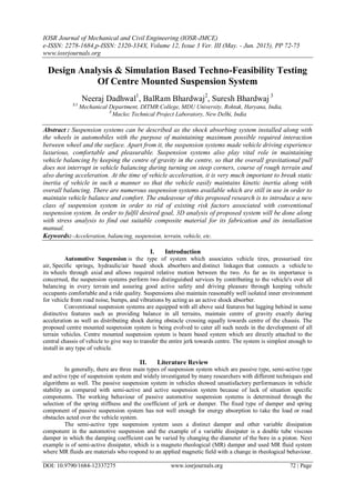
  • 3. Design Analysis & Simulation Based Techno-Feasibility Testing Of Centre… DOI: 10.9790/1684-12337275 www.iosrjournals.org 74 | Page Fig: Implementation of Centre Mounted Suspension system. V. Mathematical Calculations Fabrication As per the principle of leverage, it is being proved that using leaver, torque could be transferred from one point to another. Fig: Graphical Presentation of Leverage system. If a and b are the leaver from the fulcrum to points A & B and if force FA implanted to A is the incidental force and FB is received & B is the output, the ratio of the velocities of points A and B is given by a/b, so the ratio of the outlet force to the inlet force or mechanical advantage generated due to leverage, is can be given by VI. Results & Discussion Fig: Stress Analysis of Leaver joints and leaver rod using ANSYS.
  • 4. Design Analysis & Simulation Based Techno-Feasibility Testing Of Centre… DOI: 10.9790/1684-12337275 www.iosrjournals.org 75 | Page As per the Stress analysis and torque transmission analysis, it is being proved that the centre mounted suspension system provides major advantages during sharp turns and bumpy rides where other conventional suspension system get failed. In comparison with existing suspension systems, the centre mounted suspension system is maintaining its uniqueness throughout, weather it is design or mode of installation. Unlike conventional suspension systems, the proposed system is directly attached with the centre of vehicle chassis and due to which the overall jerk, displacement and vibrations generated due to terrain and driving condition, the vehicle never get miss-balanced because of the distinctive specified design of the proposed suspension system. The proposed system is based upon leverage phenomenon, in which the shaft which attached to the centre, act as a leaver and the suspension spring, which installed at predefined and calculated place in between the joint and the wheel base is act as a PIVOT which allows to transfer all the jerk and vibration direct to the centre while absorbing most of the jerk in between. VII. Conclusion There is tremendous scope to implement centre mounted suspension system in four wheelers and heavy loading vehicles in order to make ride more economic, luxurious, safe and advantageous. As far as the future scope is concerned, the system is capable enough to tackle all the existing problems related to conventional suspension systems in a single go. References Journal Papers: [1]. B. Chen, X. Liu, S. Tong, and C. Lin, “Observer-based stabilization of T–S fuzzy systems with input delay,” IEEE Trans. Fuzzy Syst., vol. 16, no. 3, pp. 652–663, Jun. 2008. [2]. Vehicle Suspension Systems Control: A Review Ayman A. Aly, and Farhan A. Salem, INTERNATIONAL JOURNAL OF CONTROL, AUTOMATION AND SYSTEMS VOL.2 NO.2 July 2013 ISSN 2165-8277 (Print) ISSN 2165-8285 (Online) http://www.researchpub.org/journal/jac/jac.html. Books: [3]. J. J. Uicker, G. R. Pennock, and J. E. Shigley, 2003, Theory of Machines and Mechanisms, Oxford University Press, New York Theses: [4]. Robust Control Design for Vehicle Active Suspension Systems with Uncertainty, Hongyi Li School of Creative Technologies University of Portsmouth A thesis submitted for the degree of Doctor of Philosophy June 2012.