
Recomendados
Más contenido relacionado
La actualidad más candente
La actualidad más candente (20)
Destacado
Similar a Gears presentation
Similar a Gears presentation (20)
Más de NISHANT552
Más de NISHANT552 (6)
Último
Último (20)
Gears presentation
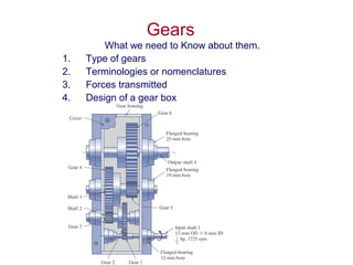
- 1. Gears What we need to Know about them. 1. Type of gears 2. Terminologies or nomenclatures 3. Forces transmitted 4. Design of a gear box
- 2. Type of Gears • Spurs • Helical • Bevel • And Worm Gears
- 3. Spur Gears Are used in transmitting torque between parallel shafts
- 4. Helical Gears Are used in transmitting torques between parallel or non parallel shafts, they are not as noisy as spur gears
- 5. Fig. 13.2
- 6. Bevel Gears • Are used to transmit rotary motion between intersecting shafts Teeth are formed on conical surfaces, the teeth could be straight or spiral.
- 7. Worm Gears Are used for transmitting motion between non parallel and non transmitting shafts, Depending on the number of teeth engaged called single or double. Worm gear mostly used when speed ratio is quiet high, 3 or more
- 8. Nomenclature Smaller Gear is Pinion and Larger one is the gear In most application the pinion is the driver, This reduces speed but it increases torque.
- 9. Internal Spur Gear System
- 10. pitch circle, theoretical circle upon which all calculation is based p, Circular pitch, p the distance from one teeth to the next, along the pitch circle. p=πd/N m, module=d/N pitch circle/number of teeth p= πm P, Diametral Pitch P=N/d pP= π
- 11. Angle Φ has the values of 20 or 25 degrees. Angle 14.5 have been also used. Gear profile is constructed from the base circle. Then additional clearance are given.
- 12. How Gear Profile is constructed A1B1=A1A0, A2B2=2 A1A0 , etc
- 13. Standard Gear Teeth Item 20o full depth 20o Stub 25o full depth Addendum a 1/P 0.8/P 1/P Dedendum 1.25/P 1/P 1.25/P Clearance f 0.25/P 0.2/P 0.25/P Working depth 2/P 1.6/P 2/P Whole depth 2.25/P 1.8/P 2.25/P Tooth thickness 1.571/P 1.571/P 1.571/P Face width 9/P<b<13/P 9/P<b<13/P 9/P<b<13/P
- 15. Planetary Gear train You can get high torque ratio in a smaller space There are two inputs to the planetary gears, RPM of sun and Ring, The out put is the speed of the arm.
- 16. Example of planetary Gear train Gear 1, sun , RPM 1200, Number of teeth 20, Planet Gear , Number of teeth 30 Ring Gear, Rotates RPM 120, and teeth of 80, ¼ horse power, find the speed of the arm and torque on the ring. Alternatively you may have Certain Out put Torque requirements
- 17. Transmitted Load • With a pair of gears or gear sets, Power is transmitted by the force developed between contacting Teeth
- 18. d in, RPM rev./min, V in/sec d in, n rpm, V fpm 95491000 33000 63000 12 60 2 *2/ sin cos TnVF KW V hp F Tn hp dn V RPM ddV FF FF t t nr nt == = = = == = = π π ω φ φ Toque lb-in V fpm T= N.m, V m/s, F Newton These forces have to be corrected for dynamic effects , we discuss later, considering AGMA factors
- 19. Some Useful Relations • F=33000hp/V V fpm English system • Metric System • KW=(FV)/1000=Tn/9549 • F newton, V m/s, n rpm, T, N.m • hp= FV/745.7=Tn/7121
- 20. Bending Strength of the a Gear Tooth Earlier Stress Analysis of the Gear Tooth was based on A full load is applied to the tip of a single tooth The radial load is negligible The load is uniform across the width Neglect frictional forces The stress concentration is negligible This equation does not consider stress concentration, dynamic effects, etc. 23 6 12/ 2/)( bt F bt tLF I Mc tt ===σ
- 21. Design for the Bending Strength of a Gear Tooth: The AGMA Method = = = = = = = = = = = = J K K m b P K K F J KK bm KKF J KK b P KKF m s v t ms vt ms vt 0 0 0 0.1 σ σ σ U.S. Customary SI units Bending stress at the root of the tooth Transmitted tangential load Overload factor Velocity factor Diameteral pitch, P Face width Metric modue Size factor Mounting factor Geometry factor
- 22. Your stress should not exceed allowable stress = = = = = = R T L t all RT Lt all K K K S KK KS σ σ Allowable bending stress Bending Strength Life factor Temperature factor Reliability factor
- 23. Overload Factor - Ko
- 24. Dynamic Factor - Kv -Even with steady loads tooth impact can cause shock loading -Impact strength depends on quality of the gear and the speed of gear teeth (pitch line velocity) -Gears are classified with respect to manufacturing tolerances: -Qv 3 – 7, commercial quality -Qv 8 – 12, precision -Graphs are available which chart Kv for different quality factors
- 25. Load Distribution Factor - Km -Failure greatly depends on how load is distributed across face -Accurate mounting helps ensure even distribution -For larger face widths even distribution is difficult to attain -Note formula depends on face width which has to be estimated for initial iteration -Form goal: b < Dp; 6 < b*P < 16
- 26. Reliability Factor - KR -Adjusts for reliability other than 99% - KR = 0.658 – 0.0759 ln (1-R) 0.5 < R <0.99 - KR = 0.50 – 0.109 ln (1-R) 0.99 < R < 0.9999
- 27. AGMA Geometry Factor - J -Updated Lewis Form Factor includes effect of stress concentration at fillet -Different charts for different pressure angles -Available for Precision Gears where we can assume load sharing (upper curves) -HPSTC – highest point of single tooth contact -Account for meshing gear and load sharing (contact ratio > 1) -Single tooth contact conservative assumption (bottom curve) -J = 0.311 ln N + 0.15 (20 degree) -J = 0.367 ln N + 0.2016 (25 degree)
- 28. Bending Strength No. – St, Fatigue bending strength -Tabulated Data similar to fatigue strength -Range given because value depends on Grade -Based on life of 107 cycles and 99% reliability
- 29. St – Analytical Estimate -Through hardened steel gears -Different charts for different manufacturing methods -Grade 1 – good quality St = 77.3 HB + 12,800 -Grade 2 – premium quality St = 102 HB + 16,400
- 30. Bending Strength Life Factor- KL -Adjusts for life goals other than 107 cycles -Fatigue effects vary with material properties and surface finishes -KL = 1.6831 N -0.0323 N>3E6 Note: @ 2000 rpm reach 3 million cycles in 1 day of service
- 31. Example: A conveyor drive involving heavy-shock torsional loading is operated by an electric motor, the speed ratio is 1:2 and the pinion has Diameteral pitch P=10 in-1 , and number of teeth N=18 and face width of b=1.5 in. The gear has Brinnel hardness of 300 Bhn. Find the maximum horspower that can be transmitted, using AGMA formula.
- 32. Gear Box Design
Notas del editor
- There are comprehensive charts available with application factors. These encapsulate the load on the driven machine. Power sources think of hand driving bike wheel. Finger on spokes continuously – uniform load; hand driving tire – 3 times per cycle requires higher value of instantaneous force; hand driving tire – 1 time per cycle require even higher instantaneous value of force. Lifts with high lifting speeds have dynamic effects (oscillation on elastic rope/chain) which cause overload
- E – A: are different manufacturing operations with increasing levels of precision E: Form cutters used on milling machines cut teeth then index gear D: shaping cutters - Fellows gear shaper uses a vertically oscillating ram that is forced radially inward to the tooth depth and then rotated with gear to form teeth C , B: have finishing methods applied to keep tooth form precise honing or grinding where gear is run meshed with and abrasive substance; shaving is designed to remove fine chips from the surface A: kept to tight tolerances
- Ideally your face width should be less than your pinion diameter Values up to 1.5 Dp are not too bad but the value should definitely be less than 2Dp Ideally face-width times Pitch (b*P) should be between 9 and 12. Initial estimate of fP = 11 can be used.
- Formula allow J to be programmed – quicker iteration to solution
- Quality Grade varies between 0 – 3 depending on how closely quality items like surface hardness, core hardness, etc. are controlled 0 – indicates no control 1 – good quality (modest control) 2 – premium quality (close control) 3 (super quality) – absolute control
- Hb – Brinnell Hardness We have seen earlier in the semester that HB is related to Su and subsequently to Se Analytical formula allow you to quickly modify design for iterative solution
- Analytic formulas help with iterative nature of gearing solutions