SlideShare una empresa de Scribd logo
1 de 10
ANALYSIS OF TRUSS
Syed Raheel Zafar
WHAT IS TRUSS?
• A truss is a structure comprising one or more
triangular units constructed with straight
members whose ends are connected at joints.
• If all the bars lie in a plane, the structure is a
planar truss.
• The main parts of a planar truss.
ANALYSIS OF FRAME
• A FRAME IS A STRUCTURE MADE OF SEVERAL BARS/ RODS
WELDED / RIVETTED TOGETHER
• THE BARS ARE ANGLE IRONS/ CHANNELS OF “I” OR “T”
SECTIONS. THESE ARE CALLED MEMBERS
• ON APPLICATION OF LOAD ON TO THE STRUCTURE, THE
MEMBERS REMAIN LOADED WITH TENSILE/ COMPRESSIVE
LOAD
• MEMBERS UNDER TENSION
• MEMBERS UNDER COMPRESSION
• THE STRUCTURE FORMED BY THE MEMBERS IS CALLED
“TRUSS”
• EXTENSIVELY USED IN ROOF, BRIDGE, SHEDS ETC.
STRESSES IN A FRAME
• UNDER APPLICATION OF LOAD THE STRUCTURE
TENDS TO DEFORM. THE MATERIAL OF THE FRAME
TENDS TO KEEP THE FRAME RIGID ( PREVENTS
DEFORMATION)
• AN INTERNAL RESISTIVE FORCE IS SET IN IN THE
MATERIAL . THIS INDUCES STRESS.
• σ = INTERNAL RESISTANCE / AREA
• LOAD CAN BE PULL / PUSH (TENSILE/ COMPRESSIVE)
• FOR JOINTS TO BE IN EQUILIBRIUM THE MEMBERS
MAY CARRY ZERO LOAD/ TENSILE/ COMPRESSIVE
LOAD.
CONVENTIONS
• ANALYST HAS TO IDENTIFY THE SITUATION ,
MAKE A MENTAL PICTURE OF THE FORCES
AND DECIDE THE ARROWS.
• A LOAD WITH ARROW AWAY FROM THE
JOINT IS TENSILE
• A LOAD WITH ARROW TOWARDS THE JOINT
IS COMPRESSIVE
ASSUMPTIONS
MEMBERS ARE RIGIDILY JOINT (Every member
of the truss is then in pure compression or pure
tension – shear, bending moment, and other
more complex stresses are all practically zero. )
•LOADS ACT ON THE JOINTS ONLY
•WEIGHT OF THE MEMBER AS COMPARED TO
THE EXTERNAL LOADS IS NEGLIGIBLE AND NOT
CONSIDERED FOR CALCULATIONS.
SOLUTIONS
ANALYTICAL
• USE OF TRIGONOMETRY/
GEOMETRY/ ALGEBRA
• TWO METHODS (JOINT &
SECTION METHODS)
• THE METHODS CAN BE
CUMBERSOME AND LENGTHY
AND LEAD TO ERRORS
• A COMPARISON ON NEXT
SLIDE
GRAPHICAL
• USE OF CONCEPT OF ENGG DRG
• USE OF SPACE, VECTOR DIAGRAM
AND A LOAD TABLE
• VECTOR DIAGRAM OF EACH JOINT
(MAXWELL DIAGRAM) AND
COMPOSITE VECTOR DIAGRAM
GIVES THE SOLUTION
• SELECT THE 1ST
JOINT WITH 2 UNK
FORCES AND THEN PROCEED TO THE
NEXT JOINT
• IT IS SIMPLE , EASY AND FULL PROOF
• INITALLY ANALYTICAL METOD TOBE
USED FOR CALCULATION OF
REACTIONS
ANALYTICAL SOLUTIONS
JOINT METHOD
• FORCES OF EA JOINT IS ANALYSID
ONE BY ONE
• SELECT A JOINT WITH 2 UNK
FORCES
• ANALYSE THE FORCES AT THAT
JOINT MATHEMATEICALLY AND
THEN PROCEED TO THE NEXT
• FOR COMPLEX FRAME THIS
METHOD IS VERY LONG AND CAN
LEAD TO MATHEMATICAL ERRORS
SECTION METHOD
• THE FRAME IS CUT INTO
SECTIONS
• EA SECTION IS THEREAFTER
ANALYSED USING FBD
• MOMENTS OF EACH MEMBER
W.R.T. A REF POINT IS
CALCULATED AND THE
FORCES ARE BVDETERMINED
• SECTION LINE MUST NOT CUT
MORE THAN 3 MEMBERS
• IT IS VERY TEDIOUS FOR
COMPLEX STRUCTURES
LEARNING OUTCOME
• Types of joints and supports
• Zero force members
• Material choice
• Factor of safety
• Design analysis
• Trial and error

Más contenido relacionado

La actualidad más candente

presentation based on Truss and Frame
presentation based on Truss and Framepresentation based on Truss and Frame
presentation based on Truss and Frame
Mohotasimur Anik
 

La actualidad más candente (20)

Structural analysis 1
Structural analysis   1Structural analysis   1
Structural analysis 1
 
Centroid & Centre of Gravity
Centroid & Centre of GravityCentroid & Centre of Gravity
Centroid & Centre of Gravity
 
Analysis of statically indeterminate structures
Analysis of statically indeterminate structuresAnalysis of statically indeterminate structures
Analysis of statically indeterminate structures
 
Unit 3 Compound stresses
Unit 3  Compound stressesUnit 3  Compound stresses
Unit 3 Compound stresses
 
presentation based on Truss and Frame
presentation based on Truss and Framepresentation based on Truss and Frame
presentation based on Truss and Frame
 
Combined bending and direct stresses
Combined bending and direct stressesCombined bending and direct stresses
Combined bending and direct stresses
 
Slope deflection method
Slope deflection methodSlope deflection method
Slope deflection method
 
Shear stresses in beams
Shear stresses in beamsShear stresses in beams
Shear stresses in beams
 
Lecture notes on trusses
Lecture notes on trussesLecture notes on trusses
Lecture notes on trusses
 
Moment Distribution Method
Moment Distribution MethodMoment Distribution Method
Moment Distribution Method
 
1
11
1
 
Bending stresses
Bending stressesBending stresses
Bending stresses
 
Design of steel beams
Design of steel beamsDesign of steel beams
Design of steel beams
 
Pin joint frames
Pin joint framesPin joint frames
Pin joint frames
 
3.1 betti's law and maxwell's receprocal theorem
3.1 betti's law and maxwell's receprocal theorem3.1 betti's law and maxwell's receprocal theorem
3.1 betti's law and maxwell's receprocal theorem
 
Unit 1- simple stress and strain
Unit 1- simple stress and strainUnit 1- simple stress and strain
Unit 1- simple stress and strain
 
Trusses and its applications
Trusses and its applicationsTrusses and its applications
Trusses and its applications
 
Truss
TrussTruss
Truss
 
SFD & BMD Shear Force & Bending Moment Diagram
SFD & BMD Shear Force & Bending Moment DiagramSFD & BMD Shear Force & Bending Moment Diagram
SFD & BMD Shear Force & Bending Moment Diagram
 
Beam and its types
Beam and its typesBeam and its types
Beam and its types
 

Destacado

project report on truss bridge
project report on truss bridgeproject report on truss bridge
project report on truss bridge
rajdutt1111
 
Building structure project 1 report
Building structure project 1 reportBuilding structure project 1 report
Building structure project 1 report
Adelinetingg
 
Structural analysis (method of sections)
Structural analysis (method of sections)Structural analysis (method of sections)
Structural analysis (method of sections)
physics101
 
Lunch&LearnPoster_newADD
Lunch&LearnPoster_newADDLunch&LearnPoster_newADD
Lunch&LearnPoster_newADD
Alison Henry
 

Destacado (20)

Maxwell diagram lec
Maxwell diagram lecMaxwell diagram lec
Maxwell diagram lec
 
Trusses
TrussesTrusses
Trusses
 
PPT OF TRUSSES
PPT OF TRUSSESPPT OF TRUSSES
PPT OF TRUSSES
 
Trusses
TrussesTrusses
Trusses
 
project report on truss bridge
project report on truss bridgeproject report on truss bridge
project report on truss bridge
 
Modelling
ModellingModelling
Modelling
 
Building structure project 1 report
Building structure project 1 reportBuilding structure project 1 report
Building structure project 1 report
 
Application of the trusses
Application of the trussesApplication of the trusses
Application of the trusses
 
Structural analysis (method of sections)
Structural analysis (method of sections)Structural analysis (method of sections)
Structural analysis (method of sections)
 
Structure analysis assignment 3 support reaction calculation
Structure analysis assignment 3 support reaction calculationStructure analysis assignment 3 support reaction calculation
Structure analysis assignment 3 support reaction calculation
 
Back-analysis of the collapse of a metal truss structure
Back-analysis of the collapse of a metal truss structureBack-analysis of the collapse of a metal truss structure
Back-analysis of the collapse of a metal truss structure
 
Pratt truss optimization using
Pratt truss optimization usingPratt truss optimization using
Pratt truss optimization using
 
Sustainability Advantage of Post-tensioning in Buildings
Sustainability Advantage of Post-tensioning in BuildingsSustainability Advantage of Post-tensioning in Buildings
Sustainability Advantage of Post-tensioning in Buildings
 
BSU-AQR-Case-Study
BSU-AQR-Case-StudyBSU-AQR-Case-Study
BSU-AQR-Case-Study
 
The BIG BOSS TURKEY
The BIG BOSS TURKEYThe BIG BOSS TURKEY
The BIG BOSS TURKEY
 
Peyton's Waterford3 Refueling presentation
Peyton's Waterford3 Refueling presentation Peyton's Waterford3 Refueling presentation
Peyton's Waterford3 Refueling presentation
 
Lunch&LearnPoster_newADD
Lunch&LearnPoster_newADDLunch&LearnPoster_newADD
Lunch&LearnPoster_newADD
 
Las responsabilidades del ingeniero parte 3
Las responsabilidades del ingeniero parte 3 Las responsabilidades del ingeniero parte 3
Las responsabilidades del ingeniero parte 3
 
Afh 2012 09-05-aiasf_kj-zt
Afh 2012 09-05-aiasf_kj-ztAfh 2012 09-05-aiasf_kj-zt
Afh 2012 09-05-aiasf_kj-zt
 
News SSL 08 2016
News SSL 08 2016News SSL 08 2016
News SSL 08 2016
 

Similar a Analysis of Truss

Mechanic Machine
Mechanic MachineMechanic Machine
Mechanic Machine
Malaysia
 
Triangulation and trilateration pdf...
Triangulation and trilateration pdf...Triangulation and trilateration pdf...
Triangulation and trilateration pdf...
Gokul Saud
 

Similar a Analysis of Truss (20)

engineering statics: structures
engineering statics: structuresengineering statics: structures
engineering statics: structures
 
L8 Applied mechanical measurement
L8 Applied mechanical measurementL8 Applied mechanical measurement
L8 Applied mechanical measurement
 
Slab.beam.stair.ppt
Slab.beam.stair.pptSlab.beam.stair.ppt
Slab.beam.stair.ppt
 
Space frames!
Space frames!Space frames!
Space frames!
 
Chapter 3
Chapter 3Chapter 3
Chapter 3
 
Triangulation and Trilateration
Triangulation and TrilaterationTriangulation and Trilateration
Triangulation and Trilateration
 
Lec11 Continuous Beams and One Way Slabs(1) (Reinforced Concrete Design I & P...
Lec11 Continuous Beams and One Way Slabs(1) (Reinforced Concrete Design I & P...Lec11 Continuous Beams and One Way Slabs(1) (Reinforced Concrete Design I & P...
Lec11 Continuous Beams and One Way Slabs(1) (Reinforced Concrete Design I & P...
 
Combined footing
Combined footingCombined footing
Combined footing
 
TRUSS ANALYSIS (TERM PAPER REPORT)
TRUSS ANALYSIS (TERM PAPER REPORT)TRUSS ANALYSIS (TERM PAPER REPORT)
TRUSS ANALYSIS (TERM PAPER REPORT)
 
Analysis of Truss
Analysis of TrussAnalysis of Truss
Analysis of Truss
 
L 2 degree of redundancy of plane truss
L 2 degree of redundancy of plane trussL 2 degree of redundancy of plane truss
L 2 degree of redundancy of plane truss
 
2_Introduction Classification of Structure.pptx
2_Introduction Classification of Structure.pptx2_Introduction Classification of Structure.pptx
2_Introduction Classification of Structure.pptx
 
Module-I SURVEYING-I [BTCVC304]
Module-I SURVEYING-I [BTCVC304]Module-I SURVEYING-I [BTCVC304]
Module-I SURVEYING-I [BTCVC304]
 
CAD
CAD CAD
CAD
 
Chain surveying and offset
Chain surveying and offsetChain surveying and offset
Chain surveying and offset
 
Finite Element analysis -Plate ,shell skew plate
Finite Element analysis -Plate ,shell skew plate Finite Element analysis -Plate ,shell skew plate
Finite Element analysis -Plate ,shell skew plate
 
Mechanic Machine
Mechanic MachineMechanic Machine
Mechanic Machine
 
Triangulation and trilateration pdf...
Triangulation and trilateration pdf...Triangulation and trilateration pdf...
Triangulation and trilateration pdf...
 
Assembly of Parts
Assembly of PartsAssembly of Parts
Assembly of Parts
 
Space frame
Space frameSpace frame
Space frame
 

Último

Call Now ≽ 9953056974 ≼🔝 Call Girls In New Ashok Nagar ≼🔝 Delhi door step de...
Call Now ≽ 9953056974 ≼🔝 Call Girls In New Ashok Nagar  ≼🔝 Delhi door step de...Call Now ≽ 9953056974 ≼🔝 Call Girls In New Ashok Nagar  ≼🔝 Delhi door step de...
Call Now ≽ 9953056974 ≼🔝 Call Girls In New Ashok Nagar ≼🔝 Delhi door step de...
9953056974 Low Rate Call Girls In Saket, Delhi NCR
 

Último (20)

University management System project report..pdf
University management System project report..pdfUniversity management System project report..pdf
University management System project report..pdf
 
Unit 1 - Soil Classification and Compaction.pdf
Unit 1 - Soil Classification and Compaction.pdfUnit 1 - Soil Classification and Compaction.pdf
Unit 1 - Soil Classification and Compaction.pdf
 
UNIT-III FMM. DIMENSIONAL ANALYSIS
UNIT-III FMM.        DIMENSIONAL ANALYSISUNIT-III FMM.        DIMENSIONAL ANALYSIS
UNIT-III FMM. DIMENSIONAL ANALYSIS
 
(INDIRA) Call Girl Aurangabad Call Now 8617697112 Aurangabad Escorts 24x7
(INDIRA) Call Girl Aurangabad Call Now 8617697112 Aurangabad Escorts 24x7(INDIRA) Call Girl Aurangabad Call Now 8617697112 Aurangabad Escorts 24x7
(INDIRA) Call Girl Aurangabad Call Now 8617697112 Aurangabad Escorts 24x7
 
Call Now ≽ 9953056974 ≼🔝 Call Girls In New Ashok Nagar ≼🔝 Delhi door step de...
Call Now ≽ 9953056974 ≼🔝 Call Girls In New Ashok Nagar  ≼🔝 Delhi door step de...Call Now ≽ 9953056974 ≼🔝 Call Girls In New Ashok Nagar  ≼🔝 Delhi door step de...
Call Now ≽ 9953056974 ≼🔝 Call Girls In New Ashok Nagar ≼🔝 Delhi door step de...
 
Booking open Available Pune Call Girls Koregaon Park 6297143586 Call Hot Ind...
Booking open Available Pune Call Girls Koregaon Park  6297143586 Call Hot Ind...Booking open Available Pune Call Girls Koregaon Park  6297143586 Call Hot Ind...
Booking open Available Pune Call Girls Koregaon Park 6297143586 Call Hot Ind...
 
The Most Attractive Pune Call Girls Budhwar Peth 8250192130 Will You Miss Thi...
The Most Attractive Pune Call Girls Budhwar Peth 8250192130 Will You Miss Thi...The Most Attractive Pune Call Girls Budhwar Peth 8250192130 Will You Miss Thi...
The Most Attractive Pune Call Girls Budhwar Peth 8250192130 Will You Miss Thi...
 
Thermal Engineering -unit - III & IV.ppt
Thermal Engineering -unit - III & IV.pptThermal Engineering -unit - III & IV.ppt
Thermal Engineering -unit - III & IV.ppt
 
NFPA 5000 2024 standard .
NFPA 5000 2024 standard                                  .NFPA 5000 2024 standard                                  .
NFPA 5000 2024 standard .
 
Coefficient of Thermal Expansion and their Importance.pptx
Coefficient of Thermal Expansion and their Importance.pptxCoefficient of Thermal Expansion and their Importance.pptx
Coefficient of Thermal Expansion and their Importance.pptx
 
Generative AI or GenAI technology based PPT
Generative AI or GenAI technology based PPTGenerative AI or GenAI technology based PPT
Generative AI or GenAI technology based PPT
 
Thermal Engineering Unit - I & II . ppt
Thermal Engineering  Unit - I & II . pptThermal Engineering  Unit - I & II . ppt
Thermal Engineering Unit - I & II . ppt
 
Glass Ceramics: Processing and Properties
Glass Ceramics: Processing and PropertiesGlass Ceramics: Processing and Properties
Glass Ceramics: Processing and Properties
 
Top Rated Pune Call Girls Budhwar Peth ⟟ 6297143586 ⟟ Call Me For Genuine Se...
Top Rated  Pune Call Girls Budhwar Peth ⟟ 6297143586 ⟟ Call Me For Genuine Se...Top Rated  Pune Call Girls Budhwar Peth ⟟ 6297143586 ⟟ Call Me For Genuine Se...
Top Rated Pune Call Girls Budhwar Peth ⟟ 6297143586 ⟟ Call Me For Genuine Se...
 
data_management_and _data_science_cheat_sheet.pdf
data_management_and _data_science_cheat_sheet.pdfdata_management_and _data_science_cheat_sheet.pdf
data_management_and _data_science_cheat_sheet.pdf
 
Roadmap to Membership of RICS - Pathways and Routes
Roadmap to Membership of RICS - Pathways and RoutesRoadmap to Membership of RICS - Pathways and Routes
Roadmap to Membership of RICS - Pathways and Routes
 
Online banking management system project.pdf
Online banking management system project.pdfOnline banking management system project.pdf
Online banking management system project.pdf
 
Java Programming :Event Handling(Types of Events)
Java Programming :Event Handling(Types of Events)Java Programming :Event Handling(Types of Events)
Java Programming :Event Handling(Types of Events)
 
chapter 5.pptx: drainage and irrigation engineering
chapter 5.pptx: drainage and irrigation engineeringchapter 5.pptx: drainage and irrigation engineering
chapter 5.pptx: drainage and irrigation engineering
 
Intze Overhead Water Tank Design by Working Stress - IS Method.pdf
Intze Overhead Water Tank  Design by Working Stress - IS Method.pdfIntze Overhead Water Tank  Design by Working Stress - IS Method.pdf
Intze Overhead Water Tank Design by Working Stress - IS Method.pdf
 

Analysis of Truss

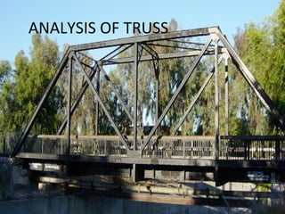
  • 3. WHAT IS TRUSS? • A truss is a structure comprising one or more triangular units constructed with straight members whose ends are connected at joints. • If all the bars lie in a plane, the structure is a planar truss. • The main parts of a planar truss.
  • 4. ANALYSIS OF FRAME • A FRAME IS A STRUCTURE MADE OF SEVERAL BARS/ RODS WELDED / RIVETTED TOGETHER • THE BARS ARE ANGLE IRONS/ CHANNELS OF “I” OR “T” SECTIONS. THESE ARE CALLED MEMBERS • ON APPLICATION OF LOAD ON TO THE STRUCTURE, THE MEMBERS REMAIN LOADED WITH TENSILE/ COMPRESSIVE LOAD • MEMBERS UNDER TENSION • MEMBERS UNDER COMPRESSION • THE STRUCTURE FORMED BY THE MEMBERS IS CALLED “TRUSS” • EXTENSIVELY USED IN ROOF, BRIDGE, SHEDS ETC.
  • 5. STRESSES IN A FRAME • UNDER APPLICATION OF LOAD THE STRUCTURE TENDS TO DEFORM. THE MATERIAL OF THE FRAME TENDS TO KEEP THE FRAME RIGID ( PREVENTS DEFORMATION) • AN INTERNAL RESISTIVE FORCE IS SET IN IN THE MATERIAL . THIS INDUCES STRESS. • σ = INTERNAL RESISTANCE / AREA • LOAD CAN BE PULL / PUSH (TENSILE/ COMPRESSIVE) • FOR JOINTS TO BE IN EQUILIBRIUM THE MEMBERS MAY CARRY ZERO LOAD/ TENSILE/ COMPRESSIVE LOAD.
  • 6. CONVENTIONS • ANALYST HAS TO IDENTIFY THE SITUATION , MAKE A MENTAL PICTURE OF THE FORCES AND DECIDE THE ARROWS. • A LOAD WITH ARROW AWAY FROM THE JOINT IS TENSILE • A LOAD WITH ARROW TOWARDS THE JOINT IS COMPRESSIVE
  • 7. ASSUMPTIONS MEMBERS ARE RIGIDILY JOINT (Every member of the truss is then in pure compression or pure tension – shear, bending moment, and other more complex stresses are all practically zero. ) •LOADS ACT ON THE JOINTS ONLY •WEIGHT OF THE MEMBER AS COMPARED TO THE EXTERNAL LOADS IS NEGLIGIBLE AND NOT CONSIDERED FOR CALCULATIONS.
  • 8. SOLUTIONS ANALYTICAL • USE OF TRIGONOMETRY/ GEOMETRY/ ALGEBRA • TWO METHODS (JOINT & SECTION METHODS) • THE METHODS CAN BE CUMBERSOME AND LENGTHY AND LEAD TO ERRORS • A COMPARISON ON NEXT SLIDE GRAPHICAL • USE OF CONCEPT OF ENGG DRG • USE OF SPACE, VECTOR DIAGRAM AND A LOAD TABLE • VECTOR DIAGRAM OF EACH JOINT (MAXWELL DIAGRAM) AND COMPOSITE VECTOR DIAGRAM GIVES THE SOLUTION • SELECT THE 1ST JOINT WITH 2 UNK FORCES AND THEN PROCEED TO THE NEXT JOINT • IT IS SIMPLE , EASY AND FULL PROOF • INITALLY ANALYTICAL METOD TOBE USED FOR CALCULATION OF REACTIONS
  • 9. ANALYTICAL SOLUTIONS JOINT METHOD • FORCES OF EA JOINT IS ANALYSID ONE BY ONE • SELECT A JOINT WITH 2 UNK FORCES • ANALYSE THE FORCES AT THAT JOINT MATHEMATEICALLY AND THEN PROCEED TO THE NEXT • FOR COMPLEX FRAME THIS METHOD IS VERY LONG AND CAN LEAD TO MATHEMATICAL ERRORS SECTION METHOD • THE FRAME IS CUT INTO SECTIONS • EA SECTION IS THEREAFTER ANALYSED USING FBD • MOMENTS OF EACH MEMBER W.R.T. A REF POINT IS CALCULATED AND THE FORCES ARE BVDETERMINED • SECTION LINE MUST NOT CUT MORE THAN 3 MEMBERS • IT IS VERY TEDIOUS FOR COMPLEX STRUCTURES
  • 10. LEARNING OUTCOME • Types of joints and supports • Zero force members • Material choice • Factor of safety • Design analysis • Trial and error