The Power of Finite Element Analysis Simulation
•
0 recomendaciones•85 vistas

fem gamma ai

Recomendados
Recomendados
Más contenido relacionado
Similar a The Power of Finite Element Analysis Simulation
Similar a The Power of Finite Element Analysis Simulation (20)
Más de Shiva krishna gupta
Más de Shiva krishna gupta (11)
Último
Último (20)
The Power of Finite Element Analysis Simulation
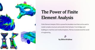
- 1. The Power of Finite Element Analysis Finite Element Analysis (FEA) is apowerful simulation tool that can be used to model complex structures and predict their behavior.From bridges and buildings to machines and medical implants, FEAhas revolutionized the world of engineering. by Shiva Krishna
- 2. Understanding FEA Simulation FEAsimulates the real-world behavior of asystem by dividing it into smaller, manageable elements. Mathematics Boundary conditions and material properties are represented by mathematical equations that are solved for each element. Validation FEAresults are validated through physical testing to guarantee their accuracy and reliability. Application FEAis used to optimize performance, reduce costs, and minimize risk in awide range of industries.
- 3. The FEA Process 1 Model Building ACAD model is created and refined to accurately represent the geometry and components of the system. 2 Mesh Generation The model is divided into small, interconnected elements that can be analyzed individually using FEAsoftware. 3 Analysis Boundary conditions, material properties, and loads are applied to the mesh, and the software solves the equations for each element to predict the system's response. 4 Results The results are visualized and analyzed to gain insights into the system's behavior, and modifications are made to improve its performance.
- 4. Mesh Generation Techniques Prefabricated Meshes Pre-made meshes supplied by software vendors that can be used to quickly generate amodel. Structured Meshes Meshes with auniform and regular structure that can be easily refined and optimized. Unstructured Meshes Meshes that follow the contours of the model, providing amore accurate representation but requiring more computational power. Adaptive Meshing Amesh that is refined in areas of interest in order to capture important features, while using larger elements in areas that are less critical.
- 5. Types of Analysis with FEA Thermal Simulates the effects of temperature changes on asystem, such as expansion or contraction, and helps to optimize cooling or insulation. Structural Examines the behavior of astructure under different loads, such as bending or compression, and identifies potential points of failure. Fluid Dynamics Simulates the flow of fluids around a structure, such as air around acar or blood through aheart valve, and helps to optimize performance and reduce drag.
- 6. Applications of FEA in Engineering 1 Product Design FEAis used to optimize the design of products, ensuring that they are safe, efficient, and durable. 2 Structural Analysis FEAis used to analyze the behavior of structures, such as bridges and buildings, to ensure they are safe and meet building codes. 3 Manufacturing FEAis used to optimize the production process, reducing costs and improving quality control. 4 Medical Devices FEAis used to design and test medical implants, such as hip replacements, to ensure they are safe and effective.
- 7. Limitations of FEA Assumptions FEAis only as accurate as the assumptions and simplifications made during the modeling and analysis process. Data Collection FEAis constrained by the availability and quality of data, and inaccuracies in datacan impact the accuracy of results. Computation Power FEArequires significant computational power to perform complex simulations, which can limit the scope and speed of analysis.
- 8. Conclusion and Future Developments Future of FEA Advances in technology are reducing the limitations of FEA, making it faster, more accurate, and more accessible than ever before. Continued Usage FEAis and will continue to be acritical tool for engineers and designers, enabling them to create safe, efficient, and innovative products and structures.