SlideShare una empresa de Scribd logo
1 de 3
1. Three resistances of 10, 15 and 20 ohms are connected in star across a three-phase supply
       of 200V per phase as shown in the figure. The supply neutral is earthed while the load
       neutral is isolated. Find the currents in each load branch and the voltage of load neutral
       above earth. Use the method of symmetrical components.


VAN = 200
VBN = 200a2
VCN = 200a
Let us represent it this way, it will be easier.

Apply KVL to the loop AacC
VAN – 10 Ia +20Ic – VCN = 0
And also apply KVL to the loop AabB
VAN – 10Ia +15Ib – VBN = 0
Now write the currents in symmetrical components and also we know that the zero
sequence components will be zero as the load neutral current is not grounded.And if you
we apply KCL at load neutral we get Ia0 = 0.

Hence we get,
Ia1(20a - 10) + Ia2(20a2 - 10) = 200a – 200
And
Ia1(15a2 – 10 ) + Ia2(15a – 10 ) = 200a2 – 200
Solving the above equation in terms of ‘a’ and in the end substitute ‘a’ value.
Ia1 = 13.8461 - 0.0000i
Ia2 = 2.3077 + 1.3324i
Hence Ia = Ia1+Ia2 = 16.1539 + 1.3323i
Ib = Ib1 + Ib2 = - 9.2302 - 10.6584i
Ic = Ic1 +Ic2 = - 6.9230 + 9.3262i

To get Vn(voltage of the neutral with respect to ground) – start from ground and come to
neutral of load
Vn = 200 - 10*Ia
Vn = 38.4614 -13.3234i
Magnitude = 40.7037


    2. The voltages at the terminals of a balanced load consisting of three 20 ohm Y-connected
       resistors are 200(0◦), 10(255.5◦) and 200(151◦) V. Find the line currents from the
       symmetrical components of the line voltages if the neutral of the load is isolated. What
       relation exists between the symmetrical components of the line and………..

    Solution :

    Convert star to delta and you get the value of all resistances which are balanced as 60 ohms

    Iab = 200/60 = 10/3 (00)

    Ibc = 100(255.50)/60 = 5/3(255.50)

    Ica = 200(1510)/60 = 10/3(1510)

    Using symmetrical components resolution formula involving A-1

    From this we get Iab1 = 2.7(15.10)

    Iab2 = 1.03(- 44.530)

    Ia1 = Iab1 – Ica1 = 4.67(-150)

    Ia2 = Iab2 – Ica2 = 1.784(-14.50)

    Ia = Ia1 + Ia2(zero seq. Comp. Currents will not appear in the lines of delta connected or star
    connected load with neutral isolated)

    Ia = 6.453(-14.870)

    Ib1 = a^2Ia1 = 4.67(-1350)

    Ib2 = aIb2 = 1.784(105.50)

    Ib = Ib1+Ib2 = 4.105(-156.90)

    Ic1 = a*Ia1 = 4.67(1050)

    Ic2 = a^2 Ia2 = 1.784(-134.50)

    Ic = Ic1+ Ic2 = 4.066(127.40)

    There the power dissipated in 3 phase 20 ohms resistors is
P = Ia^2(20)+ Ib^2(20) + Ic^2(20)

 = (6.453^2 + 4.1^2+ 4.066^2)(20)

 P = 1500W

Más contenido relacionado

La actualidad más candente

Chapter 2 transformer new
Chapter 2 transformer newChapter 2 transformer new
Chapter 2 transformer new
mkazree
 
Newton Raphson method for load flow analysis
Newton Raphson method for load flow analysisNewton Raphson method for load flow analysis
Newton Raphson method for load flow analysis
divyanshuprakashrock
 
Power system stability
Power system  stabilityPower system  stability
Power system stability
Deepak John
 
Power Flow in a Transmission line
Power Flow in a Transmission linePower Flow in a Transmission line
Power Flow in a Transmission line
Ayyarao T S L V
 

La actualidad más candente (20)

Presentation1
Presentation1Presentation1
Presentation1
 
Generation shift factor and line outage factor
Generation shift factor and line outage factorGeneration shift factor and line outage factor
Generation shift factor and line outage factor
 
Lecture 10
Lecture 10Lecture 10
Lecture 10
 
Chapter 2 transformer new
Chapter 2 transformer newChapter 2 transformer new
Chapter 2 transformer new
 
Fault analysis
Fault analysisFault analysis
Fault analysis
 
EDS Unit 1 (Part 1).pptx
EDS Unit 1 (Part 1).pptxEDS Unit 1 (Part 1).pptx
EDS Unit 1 (Part 1).pptx
 
power system analysis PPT
power system analysis PPTpower system analysis PPT
power system analysis PPT
 
Newton Raphson method for load flow analysis
Newton Raphson method for load flow analysisNewton Raphson method for load flow analysis
Newton Raphson method for load flow analysis
 
Circle Diagram
Circle DiagramCircle Diagram
Circle Diagram
 
Power system stability
Power system  stabilityPower system  stability
Power system stability
 
Dynamics of Electrical Drives
Dynamics of Electrical DrivesDynamics of Electrical Drives
Dynamics of Electrical Drives
 
Power Flow in a Transmission line
Power Flow in a Transmission linePower Flow in a Transmission line
Power Flow in a Transmission line
 
Power flow analysis
Power flow analysisPower flow analysis
Power flow analysis
 
Power system calculations
Power system calculationsPower system calculations
Power system calculations
 
WIDE AREA MANAGEMENT SYSTEM
WIDE AREA MANAGEMENT SYSTEMWIDE AREA MANAGEMENT SYSTEM
WIDE AREA MANAGEMENT SYSTEM
 
Exp 7 for Impulse Voltage Breakdown.pdf
Exp 7 for Impulse Voltage Breakdown.pdfExp 7 for Impulse Voltage Breakdown.pdf
Exp 7 for Impulse Voltage Breakdown.pdf
 
6 PHASE TRANSMISSION SYSTEM
6 PHASE TRANSMISSION SYSTEM6 PHASE TRANSMISSION SYSTEM
6 PHASE TRANSMISSION SYSTEM
 
Distribution System Voltage Drop and Power Loss Calculation
Distribution System Voltage Drop and Power Loss CalculationDistribution System Voltage Drop and Power Loss Calculation
Distribution System Voltage Drop and Power Loss Calculation
 
Two port networks
Two port networksTwo port networks
Two port networks
 
POWER (LOAD) FLOW STUDY
POWER (LOAD)  FLOW STUDYPOWER (LOAD)  FLOW STUDY
POWER (LOAD) FLOW STUDY
 

Destacado

Step1 Single Line Diagram
Step1 Single Line DiagramStep1 Single Line Diagram
Step1 Single Line Diagram
nanonon
 

Destacado (20)

Practice questions for unit ii
Practice questions for unit iiPractice questions for unit ii
Practice questions for unit ii
 
Questions unit3
Questions unit3Questions unit3
Questions unit3
 
Hydro E
Hydro EHydro E
Hydro E
 
EEP303: Fault studies
EEP303: Fault studiesEEP303: Fault studies
EEP303: Fault studies
 
EEP303: Exp1
EEP303: Exp1EEP303: Exp1
EEP303: Exp1
 
Questions unit4
Questions unit4Questions unit4
Questions unit4
 
Questions practice unit iv
Questions practice unit ivQuestions practice unit iv
Questions practice unit iv
 
Unit v
Unit vUnit v
Unit v
 
Unit4questions
Unit4questionsUnit4questions
Unit4questions
 
Unit1questions
Unit1questionsUnit1questions
Unit1questions
 
EEP306: Bit error rate
EEP306: Bit error rateEEP306: Bit error rate
EEP306: Bit error rate
 
Unit 2 Questions_Nagrath kothari
Unit 2 Questions_Nagrath kothariUnit 2 Questions_Nagrath kothari
Unit 2 Questions_Nagrath kothari
 
Solutions -unit4
Solutions  -unit4Solutions  -unit4
Solutions -unit4
 
Unit1 And 2 Sample Solutions
Unit1 And 2 Sample SolutionsUnit1 And 2 Sample Solutions
Unit1 And 2 Sample Solutions
 
Practice questions
Practice questionsPractice questions
Practice questions
 
Unit1 8
Unit1 8Unit1 8
Unit1 8
 
Step1 Single Line Diagram
Step1 Single Line DiagramStep1 Single Line Diagram
Step1 Single Line Diagram
 
TPs-TDs : Travaux Pratiques & Dérigés (version 2014-2017) Génie Electrique/Ex...
TPs-TDs : Travaux Pratiques & Dérigés (version 2014-2017) Génie Electrique/Ex...TPs-TDs : Travaux Pratiques & Dérigés (version 2014-2017) Génie Electrique/Ex...
TPs-TDs : Travaux Pratiques & Dérigés (version 2014-2017) Génie Electrique/Ex...
 
Problemas resueltos cortocircuito trifasico
Problemas resueltos cortocircuito trifasicoProblemas resueltos cortocircuito trifasico
Problemas resueltos cortocircuito trifasico
 
Unit 1, Power system Analysis
Unit 1, Power system AnalysisUnit 1, Power system Analysis
Unit 1, Power system Analysis
 

Similar a Unit 2 samplesolutions

Unit1 and 2 sample solutions
Unit1 and 2 sample solutionsUnit1 and 2 sample solutions
Unit1 and 2 sample solutions
Abha Tripathi
 
questions on diode analysis: Assignment6
questions on diode analysis: Assignment6questions on diode analysis: Assignment6
questions on diode analysis: Assignment6
Akash Kumar Verma
 

Similar a Unit 2 samplesolutions (20)

Unit1 and 2 sample solutions
Unit1 and 2 sample solutionsUnit1 and 2 sample solutions
Unit1 and 2 sample solutions
 
PERFORMANCE OF TRANSMISSION LINES:
PERFORMANCE OF TRANSMISSION LINES:PERFORMANCE OF TRANSMISSION LINES:
PERFORMANCE OF TRANSMISSION LINES:
 
Gate ee 2007 with solutions
Gate ee 2007 with solutionsGate ee 2007 with solutions
Gate ee 2007 with solutions
 
questions on diode analysis: Assignment6
questions on diode analysis: Assignment6questions on diode analysis: Assignment6
questions on diode analysis: Assignment6
 
BEF 23803 - Lecture 8 - Conservation of Complex Power.ppt
BEF 23803 - Lecture 8 - Conservation of Complex Power.pptBEF 23803 - Lecture 8 - Conservation of Complex Power.ppt
BEF 23803 - Lecture 8 - Conservation of Complex Power.ppt
 
ECNG 6503 #4
ECNG 6503 #4ECNG 6503 #4
ECNG 6503 #4
 
Calculations of a.c distributions methods & 3 phase unbalanced loads &amp...
Calculations of a.c distributions methods & 3 phase unbalanced loads &amp...Calculations of a.c distributions methods & 3 phase unbalanced loads &amp...
Calculations of a.c distributions methods & 3 phase unbalanced loads &amp...
 
11.Problems On Transformer On Load.PPT
11.Problems On Transformer On Load.PPT11.Problems On Transformer On Load.PPT
11.Problems On Transformer On Load.PPT
 
W ee network_theory_10-06-17_ls2-sol
W ee network_theory_10-06-17_ls2-solW ee network_theory_10-06-17_ls2-sol
W ee network_theory_10-06-17_ls2-sol
 
BEEE-UNIT 1.pptx
BEEE-UNIT 1.pptxBEEE-UNIT 1.pptx
BEEE-UNIT 1.pptx
 
3939.ppt
3939.ppt3939.ppt
3939.ppt
 
Delta connection (line and phase quantities)
Delta connection (line and phase quantities)Delta connection (line and phase quantities)
Delta connection (line and phase quantities)
 
Three phase System
Three phase SystemThree phase System
Three phase System
 
Unsymmetrical Fault Analysis
Unsymmetrical Fault AnalysisUnsymmetrical Fault Analysis
Unsymmetrical Fault Analysis
 
Eet3082 binod kumar sahu lecture_39
Eet3082 binod kumar sahu lecture_39Eet3082 binod kumar sahu lecture_39
Eet3082 binod kumar sahu lecture_39
 
T6 1 ph-ac
T6 1 ph-acT6 1 ph-ac
T6 1 ph-ac
 
Chapterhj jkhjhjhjh kjhjhjhljh jhkjhjhgftf rdrd
Chapterhj jkhjhjhjh kjhjhjhljh jhkjhjhgftf rdrdChapterhj jkhjhjhjh kjhjhjhljh jhkjhjhgftf rdrd
Chapterhj jkhjhjhjh kjhjhjhljh jhkjhjhgftf rdrd
 
1 potential & capacity 09
1 potential & capacity 091 potential & capacity 09
1 potential & capacity 09
 
Linear Algebra and Complex Variables
Linear Algebra and Complex VariablesLinear Algebra and Complex Variables
Linear Algebra and Complex Variables
 
Chapter 19-powerpoint-1234856218860660-2
Chapter 19-powerpoint-1234856218860660-2Chapter 19-powerpoint-1234856218860660-2
Chapter 19-powerpoint-1234856218860660-2
 

Más de Abha Tripathi

Más de Abha Tripathi (16)

Power system Stability, Equal area criteria
Power system Stability, Equal area criteriaPower system Stability, Equal area criteria
Power system Stability, Equal area criteria
 
Non Conventional (Renewable) Energy Sources 01
Non Conventional (Renewable) Energy Sources 01Non Conventional (Renewable) Energy Sources 01
Non Conventional (Renewable) Energy Sources 01
 
Conventional sources of energy (power generation) 01
Conventional sources of energy (power generation) 01Conventional sources of energy (power generation) 01
Conventional sources of energy (power generation) 01
 
Symmetrical components
Symmetrical componentsSymmetrical components
Symmetrical components
 
Representation of power system components
Representation of power system componentsRepresentation of power system components
Representation of power system components
 
Questions unit2 ch3
Questions unit2 ch3Questions unit2 ch3
Questions unit2 ch3
 
Renewable Sor
Renewable SorRenewable Sor
Renewable Sor
 
Gas and diesel Plant
Gas and diesel PlantGas and diesel Plant
Gas and diesel Plant
 
NPP, Nuclear Power Plant,
NPP, Nuclear Power Plant, NPP, Nuclear Power Plant,
NPP, Nuclear Power Plant,
 
Thermal power plant
Thermal power plantThermal power plant
Thermal power plant
 
Soln unit5
Soln unit5Soln unit5
Soln unit5
 
Questions From 1st Unit Nagrath
Questions From 1st Unit NagrathQuestions From 1st Unit Nagrath
Questions From 1st Unit Nagrath
 
Unit 3 Part 1
Unit 3 Part 1Unit 3 Part 1
Unit 3 Part 1
 
Grading The Insulator Problem
Grading The Insulator ProblemGrading The Insulator Problem
Grading The Insulator Problem
 
Dc Distribution
Dc DistributionDc Distribution
Dc Distribution
 
Dc Distributed Load
Dc Distributed LoadDc Distributed Load
Dc Distributed Load
 

Unit 2 samplesolutions

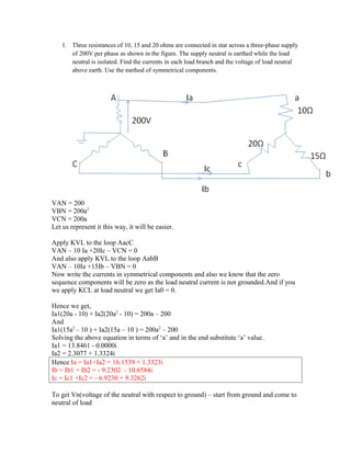
  • 1. 1. Three resistances of 10, 15 and 20 ohms are connected in star across a three-phase supply of 200V per phase as shown in the figure. The supply neutral is earthed while the load neutral is isolated. Find the currents in each load branch and the voltage of load neutral above earth. Use the method of symmetrical components. VAN = 200 VBN = 200a2 VCN = 200a Let us represent it this way, it will be easier. Apply KVL to the loop AacC VAN – 10 Ia +20Ic – VCN = 0 And also apply KVL to the loop AabB VAN – 10Ia +15Ib – VBN = 0 Now write the currents in symmetrical components and also we know that the zero sequence components will be zero as the load neutral current is not grounded.And if you we apply KCL at load neutral we get Ia0 = 0. Hence we get, Ia1(20a - 10) + Ia2(20a2 - 10) = 200a – 200 And Ia1(15a2 – 10 ) + Ia2(15a – 10 ) = 200a2 – 200 Solving the above equation in terms of ‘a’ and in the end substitute ‘a’ value. Ia1 = 13.8461 - 0.0000i Ia2 = 2.3077 + 1.3324i Hence Ia = Ia1+Ia2 = 16.1539 + 1.3323i Ib = Ib1 + Ib2 = - 9.2302 - 10.6584i Ic = Ic1 +Ic2 = - 6.9230 + 9.3262i To get Vn(voltage of the neutral with respect to ground) – start from ground and come to neutral of load
  • 2. Vn = 200 - 10*Ia Vn = 38.4614 -13.3234i Magnitude = 40.7037 2. The voltages at the terminals of a balanced load consisting of three 20 ohm Y-connected resistors are 200(0◦), 10(255.5◦) and 200(151◦) V. Find the line currents from the symmetrical components of the line voltages if the neutral of the load is isolated. What relation exists between the symmetrical components of the line and……….. Solution : Convert star to delta and you get the value of all resistances which are balanced as 60 ohms Iab = 200/60 = 10/3 (00) Ibc = 100(255.50)/60 = 5/3(255.50) Ica = 200(1510)/60 = 10/3(1510) Using symmetrical components resolution formula involving A-1 From this we get Iab1 = 2.7(15.10) Iab2 = 1.03(- 44.530) Ia1 = Iab1 – Ica1 = 4.67(-150) Ia2 = Iab2 – Ica2 = 1.784(-14.50) Ia = Ia1 + Ia2(zero seq. Comp. Currents will not appear in the lines of delta connected or star connected load with neutral isolated) Ia = 6.453(-14.870) Ib1 = a^2Ia1 = 4.67(-1350) Ib2 = aIb2 = 1.784(105.50) Ib = Ib1+Ib2 = 4.105(-156.90) Ic1 = a*Ia1 = 4.67(1050) Ic2 = a^2 Ia2 = 1.784(-134.50) Ic = Ic1+ Ic2 = 4.066(127.40) There the power dissipated in 3 phase 20 ohms resistors is
  • 3. P = Ia^2(20)+ Ib^2(20) + Ic^2(20) = (6.453^2 + 4.1^2+ 4.066^2)(20) P = 1500W