Electromagnetic flowmeters
•Descargar como PPT, PDF•
5 recomendaciones•3,353 vistas

The document discusses various methods for measuring blood flow and volume, which are important for understanding physiological processes. It describes electromagnetic flowmeters, ultrasonic flowmeters including Doppler and transit-time types, and indicator dilution methods using dyes or thermal changes. Electromagnetic flowmeters measure flow based on Faraday's law of induction, while ultrasonic flowmeters rely on transit time differences or the Doppler effect from blood cell movement. Indicator dilution involves injecting a substance and measuring its dispersion over time to calculate flow. Together these provide noninvasive or minimally invasive ways to obtain important blood flow information.

Recomendados
Más contenido relacionado
La actualidad más candente
La actualidad más candente (20)
Destacado
Destacado (20)
Similar a Electromagnetic flowmeters
Similar a Electromagnetic flowmeters (20)
Más de AJAL A J
Más de AJAL A J (20)
Último
Último (20)
Electromagnetic flowmeters
- 2. Characterization of Fluid FlowCharacterization of Fluid Flow Types of Flow RE < 2100 RE >3000 Transitional Turbulent *** Laminar
- 4. Poor Repeatability Means Poor Accuracy Good Accuracy Means Good Repeatability Good Repeatability Does Not Necessarily Mean Good Accuracy
- 5. Differential Pressure FlowmetersDifferential Pressure Flowmeters Flow Measurement Principles ORIFICE PLATE (or FLOW TUBE) VENA CONTRACTA MANOMETER (or DP TRANSMITTER)h Direction of Flow
- 6. Measurement of Flow & Volume of Blood A measurement of paramount importance: concentration of O2 and other nutrients in cells Very difficult to measure Second-class measurement: blood flow and changes in blood volume correlate well with concentration Third-class measurement: blood pressure correlates well with blood flow Fourth class measurement: ECG correlates adequately with blood pressure How to make blood flow / volume measurements? Standard flow meters, such as turbine flow meters, obviously cannot be used! Indicator-dilution method: cont./rapid injection, dye dilution, thermodilution Electromagnetic flowmeters Ultrasonic flowmeters / Doppler flowmeters Plethysmography: Chamber / electric impedance / photoplethysmography
- 7. Indicator Dilution with Continuous Injection Measures flow / cardiac output averaged over several heart beats Fick’s technique: the amount of a substance (O2) taken up by an organ / whole body per unit time is equal to the arterial level of O2 minus the venous level of O2 times the blood flow va CC dtdm C dtdm dt dV F − = ∆ == Blood flow, liters/min (cardiac output) Consumption of O2 (mL/min) Arterial and venous concentration of O2 (mL/L of blood) dtdV dtdm C =∆ Change in [] due to continuously added indicator m to volume V
- 8. Fick’s technique How is dm/dt (O2 consumption) measured? Where and how would we measure Ca and Cv? (Exercise) minL/5 mL/L140L/mL190 minmL/250 ][O][O min)(mL/O 22 2 = − = − = va nconsumptio OutputCardiac
- 9. Indicator Dilution with Rapid Injection A known amount of a substance, such as a dye or radioactive isotope, is injected into the venous blood and the arterial concentration of the indicator is measured through a serious of measurements until the indicator has completely passed through given volume. The cardiac output (blood flow) is amount of indicator injected, divided by average concentration in arterial blood. ∫ = t dttC m F 0 )(
- 10. Indicator – Dilution Curve After the bolus is injected at time A, there is a transportation delay before the concentration begins rising at time B. After the peak is passed, the curve enters an exponential decay region between C and D, which would continue decaying alone the dotted curve to t1 if there were no recirculation. However, recirculation causes a second peak at E before the indicator becomes thoroughly mixed in the blood at F. The dashed curve indicates the rapid recirculation that occurs when there is a hole between the left and right sides of the heart.
- 11. An Example
- 12. Dye Dilution In dye-dilution, a commonly used dye is indocyanine green (cardiogreen), which satisfies the following Inert Safe Measurable though spectrometry Economical Absorption peak is 805 nm, a wavelength at which absorption of blood is independent of oxygenation 50%of the dye is excreted by the kidneys in 10 minutes, so repeat measurements is possible
- 13. Thermodilution The indicator is cold – saline, injected into the right atrium using a catheter Temperature change in the blood is measured in the pulmonary artery using a thermistor The temperature change is inversely proportional to the amount of blood flowing through the pulmonary artery
- 14. Measuring Cardiac Output Several methods of measuring cardiac output In the Fick method, the indicator is O2; consumption is measured by a spirometer. The arterial-venous concentration difference is measure by drawing simples through catheters placed in an artery and in the pulmonary artery. In the dye-dilution method, dye is injected into the pulmonary artery and samples are taken from an artery. In the thermodilution method, cold saline is injected into the right atrium and temperature is measured in the pulmonary artery.
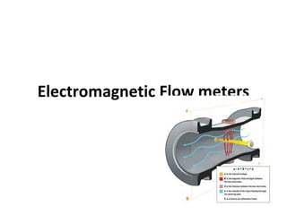
- 15. Electromagnetic Flowmeters Based on Faraday’s law of induction that a conductor that moves through a uniform magnetic field, or a stationary conductor placed in a varying magnetic field generates emf on the conductor: When blood flows in the vessel with velocity u and passes through the magnetic field B, the induced emf e measured at the electrodes is. ∫ ⋅×= L de 0 LBu For uniform B and uniform velocity profile u, the induced emf is e=BLu. Flow can be obtained by multiplying the blood velocity u with the vessel cross section A.
- 16. Electromagnetic Flowmeter Probes • Comes in 1 mm increments for 1 ~ 24 mm diameter blood vessels • Individual probes cost $500 each • Made to fit snuggly to the vessel during diastole • Only used with arteries, not veins, as collapsed veins during diastole lose contact with the electrodes • Needless to say, this is an INVASIVE measurement!!! • A major advantage is that it can measure instantaneous blood flow, not just average flow
- 17. Ultrasonic Flowmeters Based on the principle of measuring the time it takes for an acoustic wave launched from a transducer to bounce off red blood cells and reflect back to the receiver. All UT transducers, whether used for flowmeter or other applications, invariably consists of a piezoelectric material, which generates an acoustic (mechanical) wave when excited by an electrical force (the converse is also true) UT transducers are typically used with a gel that fills the air gaps between the transducer and the object examined
- 18. Near / Far Fields Due to finite diameters, UT transducers produce diffraction patterns, just like an aperture does in optics. This creates near and far fields of the UT transducer, in which the acoustic wave exhibit different properties The near field extends about dnf=D2 /4λ, where D is the transducer diameter and λ is the wavelength. During this region, the beam is mostly cylindrical (with little spreading), however with nonuniform intensity. In the far field, the beam diverges with an angle sinθ=1.2 λ/D, but the intensity uniformly attenuates proportional to the square of the distance from the transducer Higher frequencies and larger transducers should be used for near field operation. Typical operating frequency is 2 ~ 10 MHz.
- 19. UT Flowmeters Zero-crossing detector / LPF Determine direction High acoustic impedance material
- 20. Transit time flowmeters Effective velocity of sound in blood: velocity of sound (c) + velocity of flow of blood averaged along the path of the ultrasound (û) û=1.33ū for laminar flow, û=1.07ū for turbulent flow ū: velocity of blood averaged over the cross sectional area, this is different than û because the UT path is along a single line not over an averaged of cross sectional area Transit time in up/down stream direction: Difference between upstream and downstream directions θcosˆvelocityconduction distance uc D t ± == 2222 cosˆ2 )cosˆ( cosˆ2 c uD uc uD t θ θ θ ≅ − =∆
- 21. Transit Time Flowmeters The quantity ∆T is typically very small and very difficult to measure, particularly in the presence of noise. Therefore phase detection techniques are usually employed rather then measuring actual timing.
- 22. Doppler Flowmeters The Doppler effect describes the change in the frequency of a received signal , with respect to that of the transmitted signal, when it is bounced off of a moving object. Doppler frequency shift c uf f o d θcos2 = Speed of sound in blood (~1500 m/s) Angle between UT beam and flow of blood Speed of blood flow (~150 cm/s) Source signal frequency
- 23. Doppler Flowmeters c u fF s )cos(cos φθ +±=∆
- 24. Problems Associated with Doppler Flowmeters There are two major issues with Doppler flowmeters Unlike what the equations may suggest, obtaining direction information is not easy due to very small changes in frequency shift that when not in baseband, removing the carrier signal without affecting the shift frequency becomes very difficult Also unlike what the equation may suggest, the Doppler shift is not a single frequency, but rather a band of frequencies because • Not all cells are moving at the same velocity (velocity profile is not uniform) • A cell remains within the UT beam for a very short period of time; the obtained signal needs to be gated, creating side lobes in the frequency shift • Acoustic energy traveling within the beam, but at an angle from the bam axis create an effective ∆θ, causing variations in Doppler shift • Tumbling and collision of cells cause various Doppler shifts
- 25. Directional Doppler Directional Doppler borrows the quadrature phase detector technique from radar in determining the speed and direction of an aircraft. Two carrier signals at 90º phase shift are used instead of a single carrier. The +/- phase difference between these carriers after the signal is bounced off of the blood cells indicate the direction, whereas the change in frequency indicate the flowrate
- 26. Directional Doppler (a) Quadrature-phase detector. Sine and cosine signals at the carrier frequency are summed with the RF output before detection. The output C from the cosine channel then leads (or lags) the output S from the sine channel if the flow is away from (or toward) the transducer. (b) Logic circuits route one-shot pulses through the top (or bottom) AND gate when the flow is away from (or toward) the transducer. The differential amplifier provides bi-directional output pulses that are then filtered.
- 27. Electromagnetic Flowmeters • Magnetic flowmeters have been widely used in industry for many years. • Unlike many other types of flowmeters, they offer true noninvasive measurements. • They are easy to install and use to the extent that existing pipes in a process can be turned into meters simply by adding external electrodes and suitable magnets. • They can measure reverse flows and are insensitive to viscosity, density, and flow disturbances. • Electromagnetic flowmeters can rapidly respond to flow changes and they are linear devices for a wide range of measurements. • As in the case of many electric devices, the underlying principle of the electromagnetic flowmeter is Faraday’s law of electromagnetic induction. • The induced voltages in an electromagnetic flowmeter are linearly proportional to the mean velocity of liquids or to the volumetric flow rates.
- 28. • As is the case in many applications, if the pipe walls are made from nonconducting elements, then the induced voltage is independent of the properties of the fluid. • The accuracy of these meters can be as low as 0.25% and, in most applications, an accuracy of 1% is used. • At worst, 5% accuracy is obtained in some difficult applications where impurities of liquids and the contact resistances of the electrodes are inferior as in the case of low-purity sodium liquid solutions. • Faraday’s Law of Induction • This law states that if a conductor of length l (m) is moving with a velocity v (m/s–1 ), perpendicular to a magnetic field of flux density B (Tesla), then the induced voltage e across the ends of conductor can be expressed by: Blve =
- 29. The velocity of the conductor is proportional to the mean flow velocity of the liquid. Hence, the induced voltage becomes: BDve =
- 32. Ultrasonic Flowmeters • There are various types of ultrasonic flowmeters in use for discharge measurement: • (1) Transit time: This is today’s state-of-the-art technology and most widely used type. • This type of ultrasonic flowmeter makes use of the difference in the time for a sonic pulse to travel a fixed distance. • First against the flow and then in the direction of flow. • Transmit time flowmeters are sensitive to suspended solids or air bubbles in the fluid. • (2) Doppler: This type is more popular and less expensive, but is not considered as accurate as the transit time flowmeter. • It makes use of the Doppler frequency shift caused by sound reflected or scattered from suspensions in the flow path and is therefore more complementary than competitive to transit time flowmeters.
- 33. Principle of transit time flowmeters.
- 34. Transit Time Flowmeter • Principle of Operation • The acoustic method of discharge measurement is based on the fact that the propagation velocity of an acoustic wave and the flow velocity are summed vectorially. • This type of flowmeter measures the difference in transit times between two ultrasonic pulses transmitted upstream t21 and downstream t12 across the flow. • If there are no transverse flow components in the conduit, these two transmit times of acoustic pulses are given by:
- 35. Since the transducers are generally used both as transmitters and receivers, the difference in travel time can be determined with the same pair of transducers. Thus, the mean axial velocity along the path is given by:
- 36. Example • The following example shows the demands on the time measurement technique: • Assume a closed conduit with diameter D = 150 mm, angle φ = 60°, flow velocity = 1 m/s, and water temperature =20°C. • This results in transmit times of about 116 s and a time difference ∀ ∆t =t12 – t21 on the order of 78 ns. • To achieve an accuracy of 1% of the corresponding full-scale range, ∆t has to be measured with a resolution of at least 100 ps (1X10⁻¹⁰ s). • Standard time measurement techniques are not able to meet such requirements so that special techniques must be applied. • Digital timers with the state-of-the –art Micro computers will make it possible to measure these time difference.
- 38. Point Velocity Measurement • Pitot Probe Anemometry : Potential Flow Theory & Bernoulli’s Theory . • Thermal Anemometry : Newton’s Law of Cooling. • Laser Anemometry: Doppler Theory.
- 39. Blood Pressure and flow 39
- 40. BMTS 353 40 Blood Flow 12/3/2013 • Blood flow helps to understand basic physiological processes and e.g. the dissolution of a medicine into the body. • Blood flow and changes in blood volume, are usually correlated with concentration of nutrients and other substance in the blood. • Also, Blood Flow measurement reflects the concentration of O2.
- 41. 41 Cont. Blood Flow Normal blood flow velocity 0,5 m/s 1 m/s (Systolic, large vessel)
- 42. 42 Blood Flow Measurement Blood Pressure
- 43. 43 Ultrasonic Doppler Method Blood Pressure • The blood cells in the fluid reflects the ultrasound signal with a shift in the ultrasonic frequency due to its movement. • In the recent years ultrasound contrast agents have been used in order to increase the echoes. c v ff cd 2= f = 2 – 10 MHzc c = 1500 - 1600 m/s (1540 m/s) f = 1,3 – 13 kHzd
- 44. 44 Cont. Ultrasonic Doppler Method Blood Pressure CW DOPPLER PULSED DOPPLER Range ambiguity Low flow cannot be detected No minimum range Simpler hardware Minimum range Accuracy No minimum flow (Maximum flow) x (range) = limited The ultrasound Doppler device can be either a continuous wave or a pulsed Doppler
- 45. 45 Laser Doppler Flowmetry Blood Pressure • The principle of measurement is the same as with ultrasound Doppler. • The laser parameter may have e.g. the following properties: 5 mW He-Ne-laser 632,8 nm wavelength • The method is used for capillary (microvascular) blood flow measurements.
- 46. 46 Plethysmography Method (Strain Gage) Blood Pressure Plethysmography means the methods for recording volume changes of an organ or a body part. • Strain gage is made of silicone rubber tubes, which are filled with conductive liquid (e.g. mercury) whose impedance changes with volume. • Venous occlusion cuff is inflated to 40 – 50 mmHg. In this way there will be the arterial inflow into the limb but no venous outflow.
- 47. 47 Plethysmography Method (Electric-Impedance) Blood Pressure • Different tissues in a body have a different resistivity. Blood is one of the best conductors in a body. • A constant current is applied via skin electrodes. • The change in the impedance is measured. • The accuracy is often poor.
- 48. 48 Plethysmography Method (Photoelectric) Blood Pressure • A beam of IR-light is directed to the part of the tissue which is to be measured for blood flow (e.g. a finger or ear lobe). • The blood flow modulates the attenuated / reflected light which is recorded. • The light that is transmitted / reflected is collected with a photo detector. Poor measure for changes in volume Very sensitive to motion artefacts Method is simple Heart rate is clearly seen
- 49. 49 Blood Flow Measurement Blood Pressure
- 50. 50 Indicator Dilution Methods (Dye Dilution) Blood Pressure • A bolus of indicator, a colored dye (indocyanine green), is rapidly injected in to the vessel. • The concentration is measured in the downstream • The blood is drawn through a colorimetric cuvette and the concentration is measured using the principle of absorption photometry.
- 51. 51 Indicator Dilution Methods (Thermal Dilution) Blood Pressure • A bolus of chilled saline solution is injected into the blood circulation system (right atrium). • This causes decrease in the artery temperature. • Catheter-tip probes are used to measure the change in tempreture.