Sachpazis masonry column with eccentric vertical and wind loading in accordance with en1996 1-1 2005
•
1 recomendación•755 vistas

Masonry column with eccentric vertical and wind loading in accordance with EN1996 1-1 2005

Recomendados
Recomendados
Más contenido relacionado
La actualidad más candente
La actualidad más candente (20)
Destacado
Destacado (20)
Similar a Sachpazis masonry column with eccentric vertical and wind loading in accordance with en1996 1-1 2005
Similar a Sachpazis masonry column with eccentric vertical and wind loading in accordance with en1996 1-1 2005 (20)
Más de Dr.Costas Sachpazis
Más de Dr.Costas Sachpazis (20)
Último
Último (20)
Sachpazis masonry column with eccentric vertical and wind loading in accordance with en1996 1-1 2005
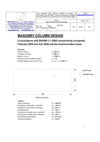
- 1. GEODOMISI Ltd. - Dr. Costas Sachpazis Civil & Geotechnical Engineering Consulting Company for Structural Engineering, Soil Mechanics, Rock Mechanics, Foundation Engineering & Retaining Structures. Tel.: (+30) 210 5238127, 210 5711263 - Fax.:+30 210 5711461 - Mobile: (+30) 6936425722 & (+44) 7585939944, www.geodomisi.com - costas@sachpazis.info Project: Masonry Clay Column Analysis & Design, In accordance with EN1996-1-1:2005 incorporating corrigenda February 2006 and July 2009 and the recommended values. Job Ref. www.geodomisi.com Section Civil & Geotechnical Engineering Sheet no./rev. 1 Calc. by Dr. C. Sachpazis Date 14/09/2014 Chk'd by Date App'd by Date 1 MASONRY COLUMN DESIGN In accordance with EN1996-1-1:2005 incorporating corrigenda February 2006 and July 2009 and the recommended values Geometry Width of column; b = 750 mm Thickness of column; t = 300 mm Height of column; h = 2700 mm Reduction factor for effective height; ρ2 = 1.0 Effective height of column (cl 5.5.1.2); heff = h × ρ2 = 2700 mm Loading Vertical dead load; Gk = 100.0 kN Eccentricity of dead load in x-direction; eGb = 150 mm Eccentricity of dead load in y-direction; eGt = 50 mm Vertical live load; Qk = 7.5 kN Eccentricity of variable load in x-direction; eQb = 150 mm Eccentricity of variable load in y-direction; eQt = 50 mm Characteristic wind loading; Wk = 0.7 kN/m2 Vertical wind loading; Wv = 0.0 kN
- 2. GEODOMISI Ltd. - Dr. Costas Sachpazis Civil & Geotechnical Engineering Consulting Company for Structural Engineering, Soil Mechanics, Rock Mechanics, Foundation Engineering & Retaining Structures. Tel.: (+30) 210 5238127, 210 5711263 - Fax.:+30 210 5711461 - Mobile: (+30) 6936425722 & (+44) 7585939944, www.geodomisi.com - costas@sachpazis.info Project: Masonry Clay Column Analysis & Design, In accordance with EN1996-1-1:2005 incorporating corrigenda February 2006 and July 2009 and the recommended values. Job Ref. www.geodomisi.com Section Civil & Geotechnical Engineering Sheet no./rev. 1 Calc. by Dr. C. Sachpazis Date 14/09/2014 Chk'd by Date App'd by Date 2 Masonry details Masonry type; Clay - Group 1 Mean compressive strength of masonry unit; fb = 10 N/mm2 Density of masonry; γ = 18 kN/m3 Mortar type; M6 - General purpose mortar Compressive strength of masonry mortar; fm = 6 N/mm2 Compressive strength factor - Table 3.3; K = 0.55 Characteristic compressive strength of masonry - eq 3.2 0.7 × fm fk = K × fb 0.3 = 4.719 N/mm2 Characteristic flexural strength of masonry having a plane of failure parallel to the bed joints - cl 3.6.3 fxk1 = 0.1 N/mm2 Partial factors for material strength Category of manufacturing control; Category II Class of execution control; Class 2 Partial factor for masonry in compressive flexure; γMc = 3.00 Slenderness ratio Slenderness ratio minor axis (cl.5.5.2.1); λt = heff / t = 9.00 Slenderness ratio major axis (cl.5.5.2.1); λb = heff / b = 3.60 Maximum slenderness; λ = max(λt, λb) = 9.00 PASS - Slenderness ratio is less than 27 Load combinations derived from Eq 6.10a and Eq 6.10b for lateral loading (utilisation) Combination 1; 1.35 × perm unfav + 1 × perm fav + 1.5 × 0.7 × variable + 1.5 × 0.6 × wind (0.018) Combination 2; 0.85 × 1.35 × perm unfav + 1 × perm fav + 1.5 × variable + 1.5 × 0.6 × wind (0.018) Combination 3; 0.85 × 1.35 × perm unfav + 1 × perm fav + 1.5 × 0.7 × variable + 1.5 × wind (0.029) The following output relates to combination 3 Flexural strength of masonry Self weight at middle of column; Swt = 0.5 × h × t × b × γ = 5.468 kN Design compressive strength of masonry; fd = fk / γMc = 1.573 N/mm2 Design vertical compressive stress; σd = min(γfGh × (Gk + Swt) / (t × b), 0.2 × fd) = 0.315 N/mm2 Design flex masonry strength parallel to bed joints; fxd1 = fxk1 / γMc = 0.033 N/mm2 Apparent design flex strength parallel to bed joints; fxd1,app = fxd1 + σd = 0.348 N/mm2 Column subject to lateral loading about the major axis - Section 6.3 Elastic section modulus of column; Zb = t × b2 / 6 = 28125000 mm3 Moment of resist parallel to bed joints - eq.6.15; MRd1b = fxd1,app × Zb = 9.785 kNm
- 3. GEODOMISI Ltd. - Dr. Costas Sachpazis Civil & Geotechnical Engineering Consulting Company for Structural Engineering, Soil Mechanics, Rock Mechanics, Foundation Engineering & Retaining Structures. Tel.: (+30) 210 5238127, 210 5711263 - Fax.:+30 210 5711461 - Mobile: (+30) 6936425722 & (+44) 7585939944, www.geodomisi.com - costas@sachpazis.info Project: Masonry Clay Column Analysis & Design, In accordance with EN1996-1-1:2005 incorporating corrigenda February 2006 and July 2009 and the recommended values. Job Ref. www.geodomisi.com Section Civil & Geotechnical Engineering Sheet no./rev. 1 Calc. by Dr. C. Sachpazis Date 14/09/2014 Chk'd by Date App'd by Date 3 Bending moment coefficient; α = 0.125 Design moment in column; MEdb = γfWh × α × Wk × h2 × t = 0.287 kNm PASS - Moment resistance greater than design moment in column Column subject to lateral loading about the minor axis - Section 6.3 Elastic section modulus of column; Zt = b × t2 / 6 = 11250000 mm3 Moment of resist parallel to bed joints - eq.6.15; MRd1t = fxd1,app × Zt = 3.914 kNm Bending moment coefficient; α = 0.125 Design moment in column; MEdt = γfWh × α × Wk × h2 × b = 0.718 kNm PASS - Moment resistance greater than design moment in column Load combinations derived from Eq 6.10a and Eq 6.10b for vertical loading (utilisation) Combination 1; 1.35 × perm unfav + 1 × perm fav + 1.5 × 0.7 × variable + 1.5 × 0.6 × wind (0.748) Combination 2; 0.85 × 1.35 × perm unfav + 1 × perm fav + 1.5 × variable + 1.5 × 0.6 × wind (0.662) Combination 3; 0.85 × 1.35 × perm unfav + 1 × perm fav + 1.5 × 0.7 × variable + 1.5 × wind (0.663) The following output relates to combination 1 Flexural strength of masonry Self weight at middle of column; Swt = 0.5 × h × t × b × γ = 5.468 kN Design compressive strength of masonry; fd = fk / γMc = 1.573 N/mm2 Design vertical compressive stress; σd = min(γfGh × (Gk + Swt) / (t × b), 0.2 × fd) = 0.315 N/mm2 Design flex masonry strength parallel to bed joints; fxd1 = fxk1 / γMc = 0.033 N/mm2 Apparent design flex strength parallel to bed joints; fxd1,app = fxd1 + σd = 0.348 N/mm2 Column subject to lateral loading about the major axis - Section 6.3 Elastic section modulus of column; Zb = t × b2 / 6 = 28125000 mm3 Moment of resist parallel to bed joints - eq.6.15; MRd1b = fxd1,app × Zb = 9.785 kNm Bending moment coefficient; α = 0.125 Design moment in column; MEdb = γfWh × α × Wk × h2 × t = 0.172 kNm PASS - Moment resistance greater than design moment in column Column subject to lateral loading about the minor axis - Section 6.3 Elastic section modulus of column; Zt = b × t2 / 6 = 11250000 mm3 Moment of resist parallel to bed joints - eq.6.15; MRd1t = fxd1,app × Zt = 3.914 kNm Bending moment coefficient; α = 0.125 Design moment in column; MEdt = γfWh × α × Wk × h2 × b = 0.431 kNm PASS - Moment resistance greater than design moment in column
- 4. GEODOMISI Ltd. - Dr. Costas Sachpazis Civil & Geotechnical Engineering Consulting Company for Structural Engineering, Soil Mechanics, Rock Mechanics, Foundation Engineering & Retaining Structures. Tel.: (+30) 210 5238127, 210 5711263 - Fax.:+30 210 5711461 - Mobile: (+30) 6936425722 & (+44) 7585939944, www.geodomisi.com - costas@sachpazis.info Project: Masonry Clay Column Analysis & Design, In accordance with EN1996-1-1:2005 incorporating corrigenda February 2006 and July 2009 and the recommended values. Job Ref. www.geodomisi.com Section Civil & Geotechnical Engineering Sheet no./rev. 1 Calc. by Dr. C. Sachpazis Date 14/09/2014 Chk'd by Date App'd by Date 4 Reduction factor for slenderness and eccentricity about the major axis - Section 6.1.2.2 Design bending moment top or bottom of column; Midb = abs(γfGv × Gk × eGb + γfQv × Qk × eQb) = 21.4 kNm Design vertical load at top or bottom of column; Nidb = abs(γfGv × Gk + γfQv × Qk) = 142.9 kN Initial eccentricity - cl.5.5.1.1; einit = heff / 450 = 6.0 mm Conservativley assume moment due to wind load at the top of the column is equal to that at mid height Eccentricity due to horizontal load; ehb = MEdb / Nidb = 1.2 mm Eccentricity at top or bottom of column - eq.6.5; eib = max(Midb / Nidb + ehb + einit, 0.05 × b) = 157.2 mm Reduction factor top or bottom of column - eq.6.4; Φib = max(1 - 2 × eib / b, 0) = 0.581 Ratio of top and middle mnts due to eccentricity; αmdb = 1.0 Design bending moment at middle of column; Mmdb = αmdb × abs(γfGv × Gk × eGb + γfQv × Qk × eQb) = 21.4 kNm Design vertical load at middle of column; Nmdb = γfGv × Gk + γfQv × Qk + γfGv × t × b × γ × h / 2 = 150.3 kN Eccentricity due to horizontal load; ehmb = MEdb / Nmdb = 1.1 mm Eccentricity middle of column due to loads - eq.6.7; emb = Mmdb / Nmdb + ehmb + einit = 149.8 mm Eccentricity at middle of column due to creep; ekb = 0.0 mm Eccentricity at middle of column - eq.6.6; emkb = max(emb + ekb, 0.05 × b) = 149.8 mm From eq.G.2; A1b = 1 - 2 × emkb / b = 0.601 Short term secant modulus of elasticity factor; KE = 1000 Modulus of elasticity - cl.3.7.2; E = KE × fk = 4719 N/mm2 Slenderness - eq.G.4; λb = (heff / b) × √(fk / E) = 0.114 From eq.G.3; ub = (λb - 0.063) / (0.73 - 1.17 × emkb / b) = 0.102 Reduction factor at middle of column - eq.G.1; Φmb = max(A1b × ee -(u × u )/2b b , 0) = 0.597 Reduction factor for slenderness and eccentricity; Φb = min(Φib, Φmb) = 0.581 Reduction factor for slenderness and eccentricity about the minor axis - Section 6.1.2.2 Design bending moment top or bottom of column; Midt = abs(γfGv × Gk × eGt + γfQv × Qk × eQt) = 7.1 kNm Design vertical load at top or bottom of column; Nidt = abs(γfGv × Gk + γfQv × Qk) = 142.9 kN Initial eccentricity - cl.5.5.1.1; einit = heff / 450 = 6.0 mm Conservativley assume moment due to wind load at the top of the column is equal to that at mid height Eccentricity due to horizontal load; eht = MEdt / Nidt = 3.0 mm Eccentricity at top or bottom of column - eq.6.5; eit = max(Midt / Nidt + eht + einit, 0.05 × t) = 59.0 mm Reduction factor top or bottom of column - eq.6.4; Φit = max(1 - 2 × eit / t, 0) = 0.607 Ratio of top and middle mnts due to eccentricity; αmdt = 1.0 Design bending moment at middle of column; Mmdt = αmdt × abs(γfGv × Gk × eGt + γfQv × Qk × eQt) = 7.1 kNm
- 5. GEODOMISI Ltd. - Dr. Costas Sachpazis Civil & Geotechnical Engineering Consulting Company for Structural Engineering, Soil Mechanics, Rock Mechanics, Foundation Engineering & Retaining Structures. Tel.: (+30) 210 5238127, 210 5711263 - Fax.:+30 210 5711461 - Mobile: (+30) 6936425722 & (+44) 7585939944, www.geodomisi.com - costas@sachpazis.info Project: Masonry Clay Column Analysis & Design, In accordance with EN1996-1-1:2005 incorporating corrigenda February 2006 and July 2009 and the recommended values. Job Ref. www.geodomisi.com Section Civil & Geotechnical Engineering Sheet no./rev. 1 Calc. by Dr. C. Sachpazis Date 14/09/2014 Chk'd by Date App'd by Date Design vertical load at middle of column; Nmdt = γfGv × Gk + γfQv × Qk + γfGv × t × b × γ × h / 2 = 5 150.3 kN Eccentricity due to horizontal load; ehmt = MEdt / Nmdt = 2.9 mm Eccentricity middle of column due to loads - eq.6.7; emt = Mmdt / Nmdt + ehmt + einit = 56.4 mm Eccentricity at middle of column due to creep; ekt = 0.0 mm Eccentricity at middle of column - eq.6.6; emkt = max(emt + ekt, 0.05 × t) = 56.4 mm From eq.G.2; A1t = 1 - 2 × emkt / t = 0.624 Short term secant modulus of elasticity factor; KE = 1000 Modulus of elasticity - cl.3.7.2; E = KE × fk = 4719 N/mm2 Slenderness - eq.G.4; λt = (heff / t) × √(fk / E) = 0.285 From eq.G.3; ut = (λt - 0.063) / (0.73 - 1.17 × emkt / t) = 0.435 Reduction factor at middle of column - eq.G.1; Φmt = max(A1t × ee -(u × u )/2t t , 0) = 0.568 Reduction factor for slenderness and eccentricity; Φt = min(Φit, Φmt) = 0.568 Columns subjected to mainly vertical loading - Section 6.1.2 Design value of the vertical load; NEd = max(Nidb, Nmdb, Nidt, Nmdt) = 150.256 kN Design compressive strength of masonry; fd = fk / γMc = 1.573 N/mm2 Vertical resistance of column - eq.6.2; NRd = min(Φt, Φb) × t × b × fd = 200.915 kN PASS - Design vertical resistance exceeds applied design vertical load