CNIC Information System with Pakdata Cf In Pakistan
Pi dcontroller
1. AVR221: Discrete PID controller
Features
• Simple discrete PID controller algorithm
• Supported by all AVR devices 8-bit
• PID function uses 534 bytes of code memory and 877 CPU cycles (IAR - low size
optimization)
Microcontrollers
1 Introduction Application Note
This application note describes a simple implementation of a discrete Proportional-
Integral-Derivative (PID) controller.
When working with applications where control of the system output due to changes
in the reference value or state is needed, implementation of a control algorithm
may be necessary. Examples of such applications are motor control, control of
temperature, pressure, flow rate, speed, force or other variables. The PID controller
can be used to control any measurable variable, as long as this variable can be
affected by manipulating some other process variables.
Many control solutions have been used over the time, but the PID controller has
become the ‘industry standard’ due to its simplicity and good performance.
For further information about the PID controller and its implications the reader
should consult other sources, e.g. PID Controllers by K. J. Astrom & T. Hagglund
(1995).
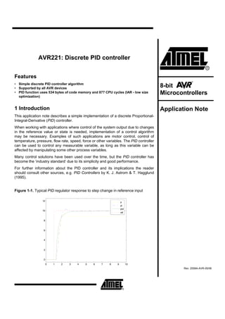
Figure 1-1. Typical PID regulator response to step change in reference input
12 p
pi
pid
10
ref
8
6
4
2
0
0 1 2 3 4 5 6 7 8 9 10
Rev. 2558A-AVR-05/06
2. 2 PID controller
In Figure 2-1 a schematic of a system with a PID controller is shown. The PID
controller compares the measured process value y with a reference setpoint value,
y0. The difference or error, e, is then processed to calculate a new process input, u.
This input will try to adjust the measured process value back to the desired setpoint.
The alternative to a closed loop control scheme such as the PID controller is an open
loop controller. Open loop control (no feedback) is in many cases not satisfactory,
and is often impossible due to the system properties. By adding feedback from the
system output, performance can be improved.
Figure 2-1. Closed Loop System with PID controller
y0 e u y
PID System
-
Unlike simple control algorithms, the PID controller is capable of manipulating the
process inputs based on the history and rate of change of the signal. This gives a
more accurate and stable control method.
The basic idea is that the controller reads the system state by a sensor. Then it
subtracts the measurement from a desired reference to generate the error value. The
error will be managed in three ways, to handle the present, through the proportional
term, recover from the past, using the integral term, and to anticipate the future,
through the derivate term.
Figure 2-2 shows the PID controller schematics, where Tp, Ti, and Td denote the time
constants of the proportional, integral, and derivative terms respectively.
Figure 2-2. PID controller schematic
d
Td
dt
e Kp u
Ti
2 AVR221
2558A-AVR-05/06
3. AVR221
2.1 Proportional term
The proportional term (P) gives a system control input proportional with the error.
Using only P control gives a stationary error in all cases except when the system
control input is zero and the system process value equals the desired value. In Figure
2-3 the stationary error in the system process value appears after a change in the
desired value (ref). Using a too large P term gives an unstable system.
Figure 2-3. Step response P controller
12 p
ref
10
8
6
4
2
0
0 1 2 3 4 5 6 7 8 9 10
2.2 Integral term
The integral term (I) gives an addition from the sum of the previous errors to the
system control input. The summing of the error will continue until the system process
value equals the desired value, and this results in no stationary error when the
reference is stable. The most common use of the I term is normally together with the
P term, called a PI controller. Using only the I term gives slow response and often an
oscillating system. Figure 2-4 shows the step responses to a I and PI controller. As
seen the PI controller response have no stationary error and the I controller response
is very slow.
3
2558A-AVR-05/06
4. Figure 2-4. Step response I and PI controller
12 p
i
pi
10
ref
8
6
4
2
0
0 1 2 3 4 5 6 7 8 9 10
2.3 Derivative term
The derivative term (D) gives an addition from the rate of change in the error to the
system control input. A rapid change in the error will give an addition to the system
control input. This improves the response to a sudden change in the system state or
reference value. The D term is typically used with the P or PI as a PD or PID
controller. A to large D term usually gives an unstable system. Figure 2-5 shows D
and PD controller responses. The response of the PD controller gives a faster rising
system process value than the P controller. Note that the D term essentially behaves
as a highpass filter on the error signal and thus easily introduces instability in a
system and make it more sensitive to noise.
4 AVR221
2558A-AVR-05/06
5. AVR221
Figure 2-5. Step response D and PD controller
12 p
d
pd
10
ref
8
6
4
2
0
0 1 2 3 4 5 6 7 8 9 10
Using all the terms together, as a PID controller usually gives the best performance.
Figure 2-6 compares the P, PI, and PID controllers. PI improves the P by removing
the stationary error, and the PID improves the PI by faster response and no
overshoot.
Figure 2-6. Step response P, PI and PID controller
12 p
pi
pid
10
ref
8
6
4
2
0
0 1 2 3 4 5 6 7 8 9 10
5
2558A-AVR-05/06
6. 2.4 Tuning the parameters
The best way to find the needed PID parameters is from a mathematical model of the
system, parameters can then be calculated to get the desired response. Often a
detailed mathematical description of the system is unavailable, experimental tuning of
the PID parameters has to be performed. Finding the terms for the PID controller can
be a challenging task. Good knowledge about the systems properties and the way the
different terms work is essential. The optimum behavior on a process change or
setpoint change depends on the application at hand. Some processes must not allow
overshoot of the process variable from the setpoint. Other processes must minimize
the energy consumption in reaching the setpoint. Generally, stability is the strongest
requirement. The process must not oscillate for any combinations or setpoints.
Furthermore, the stabilizing effect must appear within certain time limits.
Several methods for tuning the PID loop exist. The choice of method will depend
largely on whether the process can be taken off-line for tuning or not. Ziegler-Nichols
method is a well-known online tuning strategy. The first step in this method is setting
the I and D gains to zero, increasing the P gain until a sustained and stable oscillation
(as close as possible) is obtained on the output. Then the critical gain Kc and the
oscillation period Pc is recorded and the P, I and D values adjusted accordingly using
Table 2-1.
Table 2-1. Ziegler-Nichols parameters
Controller Kp Ti Td
P 0.5 * Kc
PD 0.65 * Kc 0.12 * Pc
PI 0.45 * Kc 0.85 * Pc
PID 0.65 * Kc 0.5 * Pc 0.12 * Pc
Further tuning of the parameters is often necessary to optimize the performance of
the PID controller.
The reader should note there is systems where the PID controller will not work very
well, or will only work on a small area around a given system state. Non-linear
systems can be such, but generally problems often arise with PID control when
systems are unstable and the effect of the input depends on the system state.
2.5 Discrete PID controller
A discrete PID controller will read the error, calculate and output the control input at a
given time interval, at the sample period T . The sample time should be less than the
shortest time constant in the system.
6 AVR221
2558A-AVR-05/06
7. AVR221
2.5.1 Algorithm background
Unlike simple control algorithms, the PID controller is capable of manipulating the
process inputs based on the history and rate of change of the signal. This gives a
more accurate and stable control method.
Figure 2-2 shows the PID controller schematics, where Tp, Ti, and Td denotes the
time constants of the proportional, integral, and derivative terms respectively.
The transfer function of the system in Figure 2-2:
⎛ ⎞
( s ) = H (s ) = K p ⎜1 +
u 1
⎜ T s + Td s ⎟
⎟
e ⎝ i ⎠
This gives u with respect to e in the time domain:
⎛ 1
t
de (t ) ⎞
⎜ e(t ) + ∫ e(σ ) dσ + Td
u (t ) = K p ⎜ ⎟
⎝ Ti 0 dt ⎟ ⎠
Approximating the integral and the derivative terms to get the discrete form, using:
de (t ) e(n ) − e(n − 1)
t n
∫ e(σ )dσ ≈ T ∑ e(k )
0 k =0 dt
≈
T
t = nT
Where n is the discrete step at time t.
This gives the controller:
n
u (n ) = K p e(n ) + K i ∑ e( k ) + K d (e(n ) − e(n − 1))
k =0
Where:
K pT K pTd
Ki = Kd =
Ti T
To avoid that changes in the desired process value makes any unwanted rapid
changes in the control input, the controller is improved by basing the derivative term
on the process value only:
n
u (n ) = K p e(n ) + K i ∑ e( k ) + K d ( y (n ) − y (n − 1))
k =0
7
2558A-AVR-05/06
8. 3 Implementation
A working implementation in C is included with this application note. Full
documentation of the source code and compilation information if found by opening the
‘readme.html” file included with the source code.
Figure 3-1. Block diagram of demo application
pid.c / pid.h
p_factor, i_factor
pid
main() Init_PID()
LAST_PROCESS_VALUE
d_factor SUM_ERROR
P_FACTOR
I_FACTOR
setPoint, processValue D_FACTOR
PID_timer MAX_ERROR
PID()
MAX_SUM_ERROR
control input
In Figure 3-1 a simplified block diagram of the demo application is shown.
The PID controller uses a struct to store its status and parameters. This struct is
initialized in main, and only a pointer to it is passed to the Init_PID() and PID()
functions.
The PID() function must be called for each time interval T, this is done by a timer
who sets the PID_timer flag when the time interval has passed. When the PID_timer
flag is set the main routine reads the desired process value (setPoint) and system
process value, calls PID() and outputs the result to the control input.
To increase accuracy the p_factor, i_factor and d_factor are scaled with a factor
1:128. The result of the PID algorithm is later scaled back by dividing by 128. The
value 128 is used to allow for optimizing in the compiler.
PFactor = 128K p
Furthermore the effect of the IFactor and DFactor will depend on the sample time T .
T
IFactor = 128 K p
Ti
T
DFactor = 128 K p d
T
3.1 Integral windup
When the process input, u, reaches a high enough value, it is limited in some way.
Either by the numeric range internally in the PID controller, the output range of the
controller or constraints in amplifiers or the process itself. This will happen if there is a
large enough difference in the measured process value and the reference setpoint
value, typically because the process has a larger disturbance / load than the system
is capable of handling.
8 AVR221
2558A-AVR-05/06
9. AVR221
If the controller uses an integral term, this situation can be a problematic. The integral
term will sum up as long as the situation last, and when the larger disturbance / load
disappear, the PID controller will overcompensate the process input until the integral
sum is back to normal.
This problem can be avoided in several ways. In this implementation the maximum
integral sum is limited by not allowing it to become larger than MAX_I_TERM. The
correct size of the MAX_I_TERM will depend on the system and sample time used.
4 Further development
The PID controller presented here is a simplified example. The controller should work
fine, but it might be necessary to make the controller even more robust (limit
runaway/overflow) in certain applications. Adding saturation correction on the integral
term, basing the proportional term on only the system process value can be
necessary.
In the calculating of IFactor and DFactor the sample time T is a part of the equation.
If the sample time T used is much smaller or larger than 1 second, accuracy for
either IFactor or DFactor will be poor. Consider rewriting the PID algorithm and
scaling so accuracy for the integral and derivate term is kept.
5 Literature references
K. J. Astrom & T. Hagglund, 1995: PID Controllers: Theory, Design, and Tuning.
International Society for Measurement and Con.
9
2558A-AVR-05/06