Hyundai HD65, HD72, HD78 Electrical Troubleshooting Manual
•
69 recomendaciones•45,404 vistas

Hyundai HD65, HD72, HD78 Electrical Troubleshooting Manual

Recomendados
Más contenido relacionado
La actualidad más candente
La actualidad más candente (20)
Similar a Hyundai HD65, HD72, HD78 Electrical Troubleshooting Manual
Similar a Hyundai HD65, HD72, HD78 Electrical Troubleshooting Manual (20)
Más de Viktor
Último
Último (20)
Hyundai HD65, HD72, HD78 Electrical Troubleshooting Manual
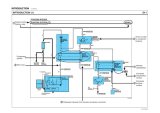
- 1. INTRODUCTION E103F6A0 GI-1INTRODUCTION (1) STARTING SYSTEM (1) STARTING SYSTEM System name/ System code Component symbol Wire color SD360-1 E2RG360A START SOLENOID START MOTOR BATTERY BATTERY GROUND BODY GROUND MOTOR ENGINE LEVER MAGNETIC OVERRUNNING CLUTCH PINION GEAR FLYWHEEL WBB P R N D L 2 TRANSAXLE RANGE SWITCH ETACM IGNITION SWITCH ON ST ACC LOCK AM 6 R R M11 M11 E27 E27 8 C34 7 C34 5 2 3 M19 M19 3 M70-16 M1951 4 51 START RELAY E/R RELAY & FUSE BOX BURGLAR ALARM RELAY I/P JUNCTION BOX 4 FUSIBLE LINK(IGN) 30A 1 EE01 L B G10 1 EM01 1 EM03 PHOTO 08 PHOTO 01 PHOTO 08 PHOTO 08 PHOTO 09 PHOTO 04 PHOTO 06 PHOTO 07 PHOTO 05 PHOTO 03 PHOTO 02 W W G R R EM025 MC027 P P W Gr Gr B B B/Y See Ground Distribution Distinguish harness from harness connection connector3 Picture number for component locations 4 1 Harness classification 7 Connector classification number Connector terminal number 8 5 6 EVTGI70001L
- 2. INTRODUCTION GI-2INTRODUCTION (2) Connector configurations (components) Explanation of connector code 2 M05 a : Connector manufacturer b : Terminal series number c : The number of connector terminals d : Connector distinguishing e : Connector color abbreviations KET_090II_04F_W 1 a b c d e 234 B (Black) Br (Brown) G (Green) Gr (Gray) L (Blue) R (Red) W (White) Y (Yellow) Female Pin : F Male Pin : M M05 KET_090II_04F_W KET_090II_10M_W AMP_PLM2_02F_B KET_090II_06M_W KUM_AR_04F_W KET_090II_10F_W M06 M11 M13 BLANK BLANK M81M67 *234 1 2 * * 4 5 6 8 9 10 1234 134 5678 12 1 2 3 4 5 6 Unused pin * ** STARTING SYSTEM (2) STARTING SYSTEM SD360-2 E2RG360B EVTGI70002L
- 3. INTRODUCTION GI-3INTRODUCTION (3) Pages by system/ Name of Schematic diagram Each page is consisted of circuits by system. This schematic diagram includes the path of electricity flow, connection condition for each switch, and the function of other relevant circuits at once. It is applicable to real service work. 1 Connector configurations (connection between harnesses) The connector figure of components in the schematic diagram by system is indicated on the last page of schematic diagram. It shows the front of the connector on the harness side when not to the harness connector. The terminal number on each connector can be obtained by following the pattern used in 5 connector view and numbering order. Unused terminals are marked with an asterisk ( ). When connecting the harness with connector between harnesses, it shows female and male connectors and indicates them on the connector configurations group. To find the components easily, a component locations diagram is indicated with "PHOTO NO" on the lower portion of the component name. To make it easy to distinguish connectors, the connector in the picture is indicated being installed in the vehicle. Circuits by system depends upon part number and are indicated on schematic diagram index. 10 9 8 7 6 5 4 3 2122 12 17181920 16 15 1314 12 11 109876543 21 22 1 2 17 18 19 20161513 141211 EM02 PHOTO 03 3 2 1 6 5 4 1 2 3 4 5 6 3 2 1 6 5 4 1 2 3 4 5 6 Connector configuration (components)2 3 Component locations4 CONNECTOR VIEW AND NUMBERING ORDER5 It is very important to understand relevant circuits exactly before troubleshooting diagnosis. Male It is not the shape of the connector housing, but the connector pin that distinguishes between male or female connectors. When numbering female and male connectors, refer to the numbering order in the following table. Some connectors may not follow this method of numbering order. For individual detailed numbering, refer to the CONNECTOR CONFIGURATIONS. Female Remarks Locking point Housing Pin Locking point Pin Housing Numbered in order from upper right to lower left Numbered in order from upper left to lower right NOTE UNLESS OTHERWISE STATED, ALL CONNECTOR VIEWS ARE FROM THE TERMINAL SIDE OF THE CONNECTOR. * EVTGI70003L
- 4. INTRODUCTION GI-4INTRODUCTION (4) WIRE COLOR ABBREVIATIONS The following abbreviations are used to identify wire colors in the circuit schematics. 6 A connector identification symbol consists of a wiring harness location classification symbol corresponding to a wiring harness location and number corresponding to the connector. These connector locations can be found in the HARNESS LAYOUTS. HARNESS CLASSIFICATION Electrical wiring connectors are classified according to the wiring parts in the Harness Layouts. 7 CONNECTOR IDENTIFICATION8 It depends on vehicles, it is necessary to check the harness name symbol on the harness layouts for detailed symbol. Black Brown Green Gray Blue Light Green Tan Orange Pink Red White Yellow Purple Light Blue the color of background the color of stripe For example: For example: For example: O P R W Y Pp LI B Br G Gr L Lg T Symbol Color of wire Symbol Color of wire E 10 -1 NOTE Connectors which connect each wiring harness are represented by the following symbols. JUNCTION BLOCK IDENTIFICATION A junction block identification symbol consists of a wiring harness location classification symbol corresponding to a wiring harness location and number corresponding to the connector in the junction block. M R 01 I/P- A Symbol indicating wiring harness (Engine wiring harness) Number corresponding to main connector (Serial Number) Number corresponding to sub-connector (Serial Number) Number corresponding to main connector (Serial Number) Rear wiring harness Main wiring harness Abbreviation of the word "Passenger compartment junction block" Connector name Y / B : Black stripe with yellow ground (2 colors)* Engine harness Main, Floor, Floor center, Roof harness Chassis, Side marker, EXH M/V harness Air con, A.B.S harness Door harness E A D LocationHarness nameSymbol C M Engine compartment Passenger compartment, Floor, Roof Under crash pad and Floor Door Chassis compartment EVTGI70004L
- 5. INTRODUCTION GI-5INTRODUCTION (5) HARNESS LAYOUTS Harness layouts show the routing of the major wiring harnesses, the in-line connectors and the splices between the major harnesses. These layouts will make electrical troubleshooting easier. MM02 G14 G12 M26 M31 M34 M35 M32 M22 M21 M23 M25-1,2,3 MM01 MM03 M33 SM01 SM02 M36 MM04 M41 VIEW 'B' VIEW 'A' M30 Z03M29 M15 M13 M19-2 SM06 SM08 SM07 M37 M02 M03-1,2 MI04 MI06 MI03 MI05 M20 M11M16 Z01 G11 M14 MC06 MC05 MC04 M09-3 M09-1,2 MI01 Z02 Passenger Compartment Junction Block (I/P-E,F,G,H,J) EVTGI70005L
- 6. SYMBOLS EBB531CD GI-6SYMBOLS (1) C O M P O N E N T G R O U N D S P L I C E S C O N N E C T O R W I R E Symbol Sec- tion Sec- tion Sec- tion Sec- tion A solid line means the entire component is shown. Shows the name of each connector on the component location index for reference. Indicates the number of corresponding terminal. (Only relevant terminal on the corresponding schematic diagram). The dashed-line means each of two wires connect with same connector(E35) A broken line indicates only part of the component is shown. Meaning Symbol Meaning Symbol Meaning Symbol Meaning STOP LAMP SWITCH PHOTO 03 Female connector Male connector 10 M05-2 E35 R Y/L R Y/L 13 B A R Y/R A From C52 To MC02 G G G L L D I O D E TR C B E F U S E G E N E R A L C O M P O N E N T S Y M B O L L A M P Diode Led diode Zener diode Switch (1 contact point) Heater NPN PNP NPN PNP Power supplied at all times. Control battery power at all times Double filament Single filament Name Capacity HOT IN ON FUSE 10 10A DASH FUSE BOX C B E S H I E L D W I R E J O I N T C O N N E C T O R S L O W B L O W P O W E R G06 This means the connector connects directly to the component. This indicates a screw terminal on the component. This means power is supplied with the ignition on position. Identification Current rating This means the short bar connects to other fuses. This indicates the connector connects to a lead (pigtail), wired directly to the com- ponent. Automatic Transaxle Manual Transaxle This symbol means the end of the wire is attached to a metal part of the vehicle. This ground symbol (dot and 3 lines overlapping the com- ponent) means the housing of the component is attached to a metal part of the vehicle. The name of the component appears next to its upper right corner. Shows the number of pictures for component location. Splices are numbered and shown as a dot with circle. The exact location and con- nection of these splices may vary among vehicles. Wire choices for options or different models are labeled and shown with a "choice" bracket like this. Name of Circuit A wire connects to another circuit. The wire is shown again on that circuit which the arrow is pointing. Current path is continued on the same page or another page.The arrow shows the direction of current flow. You should look for the "A" in the marked position. A wavy line means the wire is broken but is to be continued. Wire insulation is yellow with a red strip. C O N N E C T O R This represents RFI (Radio Frequency Interference) Shielding around a wire. The shielding is always connected to ground. This is a connector showing the joining wires. These switches move together: a dashed line shows a mechanical connection between them. F/FOG FUSE 15A E/R FUSE & RELAY BOX HOT AT ALL TIMES G06 EVTGI70006L
- 7. SYMBOLS GI-7SYMBOLS (2) Sec- tion Sec- tion G E N E R A L C O M P O N E N T S S Y M B O L G E N E R A L C O M P O N E N T S S Y M B O L R E L A Y Solenoid Injector Normally open contact Motor Battery Condenser Speaker Horn, Buzzer, Siren, Chime Bell Sensor Sender M + - This is a relay shown with no current flowing through its coil. When a current flows through coil, contact will toggle. Diode interior relay Resistance interior relay Symbol Meaning Symbol Meaning EVTGI70007L
- 8. TROUBLESHOOTING INSTRUCTIONS E69D8CAB GI-8TROUBLESHOOTING INSTRUCTIONS (1) TROUBLESHOOTING INSTRUCTIONS TROUBLESHOOTING PROCEDURES TROUBLESHOOTING EQUIPMENT CAUTION The following five-step troubleshooting procedure is recommended. Turn on all the components in the problem circuit to check the accuracy of the customer's complaints. Note the symptoms. Do not begin disassembly or testing until you have narrowed down the probable causes. 1. Verify the customer's complaints Use a test lamp or a voltmeter on circuits without solidstate units and use a test lamp to check for voltage. A test lamp is made up of a 12-volt light bulb with a pair of leads attached. After grounding one lead, touch the other lead to various points along the circuit where voltage should be present. When the bulb goes on, there is voltage at the point being tested. SELF-POWERED TEST LAMP AND OHMMETER Use a self-powered test lamp or an ohmmeter to check for continuity. The ohmmeter shows how much resistance there is between two points along a circuit. Low resistance means good continuity. A number of circuits include solid-state modules, such as the Engine Control Module(ECM), used with computer command control injection. Voltage in these circuits should be tested only with a 10-megaohm or higher impedance digital multimeter. Never use a test lamp on circuits that contain solid state modules. Damage to the modules may result. VOLTMETER AND TEST LAMP Make a circuit test to check the diagnosis you made in step 2. Remember that a logical, simple procedure is the key to efficient troubleshooting. Narrow down the probable causes using the troubleshooting hints and system diagnosis charts. Test for the most likely cause of failure first. Try to make tests at points that are easily accessible. 3. Inspect the circuit/ component with the problem isolated Once the problem is found, make the necessary repairs. 4. Repair the problem Repeat the system check to be sure you have repaired the problem. If the problem was a blown fuse, be sure to test all of the circuits on that fuse. 5. Make sure the circuit works Locate the schematic for the problem circuit. Determine how the circuit is supposed to work by tracing the current paths from the power source through the system components to ground. If you do not understand how the circuit should work, read the circuit operation text. Also check other circuits that share with the problem circuit. The name of circuits that share the same fuse, ground, or switch, for example, are referred to on each diagram. Try to operate any shared circuits you did not check in step 1. If the shared circuit works, the shared wiring is okay, and the cause must be within the wiring used only by the problem circuit. If several circuits fail at the same time, the fuse or ground is a likely cause. 2. Read and analyze the schematic diagram TEST LAMP A voltmeter can be used in place of a test lamp. While a test lamp shows whether the voltage is present or not, a voltmeter indicates how much voltage is present. EVTGI70008L
- 9. TROUBLESHOOTING INSTRUCTIONS GI-9TROUBLESHOOTING INSTRUCTIONS (2) Never use a self-powered test lamp on circuits that contain solid state modules. Damage to these modules may result. An ohmmeter can be used in place of a self-powered test lamp. The ohmmeter shows how much resistance there is between two points along a circuit. Low resistance means good continuity. Circuits which include any solid-state devices should be tested only with a 10-megaohm or higher impedance digital multimeter. When measuring resistance with a digital multimeter, the battery negative terminal should be disconnected. Otherwise, there may be incorrect readings. Diodes and solid-state devices in a circuit can make an ohmmeter give a false reading. To find out if a component is affecting a measurement, take one reading, reverse the leads and take a second reading. If different the solid-state device is affecting the measurement. Use a jumper wire with a fuse to by-pass an open circuit. A jumper wire is made up of an in-line fuse holder connected to a set of test leads. This tool is available with small clamp connectors providing adaption to most con- nectors without damage. CAUTION Do not use a fuse with a higher rating than the specified fuse that protects the circuit being tested. Do not use this tool in any situation to substitute an input or output at the solid-state control module, such as ECM, TCM, etc. CAUTION JUMPER WIRE WITH FUSE A short finder is available to locate a short to ground. The short finder creates a pulsing magnetic field in the shorted circuit and shows you the location of the short through body trim or sheet metal. SHORT FINDER SELF- POWERED TEST LAMP 5A TROUBLESHOOTING TEST This test measures voltage in a circuit. When testing for voltage at a con- nector, you do not have to separate the two halves of the connector. lnstead, probe the connector from the back(backprobe). Always check both sides of the connector because dirt and corrosion between its contact surfaces can cause electrical problems. A. Connect one lead of a test lamp or voltmeter to a ground. If you are using a voltmeter, be sure it is the voltmeter's negative test lead you have con- nected to ground. B. Connect the other lead of the test lamp or voltmeter to a selected test point(connector or terminal). C. If the test lamp glows, there is voltage present. If you are using a voltmeter, note the voltage reading. A loss of more than 1 volt from specification indicates a problem. 1. TESTING FOR VOLTAGE EVTGI70009L
- 10. TROUBLESHOOTING INSTRUCTIONS GI-10TROUBLESHOOTING INSTRUCTIONS (3) A. Disconnect the battery negative terminal. B. Connect one lead of a self-powered test lamp or ohmmeter to one end of the part of the circuit you wish to test. If you are using an ohmmeter, hold the leads together and adjust the ohmmeter to read zero ohms. C. Connect the other lead to the other end. D. If the self-power test lamp glows, there is continuity. If you are using an ohmmeter, low or zero resistance means good continuity. 2. TESTING FOR CONTINUITY A. Disconnect the battery negative terminal. B. Connect one lead of a self-powered test lamp or an ohmmeter to the fuse terminal on the load side. C. Connect the other lead to a ground. D. Beginning near the fuse block move the harness from side to side. Continue this proceedure(about six inches apart) while watching the self-powered test lamp or ohmmeter. E. When the self-powered test lamp glows, or ohmmeter registers, there is a short to a ground in the wiring near that point. 3. TESTING FOR SHORT TO GROUNDHOT AT ALL TIMES DASH FUSE BOX SWITCH SOLENOID TEST LAMP OR VOLTMETER RON OFF G 4 M11 SELF- POWERED TEST LAMP OR OHMMETER STOP LAMP SWITCH SOLENOID G SELF-POWERED TEST LAMP OR VOLTMETER Short to ground Battery disconnected FUSE BOX (Fuse removed) Load disconnected SWITCH 4 M11 1 M11 R EVTGI70010L
- 11. TROUBLESHOOTING INSTRUCTIONS GI-11TROUBLESHOOTING INSTRUCTIONS (4) A. Remove the blown fuse. Leave the battery connected. B. Connect the short finder across the fuse terminals. C. Close all switches in series in the circuit that is being testing. D. Turn on the short circuit locator. It sends pulses of current to the short. This creates a pulsing magnetic field around the wiring between the fuse box and the short. E. Beginning at the fuse box, slowly move the short finder along the circuit wiring. The meter will show current pulses through sheet metal and body trim. As long as the meter is between the fuse and the short, the needle will move with each current pulse. Once the meter is moved past the point of the short, the needle will stop moving. Check around this area to locate the cause of the short circuit. 4. TESTING FOR A SHORT WITH A SHORT FINDER SHORT FINDER FUSE BOX (Fuse removed) R 4 M11 SWITCH SOLENOID G Short to ground Battery disconnected M111 METER Move meter along wire Needle stops moving here Pulsing magnetic field Pulsing magnetic field EVTGI70011L
- 12. FUSE & RELAY INFORMATION EBF7DCCF SD100-1FUSE & RELAY INFORMATION (1) <D4DD> <D4AF/D4AL> USE THE DESIGNATED FUSE ONLY FUSE 1 15A FUSE 2 5A FUSE 3 10A FUSE 4 10A FUSE 5 15A FUSE 6 5A FUSE 7 5A FUSE 8 10A FUSE 9 10A FUSE 10 15A FUSE 11 10A FUSE 12 10A FUSE 14 15A FUSE 15 10A FUSE 16 20A FUSE 17 10A FUSE 18 15A FUSE 19 10A FUSE 20 20A FUSE 21 20A FUSE 23 10A FUSE 24 15A FUSE 25 10A FUSE 26 10A FUSE 27 10A FUSE 28 10A FUSE 29 10A FUSE 30 10A FUSE 31 10A FUSE 32 5A FUSE 33 20A FUSE 34 15A FUSE 35 10A FUSE 36 15A FUSE 1 15A FUSE 2 5A FUSE 3 10A FUSE 4 10A FUSE 5 15A FUSE 6 5A FUSE 7 5A FUSE 9 15A FUSE 11 10A FUSE 12 10A FUSE 13 20A FUSE 14 10A FUSE 15 10A FUSE 16 10A FUSE 17 10A FUSE 18 15A FUSE 19 15A FUSE 23 10A FUSE 24 15A FUSE 25 10A FUSE 26 10A FUSE 27 10A FUSE 28 10A FUSE 29 10A FUSE 30 10A FUSE 31 10A FUSE 33 15A FUSE 34 15A FUSE 36 15A FUSE BOX EVTSD7100AL
- 13. FUSE & RELAY INFORMATION SD100-2FUSE & RELAY INFORMATION (2) USE THE DESIGNATED FUSE ONLY CIRCUIT Working lamp switch Head lamp leveling actuator(D4AF/D4AL), Head lamp leveling switch(D4AF/D4AL), Head lamp relay(High/Low) Mode switch, Intake switch, A/C switch, Evaporator sensor, Blower relay, Condenser fan relay Wiper motor, Washer motor, Wiper relay(High/Low) ABS control module PTO relay, Dump relay, PTO control switch Main ECM(D4DD) Neutral switch(D4DD) Power window relay(D4AF/D4AL) Cab tilting switch, Flasher unit Power door lock relay, Power door unlock relay ABS relay box(Fail safe relay) Engine ECM relay(D4DD), Main ECM(D4DD) Fuel heater relay(D4DD) ETACM(D4AF/D4AL), Start solenoid, Sub start switch, Main ECM(D4DD) Head lamp LH(Lo) Head lamp RH(Lo) Head lamp LH(Hi), Instrument cluster(High-beam indicator) Head lamp RH(Hi) Hazard switch, Defogger switch, A/C switch, Front fog lamp switch, License lamp, Rear combination lamp LH, Rear fog lamp switch(D4AF/D4AL), Rear marker lamp LH(D4AF/D4AL), Front outside marker lamp(D4AF/D4AL), Cigarette lighter(D4DD) Position lamp RH, Front room lamp, Endout marker lamp, Rear combination lamp RH, Rear marker lamp RH(D4AF/D4AL), Rear outside marker lamp(D4AF/D4AL) Front fog lamp relay Engine PTO cab in switch(D4DD), Accelerator pedal sensor(D4DD), Exhaust brake clutch pedal position switch(D4DD), Stop lamp switch(D4DD), Multifunction switch(Exhaust brake switch)(D4DD), Idle up/down switch(D4DD) Blower relay Not used(D4DD) Cigarette lighter, Audio, Instrument cluster(Clock) Neutral switch(D4AF/D4AL), Main ECM(D4DD), Exhaust brake relay(D4DD) Cold start switch(D4AF/D4AL), Exhaust brake clutch pedal position switch(D4AF/D4AL), Tachograph, High speed warning device(D4AF/D4AL), High speed warning buzzer(D4AF/D4AL), Glow relay(D4DD), Fuel heater relay(D4DD), Exhaust brake relay(D4DD), ABS relay 15A 5A 10A 10A 15A 5A 5A 10A(D4DD) 15A(D4AF/D4AL) 10A(D4DD) 15A(D4DD) 20A 10A(D4AF/D4AL) 15A(D4DD) 10A 10A(D4AF/D4AL) 20A(D4DD) 10A 15A 15A(D4AF/D4AL) 10A(D4DD) 20A(D4DD) 20A(D4DD) 15A 10A 10A 10A 10A 10A 15A(D4AF/D4AL) 20A(D4DD) 15A 10A(D4DD) 15A WORKING LAMP HEAD LP (RELAY) A/CON D4AF/D4AL(COLD START), D4DD(TACHOGRAPH, GLOW, ABS), EXH. BRAKE WIPER WASHER A. B. S (ECU) P. T. O (OPT) D4DD(ENG ECU) D4AF/D4AL(SUB START), D4DD(ENG ECU, EXH BRAKE) D4DD(SUB START) D4AF/D4AL(OVERHEAT BZ), REVERSE LP, SPD SENSOR D4AF/D4AL(ALTR (R)), CLUSTER, ETACS D4AF/D4AL(P/WINDOW) D4AF/D4AL(STOP LP, HORN) D4DD(HEAT'G MIRROR) HAZARD, T/SIG LP, CAB TILT'G D4AF/D4AL(RR FOG LAMP) D4DD(P/WINDOW) C/DOOR LOCK A. B. S (VALVE) D4AF/D4AL(HEAT'G MIRROR) D4DD(STOP LP, HORN, DIAG CONN) D4DD(ENG ECU) D4DD(FUEL HEATER) D4DD(ETACS, TACHOGRAPH), AUDIO, ROOM LP, CLOCK START MOTOR HEAD LP (DIM. LH) HEAD LP (DIM. RH) HEAD LP (MAIN. LH) HEAD LP (MAIN. RH) FOG LAMP D4AF/D4AL(CONDENSER FAN) D4DD(A/C COMP, CONDENSER) HEATER BLOWER D4DD(ETACS) CIGAR, AUDIO, CLOCK 1 2 3 4 5 6 7 8 10 13 15 17 18 20 21 24 25 26 27 28 31 34 35 36 9 Overheat buzzer relay(D4AF/D4AL), Vehicle speed sensor, Back-up lamp switch, Water separator sensor(D4DD), Generator(D4DD)11 Instrument cluster(Indicator), ETACM, Generator(D4AF/D4AL)12 Data link connector(D4AF/D4AL), Stop lamp switch(D4AF/D4AL), Horn(D4AF/D4AL), Outside mirror defogger relay(D4DD)14 Rear fog lamp relay(D4AF/D4AL), Rear fog indicator relay(D4AF/D4AL), Power window relay(D4DD)16 Outside mirror defogger relay(D4AF/D4AL), Data link connector(D4DD), Stop lamp switch(D4DD), Horn(D4DD), Horn relay(D4DD)19 Instrument cluster(Clock), ETACM, Audio, Front room lamp, Rear room lamp, Tachograph23 Condenser fan relay, A/C relay33 29 TAIL LP (LH) 10A 30 TAIL LP (RH) 10A 32 D4DD(ENG ECU) 5A(D4DD) Fuse Description (A) Circuit protected 10A 10A 10A EVTSD7100BL
- 14. FUSE & RELAY INFORMATION SD100-3FUSE & RELAY INFORMATION (3) USE THE DESIGNATED FUSE ONLY FUSIBLE LINK BOX BODY 40A ALTERNATOR 60A ABS 30A A/CON 30A IGN SW 30A ABS relay box(Pump motor relay) Fuse box(Fuse 33, Fuse 34) Ignition switch Relay box(Head lamp relay (High/Low), Tail lamp relay), Fuse box(D4AF/D4AL(Fuse 13~19), D4DD(Fuse 15~21), Fuse 31) Generator 30A 30A 30A 60A Description (A) Circuit protected ABS A/CON IGN SW ALTERNATOR 40ABODY CIRCUIT EVTSD7100CL
- 15. FUSE & RELAY INFORMATION SD100-4FUSE & RELAY INFORMATION (4) USE THE DESIGNATED FUSE ONLY M01 FRONT FOG LAMP RELAY M15 ABS RELAY M05 POWER DOOR LOCK RELAY M06 POWER DOOR UNLOCK RELAY M07 OUTSIDE MIRROR DEFOGGER RELAY M08 PTO RELAY M09 DUMP RELAY M93 EXHAUST BRAKE RELAY M11 WIPER RELAY (HIGH) M12 WIPER RELAY (LOW) M13 HEAD LAMP RELAY (HIGH) M04 POWER WINDOW RELAY M14 HEAD LAMP RELAY (LOW) M90 FUEL HEATER RELAY M91 ENGINE ECM RELAY M02 TAIL LAMP RELAY M01 FRONT FOG LAMP RELAY M16 REAR FOG LAMP RELAY M97 OVERHEAT BUZZER RELAY M15 ABS RELAY M88 HORN RELAY M05 POWER DOOR LOCK RELAY M06 POWER DOOR UNLOCK RELAY M07 OUTSIDE MIRROR DEFOGGER RELAY M08 PTO RELAY M09 DUMP RELAY M11 WIPER RELAY (HIGH) M12 WIPER RELAY (LOW) M13 HEAD LAMP RELAY (HIGH) M04 POWER WINDOW RELAY M14 HEAD LAMP RELAY (LOW) M86 REAR FOG INDICATOR RELAY M02 TAIL LAMP RELAY M94 GLOW RELAY * 1 24 5 * 1 24 5 * 1 24 5 * 1 24 5 * 1 24 5 * 1 24 5 <D4DD> <D4AF/D4AL> 1 2 3 5 * 1 2 4 3 5 1 2 4 3 5 1 2 3 5 * 1 2 3 5 * 1 4 3 5 * 1 4 3 5 * 1 2 4 3 5 1 2 4 3 5 1 2 4 3 5 1 2 3 5 *1 4 3 5 * 1 4 3 5 * 1 4 3 5 * 1 4 3 5 * 1 2 3 5 * 1 2 3 5 * 1 2 3 5 * 1 2 3 5 * 1 234 5 1 234 5 * 1 24 5 * 1 24 5 * 1 24 5 * 1 24 5 * 1 24 5 1 234 5 1 234 5 RELAY BOX EVTSD7100DL
- 16. POWER DISTRIBUTION EA007534 SD110-1POWER DISTRIBUTION (1) 1CC031 C131 CC012 3.0Y 3.0G 8.0W 3.0G BATTERY GROUND + - 1 FUSIBLE LINK BOX BATTERY + - BATTERY E17 ABS RELAY BOX START MOTOR GENE- RATOR 1 ABS FUSIBLE LINK 30A ALTERNATOR FUSIBLE LINK 60A A/CON FUSIBLE LINK 30A BODY FUSIBLE LINK 40A FUSE 34 15A FUSE 23 10A C34-21 3.0L3.0R HEAD LAMP RELAY (LOW) MC0363 M145 1.25G 3.0L 1.25O 2.0L 2.0L 3.0L 2.0L 0.5L 3.0R 1.25G/O 3.0R 3.0R CC022 M141 HEAD LAMP RELAY (HIGH) TAIL LAMP RELAY M135 M131 RELAY BOX 5 M02 4 M02 2 1 See Tail, Parking & License Lamps (SD928-1)(SD928-2) 2.0R FUSE BOX FUSE 15 10A A To IGN SW Fusible Link 30A (SD110-2) 2 8.0L 8.0L 8.0W EC031 5.0W 8.0L FUSE 33 15A(D4AF/D4AL) 20A(D4DD) FUSE 26 10A FUSE 25 10A FUSE 28 10A FUSE 27 10A FUSE 30 10A FUSE 29 10A FUSE 16 20A FUSE 17 10A FUSE 18 15A FUSE 19 10A FUSE 20 20A FUSE 21 20A FUSE 13 20A FUSE 14 10A FUSE 15 10A FUSE 16 10A FUSE 17 10A FUSE 18 15A FUSE 19 15A FUSE 31 10A D4DD D4AF/D4AL See Passenger Compartment Fuse Details (SD120-7) See Passenger Compartment Fuse Details (SD120-5) See Passenger Compartment Fuse Details (SD120-7) See Passenger Compartment Fuse Details (SD120-5)(SD120-6) See Passenger Compartment Fuse Details (SD120-3)(SD120-4) EVTSD7110AL
- 17. POWER DISTRIBUTION SD110-2POWER DISTRIBUTION (2) 3.0W CC01 MC03 1 5 3.0W 2.0G 2.0L M426 M422 4 3 IGNITION SWITCH LOCK ACC ON START AM HOT WITH ENGINE ECM RELAY ON FUSE 36 15A FUSE 32 5A FUSE 24 15A FUSE BOX FUSE 35 10A FUSIBLE LINK BOX IGN SW FUSIBLE LINK 30A A From Battery Power (SD110-1) FUSE 1 15A FUSE 3 10A FUSE 4 10A FUSE 5 15A FUSE 6 5A FUSE 7 5A FUSE 8 10A FUSE 11 10A FUSE 12 10A FUSE 14 15A FUSE 9 15A(D4AF/D4AL) 10A(D4DD) FUSE 10 15A FUSE 2 5A 3.0O 3.0O 3.0O 3.0O D4AF/D4AL D4DD See Passenger Compartment Fuse Details (SD120-3) See Passenger Compartment Fuse Details (SD120-7) See Passenger Compartment Fuse Details (SD120-5) See Passenger Compartment Fuse Details (SD120-7) See Passenger Compartment Fuse Details (SD120-1)(SD120-2) EVTSD7110BL
- 18. PASSENGER COMPARTMENT FUSE DETAILS EC996EEF SD120-1PASSENGER COMPARTMENT FUSE DETAILS (1) FUSE BOX RELAY BOX 4 MA02 11 M8012 13 M80 JOINT CONNECTOR 25 2 M90 FUEL HEATER RELAY HOT IN ON FUSE 1 15A 1.25W 1 M75 WORKING LAMP SWITCH 0.5O 2 M33 MODE ACTUATOR FUSE 3 10A 0.5O 1 M28 INTAKE SWITCH 0.5O 1 M64 A/C SWITCH 0.85O 5 M21 EVAPORATOR SENSOR 0.5R 0.5L/B 0.5O 4 A16 CONDENSER FAN RELAY 0.5R 4 A15 BLOWER RELAY FUSE 6 5A 1.25Br 1.25Br 0.85O 1 A01 ABS CONTROL MODULE 1 MA01 0.5L 1 M93 EXHAUST BRAKE RELAY 0.5L 5 M15 ABS RELAY 0.5L 1 M22 HIGH SPEED WARNING BUZZER 0.5L 8 M45 TACHOGRAPH (CASSETTE TYPE) M78 6 M78 JOINT CONNECTOR 0.5L 0.5L 0.5L 1 M94 GLOW RELAY FUSE 4 10A 0.5L 3 M24 TACHOGRAPH (ELECTRONIC) 0.5L 4 M73 HIGH SPEED WARNING DEVICE 0.5L 0.5L 1 M49 EXHAUST BRAKE CLUTCH PEDAL POSITION SWITCH 0.5L 0.5L 3 M47 COLD START SWITCH A To FUSE 5 15A (SD120-2) D4AF/ D4AL D4AF/ D4AL D4AF/ D4AL D4AF/ D4AL D4AF/ D4AL D4AF/ D4AL D4AF/ D4AL 1 D4DD D4DD D4AF/ D4AL D4DD 4 D4DD 38 M549 10 M54 JOINT CONNEC- TOR 0.85Br 1 M53 HEAD LAMP LEVELING ACTUATOR LH 0.5Br 2 M13 HEAD LAMP RELAY (HIGH) FUSE 2 5A 0.5Br 4 M44 HEAD LAMP LEVELING SWITCH 0.5Br 2 M14 HEAD LAMP RELAY (LOW) 0.85Br 0.5Br 1 M60 HEAD LAMP LEVELING ACTUATOR RH EVTSD7120AL
- 19. PASSENGER COMPARTMENT FUSE DETAILS SD120-2PASSENGER COMPARTMENT FUSE DETAILS (2) 0.85O 0.5R 0.85O 15 0.85Br/O 0.85Br/O 0.85Br/O MM07100.5O 0.5O 0.5O MC0116 EC021 RELAY BOX 0.5R 5 PTO RELAY D4DD D4DD 1 M08 PTO RELAY 2 M107 7 MM02 5 4 MC01 (D4AF/D4AL) MC05(D4DD) 58 M8097 10 M80 JOINT CONNEC- TOR 5 M31 3 C57 WASHER MOTOR 2 C12 BACK-UP LAMP SWITCH 1.25L 0.85L 0.5R 0.85L WIPER MOTOR 2 C14 0.85R PTO CONTROL SWITCH 0.85L 0.85L 2 M12 WIPER RELAY (LOW) 2 M11 WIPER RELAY (HIGH) 1.25L FUSE BOX FUSE 5 15A M7814 16 M78 JOINT CONNEC- TOR 0.85O FUSE 12 10A 1 M08 16 M5415 17 M54 JOINT CONNEC- TOR 0.5R 0.5R 0.5R FUSE 7 5A FUSE 10 15A A From HOT IN ON (SD120-1) 5 M93 EXHAUST BRAKE RELAY 0.5R 11 MC01 0.85Br/O 0.85Br/O 2 MC05 0.85Br/O 0.85Br/O 0.85Br/O 0.85Br/O 0.5Br/O VEHICLE SPEED SENSOR M99-3 MAIN ECM 5 DUMP RELAY 1 M09 0.5R 5 OVERHEAT BUZZER RELAY 1 M97 0.85R NEUTRAL SWITCH 1.25R 1 C11 11 MC06 2.0R NEUTRAL SWITCH 2.0R 2 C11 2 MC01 0.5O INSTRUMENT CLUSTER 2 M36-3 D4DD 7 M99-2 M99-2 1.25Y0.85Y 0.85Br/O 0.85Br/O 0.85Br/O1.25Y FUSE 9 15A(D4AF/D4AL) 10A(D4DD) D4DD FUSE 11 10A 1 1.25Y 12 0.5R0.5R 0.5R MAIN ECM FUSE 8 10A 22 D4DD 1 C45 WATER SEPARATOR SENSOR 1 C57 VEHICLE SPEED SENSOR 6 M56-2 ETACM 1 C39 GENERATOR D4DD 1 E10 GENERATOR D4DD D4AF/ D4AL D4AF/ D4AL D4AF/ D4AL D4AF/ D4AL D4AF/ D4AL D4AF/ D4AL D4AF/ D4AL EVTSD7120BL
- 20. PASSENGER COMPARTMENT FUSE DETAILS SD120-3PASSENGER COMPARTMENT FUSE DETAILS (3) D4DD RELAY BOX 2 M104 0.85O 2 C34-2 9 MC05 ABS RELAY BOX 2 M41 STOP LAMP SWITCH 1.25R 1.25R CAB TILTING SWITCH 6 M10 8 MM01 FLASHER UNIT 0.85O 0.85O 5 M88 HORN RELAY POWER WINDOW RELAY 5 M90 FUEL HEATER RELAY 1.25W 1 OUTSIDE MIRROR DEFOGGER RELAY 5 M07 0.85P 0.5P 0.85P 2 5 M04 0.5Y/O 1.25 Y/O POWER DOOR LOCK RELAY 2 5 M05 0.85L 0.5L POWER DOOR UNLOCK RELAY 2 5 M06 0.85L 0.5L 1.25Y/O FUSE BOX FUSE 18 15A FUSE 15 10A MAIN ECM FUSE 20 20A 0.5O W/O Double Cab B To FUSE 32 5A (SD120-7) RELAY BOX2 M915 ENGINE ECM RELAY 2.0R/O 0.85R/O2.0R/O M99-3 0.5L0.5L 6 5 0.5L 1.25G/O 1.25G/O1.25G/O 65 M99-17 1.25G/O 0.85L/G 41 M91 6 MC06 HORN 0.85Y 0.85Y 0.85Y 0.5Y 9 M72 DATA LINK CONNECTOR 2 C18 0.85Y 11 M7812 13 M78 JOINT CONNEC- TOR 0.85Y 5 M546 7 M54 JOINT CONNEC- TOR FUSE 19 10A FUSE 21 20A FUSE 16 20A FUSE 17 10A FUSE 14 15A 0.85Y HOT AT ALL TIMES 0.85L HOT IN ON EVTSD7120CL
- 21. PASSENGER COMPARTMENT FUSE DETAILS 0.5R SD120-4PASSENGER COMPARTMENT FUSE DETAILS (4) D4AF/D4AL RELAY BOX2 M104 0.85O 2 C34-2 6 CA01 4 MA01 ABS RELAY BOX 2 M41 STOP LAMP SWITCH 1.25R 1.25R 1.25R CAB TILTING SWITCH 6 M10 8 MM01 FLASHER UNIT 5 M86 REAR FOG INDICATOR RELAY 0.85O 0.85O POWER WINDOW RELAY 1 OUTSIDE MIRROR DEFOGGER RELAY 5 M07 0.85P 0.5P 0.85P 2 5 M04 0.5Y/O 1.25Y/O POWER DOOR LOCK RELAY 2 5 M05 0.85L 0.5L POWER DOOR UNLOCK RELAY 2 5 M06 0.85L 0.5L 1.25Y/O FUSE BOX FUSE 18 15A FUSE 15 10A 0.5O W/O Double Cab 5 MC02 HORN 0.85Y 0.85Y 0.5Y 9 M72 DATA LINK CONNECTOR 2 C18 11 M7812 13 M78 JOINT CONNEC- TOR 0.85Y 5 M546 7 M54 JOINT CONNEC- TOR FUSE 14 10A FUSE 13 20A FUSE 17 10A FUSE 19 15A 1 REAR FOG LAMP RELAY 5 M16 0.85R 0.5R 0.85R FUSE 16 10A 0.85Y HOT AT ALL TIMES 0.85L EVTSD7120DL
- 22. PASSENGER COMPARTMENT FUSE DETAILS SD120-5PASSENGER COMPARTMENT FUSE DETAILS (5) HOT AT ALL TIMES HOT WITH HEAD LAMP RELAY (LOW) ON 2 MM03 0.5Gr W/O Double Cab With Double Cab 1 MM07 10 MC01 2 C01 FUSE BOX HOT IN START FUSE 24 15A FUSE 23 10A 0.5Gr 4 M56-1 ETACM 0.5Gr 10 M26 AUDIO 0.5Gr 4 M36-3 INSTRUMENT CLUSTER 0.5Gr 7 M45 TACHOGRAPH (CASSETTE TYPE) 0.5Gr 1 M24 TACHOGRAPH (ELECTRONIC) 0.5Gr 1 M56-2 ETACM 0.5Gr 0.5Gr 0.5Gr 4 M56-1 ETACM 0.5Gr 1 M56-2 0.5G/B 3 M110 FRONT ROOM LAMP 0.5R 3 M110 FRONT ROOM LAMP 0.5R 0.5R 3 M114 REAR ROOM LAMP 0.5B/O 7 M56-2 ETACM 2.0B/O 2.0B/O 1 C44 START SOLENOID 2.0B/O SUB START SWITCH 2.0B/O 0.5L/R 2.0B/O 1 C44 START SOLENOID 1.25B/O 14 M99-2 MAIN ECM 1.25G 1 M50 HEAD LAMP LH 1.25G 1 M57 HEAD LAMP RH D4AF/ D4AL D4AF/ D4AL 16 M77 20 M77 JOINT CONNECTOR 0.85Gr 2.0B/O 1 MC05 1.25B/O 1.25B/O 18 19 17 FUSE 26 10A FUSE 25 10A HOT WITH HEAD LAMP RELAY (HIGH) ON FUSE 28 10A FUSE 27 10A D4AF/ D4AL D4DD D4AF/ D4AL D4DD D4AF/ D4AL D4DD Low Low 1.25B/O 1.25B/O 3 M50 HEAD LAMP LH 0.85B/O 8 M36-1 INSTRUMENT CLUSTER Hi 1.25Gr 3 M57 HEAD LAMP RH Hi EVTSD7120EL
- 23. PASSENGER COMPARTMENT FUSE DETAILS SD120-6PASSENGER COMPARTMENT FUSE DETAILS (6) M8412 11 M8414 M632 FRONT FOG LAMP SWITCH FRONT ROOM LAMP ENDOUT MARKER LAMP 'A' ENDOUT MARKER LAMP 'B' ENDOUT MARKER LAMP 'C' ENDOUT MARKER LAMP 'D' REAR FOG LAMP SWITCH HAZARD SWITCH LICENSE LAMP 1 C05 FUSE BOX FUSE 29 10A HOT WITH TAIL LAMP RELAY ON 2 M62 0.5G/O 1.25G/O 0.5G/O0.85G/O 0.85G/W 18 MC05 0.85G/O 0.85G/O M1202 M541112 14 M54 JOINT CONNECTOR JOINT CONNECTOR 2 M113 FUSE 30 10A 0.85G 0.85G/W 0.5G/W M1212 0.5G/W0.85G/W ENDOUT MARKER LAMP 'E' M1222 0.5G/W 2 M112 0.5G/W 2 M110 0.5R/B 0.85G 2 M67 0.5G/O 13 CIGARETTE LIGHTER 1 M68 0.5G/O 2 M64 0.5G/O 17 MC01 1 CC05 REAR OUTSIDE MARKER LAMP LH REAR MARKER LAMP RH REAR OUTSIDE MARKER LAMP RH 1 C53 1 C73 1 C74 0.85G 0.85G 0.85G/W 0.85G/W 0.85G/W 0.85G 0.85G LICENSE LAMP 1 C05 C05-1 (EUROPE) 0.85G/O 0.85G/W0.85G/O0.85G/O 0.85G/W0.85G/W 1 MC02 17 MC05 0.85G/O1.25G/O 0.85G/O EUROPE EUROPE 0.85G/O REAR COMBINATION LAMP LH 3 C07 FRONT OUTSIDE MARKER LAMP RH 1 C72 REAR MARKER LAMP LH 1 C52 FRONT OUTSIDE MARKER LAMP LH 1 C70 1 CC04 See Illuminations (SD941-1) A/C SWITCH 2 M65 0.5G/O DEFOGGER SWITCH 15 D4AF/D4AL D4DD D4AF/D4ALD4DD D4AF/D4ALD4DD D4AF/D4AL D4DD 0.85G0.85G REAR COMBINATION LAMP RH 3 C08 EUROPE EUROPE 0.85G POSITION LAMP RH 13 1 MM03 0.85G W/O Double Cab With Double Cab 1 M58 EVTSD7120FL
- 24. PASSENGER COMPARTMENT FUSE DETAILS RELAY BOX SD120-7PASSENGER COMPARTMENT FUSE DETAILS (7) FUSE 31 10A FUSE 32 5A 1 M01 0.85L/O 0.85W FUSE BOX FUSE 34 15A FUSE 33 15A(D4AF/D4AL) 20A(D4DD) HOT AT ALL TIMESHOT AT ALL TIMES FUSE 36 15A FUSE 35 10A HOT IN ACC OR ON 9 3 MA02 3 A16 1 A15 0.85G/W2.0G 16 MM06 3 A17 5 M36-3 INSTRUMENT CLUSTER AUDIOCIGARETTE LIGHTER BLOWER RELAY A/C RELAY CONDENSER FAN RELAY IDLE UP/DOWN SWITCH MULTIFUNCTION SWITCH STOP LAMP SWITCH ACCELERATOR PEDAL SENSOR ENGINE PTO CAB IN SWITCH FRONT FOG LAMP RELAY EXHAUST BRAKE CLUTCH PEDAL POSITION SWITCH 2.0G 2.0P 0.85G 0.85L/O 0.5L/O0.85L/O 0.85L/O0.5L0.85P 3 M68 11 M26 0.5L/O0.85L/O0.5L/O 0.85L/O 8 MC04 2 M43-14 M414 M32 0.5L/O 3 M17 PTO 5 M39 0.85L/O 2 M49 0.85L/O 0.5L/O Not used 1 EC04 B From Engine ECM Relay (SD120-3) D4DD D4DD EVTSD7120GL
- 25. PASSENGER COMPARTMENT FUSE DETAILS SD120-8PASSENGER COMPARTMENT FUSE DETAILS (8) MEMO EVTSD7120HL
- 26. GROUND DISTRIBUTION EC2E9F76 SD130-1GROUND DISTRIBUTION (1) 3 M27 BLOWER SWITCH IDLE UP/DOWN SWITCH COLD START SWITCH 1.25B 7 M26 AUDIO 0.5B 8 MULTIFUNCTION SWITCH INSTRUMENT CLUSTER 0.5B 0.5B 0.5B 0.5B 0.5B 12 M43-1 0.5B 14 2 8 M43-2 G01(MAIN) 5 M76 1 M17 1 M47 0.5B0.5B 2 PTO SWITCH 0.5B 0.5B 0.5B 0.5B 0.5B 0.5B 0.5B 8 M36-2 M36-1 0.5B 13 0.5B M36-11 10 1 M36-4 3 M376 HEAD LAMP LEVELING SWITCH 0.5B 0.5B 5 M443 7 M762 3 4 81 6 JOINT CONNECTOR D4AF/ D4AL D4AF/ D4AL D4AF/ D4AL D4DD EVTSD7130AL
- 27. GROUND DISTRIBUTION SD130-2GROUND DISTRIBUTION (2) 2 M68 10 M84 6 M641 M336 M29 MODE SWITCH MODE ACTUATOR WIPER MOTOR CIGARETTE LIGHTER A/C SWITCH ASHTRAY ILL. 0.5B 0.85B0.5B 0.5B0.5B 0.5B 0.5B 0.85B0.5B 0.85B 165 0.85B 4 3 M60 HEAD LAMP LEVELING ACTUATOR RH 0.85B 1 6 M67 REAR FOG LAMP SWITCH 0.5B 9 G01(MAIN) 2 M28 INTAKE SWITCH DEFOGGER SWITCH 3 15 M7712 13 14 JOINT CONNECTOR 0.85B 0.5B 5 M62 HAZARD SWITCH 6 7 11 M77 2 M31 2 M30 0.5B 0.5B 0.5B M842 17 JOINT CONNEC- TOR 6 M653 5 0.5B 0.5B 4 M24 TACHOGRAPH (ELECTRONIC) 5 20 FRONT FOG LAMP SWITCH 0.5B 0.5B 0.5B 6 18 6 M633 5 D4AF/ D4AL D4AF/ D4AL D4AF/ D4AL 9 M45 TACHOGRAPH (CASSETTE TYPE) 0.5B 819 D4AF/ D4AL EVTSD7130BL
- 28. GROUND DISTRIBUTION 0.5B0.5B 0.5B 6 M393 ENGINE PTO CAB IN SWITCH 2 M48 0.5B PTO CLUTCH PEDAL POSITION SWITCH SD130-3GROUND DISTRIBUTION (3) 5 M79 M79 RELAY BOX 3 M081 M88 HORN RELAY PTO RELAY GLOW RELAY POWER DOOR LOCK RELAY POWER DOOR UNLOCK RELAY REAR FOG INDICATOR RELAY WIPER RELAY (LOW) 3 M94 1 M12 4 M05 4 M86 0.85B 0.5B 0.5B0.5B 0.85B 0.85B 0.5B 0.85B 2 0.85B 1 0.5B ETACM POWER WINDOW MAIN SWITCH HIGH SPEED WARNING DEVICE SIDE REPEATER LAMP LH OUTSIDE MIRROR DEFOGGER LH OUTSIDE MIRROR DEFOGGER LH ETACM 5 0.5B 20 M56-1 0.5B 19 4 6 JOINT CONNECTOR 4 M06 0.85B 7 0.5B 2 M102 2 M51 3 D051 D04 6 MD01 2 M52 3 D06 0.85B 1 M46 2 M50 16 M72 DATA LINK CONNECTOR DATA LINK CONNECTOR 1.25B 1.25B 0.85B 0.85B 1.25B 0.5B 0.85B0.85B 1.25B0.85B SIDE REPEATER LAMP LH 1 D04 0.85B 2 M73 0.5B 0.5B0.5B 0.5B 0.85B 0.5B 1.25B 0.5B 5 0.5B 0.5B 16 0.5B 4 M72 0.5B 6 M38 M38 5 0.5B 5 0.5B/O 19 M56-1 0.5B 0.5B 0.5B 20 0.5B 0.5B 2 9 MM01 4 MD02 1 7 11 14 JOINT CONNEC- TOR 13 49 3 M53 0.85B HEAD LAMP LEVELING ACTUATOR LH 3 G01(MAIN) G02(MAIN) With Power Window W/O Power Window D4DD D4DD D4DDD4DD A To Ground (SD130-4) D4DDD4AF/D4AL D4DDD4AF/D4AL 11 MM0718 POSITION LAMP LH SEAT BELT SWITCH HEAD LAMP LH FRONT TURN SIGNAL LAMP LH POWER DOOR LOCK ACTUATOR LH BRAKE FLUID LEVEL SENSOR D4AF/ D4AL D4AF/ D4AL D4AF/ D4AL D4AF/ D4AL D4AF/ D4AL 1 D02 1 D02 EVTSD7130CL
- 29. GROUND DISTRIBUTION SD130-4GROUND DISTRIBUTION (4) 8 5 2 M57 2 M59 FRONT TURN SIGNAL LAMP RH POWER DOOR LOCK ACTUATOR RH POWER WINDOW SUB SWITCH OUTSIDE MIRROR DEFOGGER RH OUTSIDE MIRROR DEFOGGER RH SIDE REPEATER LAMP RH SIDE REPEATER LAMP RH ENDOUT MARKER LAMP 'A' ENDOUT MARKER LAMP 'B' FRONT ROOM LAMP ENDOUT MARKER LAMP 'C' ENDOUT MARKER LAMP 'D' ENDOUT MARKER LAMP 'E' FRONT ROOM LAMP REAR ROOM LAMP HEAD LAMP RH VACUUM SWITCH 0.5B 2.0B 3.0B 1.25B 1 D14 0.85B 1 D12 0.85B 1 D14 0.85B 1 D12 0.85B 0.85B 1.25B 3 D15 1.25B 0.5B 1 M112 0.5B 1 M113 0.5B 1 M110 0.85B 1 M120 0.5B 1 M121 0.5B 1 M122 0.5B 1 M110 0.5B 0.85B 0.5B 1 M114 0.5B 3 D16 0.85B 0.85B0.5B 0.85B M81 6 MD034 MD04 2 MA02 2 4 MC03 31 1.25B 2 M81 6 A152 A172 JOINT CONNECTOR 5 C10-1C10-2 ENGINE ECM 1 4 G02(MAIN)G05(CHASSIS/D4DD)G04(A.B.S) 7 0.5B0.5B 0.5B 3.0B 2.0B 0.5B 0.5B 2 M58 0.85B 0.85B 1.25B 0.85B 55 ABS CONTROL MODULE 30 29 28 A01 1.25B 1.25B 1.25B 1.25B 0.5B G03(CHASSIS) MAIN ECM 34 28 M99-1M99-3 1.25B 1.25B 0.85B 0.85B 1.25B 1.25B 0.85B 0.85B 0.85B 0.85B 0.85B 0.5B 4 MM03 W/O Power Window With Power Window W/O Double Cab With Double Cab D4DD BLOWER RELAY A/C RELAY POSITION LAMP RH 2 M71 0.85B 1.25B 1.25B 1.25B D4DD D4AF/ D4AL D4AF/ D4ALA From Joint Connector (SD130-3) REAR OUTSIDE MARKER LAMP RH REAR OUTSIDE MARKER LAMP LH FRONT OUTSIDE MARKER LAMP LH FRONT OUTSIDE MARKER LAMP RH 2 C74 2 C73 2 C70 2 C72 2 CC05 2 CC04 2 MC04 EVTSD7130DL
- 30. GROUND DISTRIBUTION SD130-5GROUND DISTRIBUTION (5) G03(CHASSIS) 1 E05 1 C25 INTAKE SHUTTER VALVE TACHO- METER SENSOR See P.T.O Control System/ Exhaust Parking Brakes (SD471-1)(SD471-2) (SD596-1)(SD596-2) 0.85L/B DIODE Z03 W/O Double Cab With Double Cab 0.85B 0.85B0.85B 0.85B 0.85B 0.85B0.5B 0.85B 0.85B0.85B 1 C26 EXHAUST MAGNETIC VALVE 1 CC066 EC02 W/O Double Cab With Double Cab 0.85B 0.85B W/O Double Cab With Double Cab 0.85B 1.25B 0.85B 0.85B1.25B 2 C15(D4AF)1 C19 1 C24 PTO MAGNETIC VALVE 1.25B 1 C17 0.85B 1 C40 IDLE UP MAGNETIC VALVE 2 C15(D4DD) C20(D4AL) CONDENSER FAN MOTOR (TCI) FRONT FOG LAMP RH FRONT FOG LAMP LH 1.25B WORKING LAMP 0.85B 1.25B 1 C03 1.25B REAR COMBI- NATION LAMP RH DUMP WARNING SWITCH CONDENSER FAN MOTOR (NA) 1.25B1.25B D4DD D4DD D4DD D4DD D4AF/ D4AL D4AF/ D4AL 4 C081 C02 D4AF/ D4AL D4AF/ D4AL D4AF/ D4AL D4AF/ D4AL D4AF/ D4AL EVTSD7130EL
- 31. GROUND DISTRIBUTION SD130-6GROUND DISTRIBUTION (6) G07(CHASSIS) 0.85B 2.0B 2.0B 0.5B 0.5B 1.25B 0.85B0.85B 0.5B 0.5B0.5B 0.5B 0.5B C57 2 C04 FUEL SENDER WATER SEPARATOR SENSOR FUEL HEATER THERMO SWITCH 4 C08 1 C46 0.5B 3 C45 2 C49 0.85B 1.25B 0.85B0.85B0.85B 1.25B 0.85B 0.85B 2 C05-1 2 C53 2 C054 C072 C52 REAR COMBINATION LAMP LH 2 C55 REAR FOG LAMP REAR MARKER LAMP LH LICENSE LAMP 2 C50 BACK WARNING BUZZER VEHICLE SPEED SENSOR REAR COMBINATION LAMP RH 1 C34-1 ABS RELAY BOX REAR MARKER LAMP RH FUEL HEATER LICENSE LAMP INJECTOR #2 SHIELD 12 INJECTOR #3 SHIELD INJECTOR #4 SHIELD INJECTOR #1, #4 SHIELD INJECTOR #2, #3 SHIELD EC01 INJECTOR #1 SHIELD 21 (D4AF/D4AL)1 (D4DD)2 D4DD D4DD D4DD D4DD D4AF/ D4AL D4AF/ D4AL D4AF/ D4AL D4AF/ D4AL D4AF/ D4AL D4DD 0.85B0.85B D4AF/ D4AL G03(CHASSIS) EVTSD7130FL
- 32. DATA LINK DETAILS EA9D0332 1934 M99-1M99-2 ABS CONTROL MODULE JOINT CONNECTOR L-Line ECM 8 7 6 5 4 3 2 1 16 15 14 13 12 11 10 9 G01 1.25B 1.25B FUSE 14 10A FUSE BOX 0.85Y0.85Y0.5W/R0.5Y 0.5Y 0.5W 0.5W 0.5Y HOT AT ALL TIMES HOT AT ALL TIMES FUSE 19 10A 16 A01 0.85W M386 M3813 M7813 M7812 PHOTO 26 PHOTO 21 PHOTO 4 PHOTO 19 PHOTO 2 MAIN ECM PHOTO 17 PHOTO 15 SD200-1DATA LINK DETAILS (1) D4AF/D4ALD4DD D4AF/D4AL D4DD D4DD See Passenger Compartment Fuse Details (SD120-3)(SD120-4) M72 DATA LINK CONNECTOR Memory PowerK-Line GroundGround Ground 8 MA01 ABS CONTROL MODULE 46 A01 0.5Y/O 0.5Y/O0.5Y/O 0.5Y/O0.5Y/O PHOTO 26 PHOTO 20PHOTO 21 3 MA01 9 MM06 Not Used 0.5B 0.5B 0.5B0.5B 0.5B See Ground Distribution (SD130-3) JOINT CONNECTOR D4AF/D4ALD4DD D4AF/D4AL D4DD EVTSD7200AL
- 33. DATA LINK DETAILS DATA LINK DETAILS (2) SD200-2 CR55F005 CR16F007 CR16F044 A01 M72(D4AF/D4AL) M72(D4DD) BLANK BLANK CR34F003 CR35F009 M99-1 M99-2 * * * * * * * * *2345 91116 * * * * * * * * * * * * * ** * * * * * * * * * * * * * * * * * * * * * * * * * * * * * * * * * * * * 55 28 54 53 49 48 46 45 40 39 37 35 34 33 2931 30 26 25 19 16 14 13 12 11 10 9 7 6 5 1 * * * * ********* ***** * * *** 7 6 5 9 1921222327 32 28 * * * ***** * ** * 3 16 11 9 ** * ** * * * * * * 12567 19 17 16 2425 34 32 31 23 22 21 20 14 1213 11 10 915 EVTSD7200BL
- 34. MFI CONTROL SYSTEM E87F9AB6 SD313-1MFI CONTROL SYSTEM (D4DD) (1) HOT AT ALL TIMES HOT IN ON FUSE BOX FUSE 20 20A ENGINE ECM RELAY RELAY BOX FUSE 32 5A M99-3 0.5L 0.5L 65 0.5L 2.0R/O 2.0R/O0.85R/O 1.25G/O 1.25G/O1.25G/O 65 M99-17 1.25G/O 0.85L/G 0.85L/O To Accelerator Pedal Sensor (SD313-2) 2 5 M91 4 1 M91 FUSE 8 10A FUSE 9 10A 0.5R 0.5R M99-3M99-21222 1.25Y 1.25Y 0.5R 1.25Y 71 Engine ECM Relay Control Engine ECM Relay 'ON' Input ON Input PHOTO 1 PHOTO 20 MAIN ECM PHOTO 4 FUSE 12 10A RPM Signal ENGINE CHECK IND. EXHAUST BRAKE IND. GLOW IND. OVERHEAT IND. 0.85O 0.5O 14 M78 16 M78 2 M36-3 8 M36-3 9 M99-1 13 M99-3 10 ENGINE PTO IND. 13 11 9 0.5Y 3 M36-4 0.5G/O 7 M36-1 0.5L/G 11 M36-3 M36-2 0.5L/O 11 0.5W/B 3 0.5G/Y M99-2 ENGINE CHECK TACHO METER A JOINT CONNECTOR PHOTO 19 INSTRU- MENT CLUSTER CHECK ENG ENGINE PTO EXHAUST BRAKE OVER HEATGLOW PHOTO 10 FUSE 10 15A See Starting System (SD360-1) 0.85L 0.85L NEUTRAL SWITCH 0.85R 1.25R Neutral Switch 32 0.5L M99-2 2 C11 11 MC06 1 C11 11 MC04 PHOTO 59 PHOTO 20 See Passenger Compartment Fuse Details (SD120-2) EVTSD7313AL
- 35. MFI CONTROL SYSTEM SD313-2MFI CONTROL SYSTEM (D4DD) (2) 0.5L/O 19 0.5L/G 3 M41 Exhaust Brake Switch Signal Brake Switch Exhaust Brake Relay Control 4 M41 0.85Y 0.85L/O 1 2 ABS RELAY RELAY BOX 0.85Y With ABS W/O ABS 0.5L/O 0.85L/O 2 0.85W/B 15 M99-2 3 M43-1 2 M43-1 0.5R 4 M15 Clutch Switch Signal MAIN ECM 8 0.5L 1 M49 MULTIFUN- CTION SWITCH EXHAUST BRAKE SWITCH 1 M15 0.5L PHOTO 4 0.85L/O 0.85L/O 0.5Y0.5P/O 0.5P/O 22M99-3 M99-319 17 DOWN UP SNR 2SNR 1 M99-224 M99-121 4 16 SW1SW2 M32 M32 ACCELE- RATOR PEDAL SENSOR 2 3 0.5L/O UP ILL.DOWN 0.5L0.5G/O 0.5G/R 3 65 M17 MC04 M17 IDLE UP/DOWN SWITCH Idle Switch PTO Switch 1 9 0.5Y0.5B 0.5Y0.85B 10 0.5G/O 0.85L/O 2 C B PHOTO 20 PHOTO 3 PHOTO 15 PHOTO 5 A See Exhaust Parking Brakes See Stop Lamps (SD927-1) See Stop Lamps (SD927-1) (SD596-2) STOP LAMP SWITCH PHOTO 2 PHOTO 18 PHOTO 2 0.5B See Illuminations (SD941-1) 0.5L/O PHOTO 1 See P.T.O Control System (SD471-2) EXHAUST BRAKE CLUTCH PEDAL POSITION SWITCH 2 M49 To Engine ECM (SD313-4) From Engine ECM See Illuminations (SD941-1) See Illuminations (SD941-1) From FUSE 32 5A (SD313-1) G To PTO (SD313-3) See Ground Distribution (SD130-3) JOINT CONNEC- TOR 1.25B 1.25B 13 M38 9 M38 G01 PHOTO 17 PHOTO 15 20 0.5L/O 0.5G 0.5G0.5G/Y 5 1 4 M39 ENGINE PTO CAB IN SWITCH 0.5B0.5B 0.5B 6 3 M39 0.5G/O 2 EVTSD7313BL
- 36. MFI CONTROL SYSTEM SD313-3MFI CONTROL SYSTEM (D4DD) (3) HOT IN ON FUSE BOX FUSE 4 10A GLOW RELAY N.E SENSOR AIR HEATER RELAY GLOW PLUG Ground 0.5L HOT IN START FUSE 24 15A 0.5L 0.5L 0.5B 0.5B 0.85B/O From Battery (+) 0.85B/O 0.5G/R 0.5G/R 0.5B 0.5B 0.5Y/O 1 M78 6 M78 0.85B 1.25B 5 M79 2 M79 M99-3 14 (-) N.E Sensor 7 (+) 61 2 1 2 MAIN ECMGlow Relay Control Start Input 1 3 M94 2 5 M94 0.5L/R 1.25B/O 0.5R0.5 0.5B 0.5R0.5 0.5B 0.5R 0.5B 0.5R 0.5B 0.5R 0.5B 0.5R 0.5B 16 MC05 2 C42 M99-1 MC04 23 G02 1.25B 4 M99-3M99-3 0.5B 28 M99-1 1.25B 3 G05 23 24 25 EC01 5 12 MC0413 2 1 E12 0.5R 0.5R 7 7 31 0.5W/O 0.5W/O 10 6 16 0.5L/O 0.85L/O 8 1 Shield PTO Accel Signal PTO Accel Power Engine Stop Switch Up OUT-CAB PTO SwitchDown Remote PTO Idle Switch MC04 EC01 0.5B 0.5B 0.5B 0.5B/W 0.5B 0.5B 3 35 21 EC02 0.5B 4 CASE Ground Sensor Ground 5 PTO PHOTO 4 PHOTO 1 PHOTO 2 PHOTO 1 PHOTO 20 PHOTO 20 PHOTO 48 PHOTO 54 BOOST PRESSURE & AIR TEMPERATURE SENSOR PHOTO 47 PHOTO 50 PHOTO 48 PHOTO 48 See Ground Distribution (SD130-3) See Ground Distribution (SD130-4) JOINT CONNECTOR PHOTO 19 JOINT CONNECTOR PHOTO 1 PHOTO 20 PHOTO 20 PHOTO 71 PHOTO 20 PHOTO 20 PHOTO 60 RELAY BOX EF 3 EC04 From Engine Coolant Temperature Sensor & Sender (SD313-4) M99-2 32 0.5L M99-1 M99-3 4 20 0.5B 4 0.5B 6 0.5B 6 23 0.5W 2 0.5W 14 0.5W 7 3 1 0.5L 0.5L E14 0.5Y 0.5Y 9 8 Boost Sensor Air Temp. Sensor A/C Pressure Switch Ground Power D From Engine ECM (SD313-4) From Fuel Temperature Sensor (SD313-4) MC04 1.25B 1.25B 2 PHOTO 20 0.5R/B 0.5R/B 12 8 M99-2 MC06 25 0.5Y 0.5Y 20 4 11 0.5G/O 0.5G/O 9 5 24G From FUSE 32 5A (SD313-2) See Passenger Compartment Fuse Details (SD120-1) See Passenger Compartment Fuse Details (SD120-5) Vehicle Speed Sensor 27 0.5O DATA LINK CONNECTOR 0.5Y 0.5Y 0.5W/R 34 3 19 2 M72 M99-2 See Vehicle Speed Sensor System (SD436-1) See Data Link Details (SD200-1) Data Link Connector A/C COMPRE- SSOR MC06 A/C PRESSURE SWITCH 12 0.5G/O 14 0.85G/O 0.85G/O 0.85G/O 1 C21 1 C22 PHOTO 50 PHOTO 44 EVTSD7313CL
- 37. MFI CONTROL SYSTEM SD313-4MFI CONTROL SYSTEM (D4DD) (4) 1.25B ENGINE ECM C10-2 C10-1 C10-2 C10-2C10-1 EC01 EC02 E15C75 E13 SCV 1 S/PUMP Control High Power Sensor Signal Power CAM Power CAM Signal 1.25B 4 1.25B 5 0.5W 11 0.5W 10 Ground CAN Sensor Signal From Accelerator Pedal Sensor (SD313-2) To Accelerator Pedal Sensor (SD313-2) To Boost Pressure & Air Temperature Sensor (SD313-3) Fuel Temp. Sensor Ground RAIL PRESSURE SENSOR Ground S/PUMP Control Low G05 32 0.5W 0.5W 0.5Br 0.5Y 2 0.5Br 9 0.5Y 20 0.5Br 0.5B 8 31 0.5Br 1 0.5B 33 15 3 0.5W 0.5W 25 16 1 0.5Y 0.5W 0.5Br 0.5Y 0.5Y 31 17 2 E03 CAM SPEED SENSOR 0.5W 0.5W 32 6 1 0.5B 0.5B 30 7 2 LowHigh 0.5B 21 2 0.5W 22 1 0.5Y/B 0.5Y 19 Sensor Signal 0.5Y 27 8 3 To Main ECM (SD313-3) To Main ECM (SD313-3) 24 0.5Y EC02 0.5Y 0.5Y 0.5Y/O 0.85Y/O 0.5P 19 2 C 0.5B/O 35 0.5B 34 0.5B B E072 3 0.5B 1 E07 3 EC02 FUEL TEMPERATURE SENSOR EC01 0.5W 0.5W 0.5B 27 34 2 E16 1 E16 PHOTO 60 PHOTO 4 PHOTO 49 PHOTO 46 PHOTO 50PHOTO 48 PHOTO 49 PHOTO 4 PHOTO 46 PHOTO 50 PHOTO 48 PHOTO 47 PHOTO 47 PHOTO 47 PHOTO 47 MC068 PHOTO 20 PHOTO 50 PHOTO 49 PHOTO 48PHOTO 48 PHOTO 48 CAN TOOL 1.25B 7 C10-2C10-2 E11-212 1.25B Injector #2 INJECTOR #2 Injector #3Injector #4 Injector #1 Ground 1012 1.25R 2 1.25R 11 1.25B 1.25B 6 E11-3 C10-1 12 1.25B INJECTOR #3 19 1.25R 1 1.25R 20 1.25B 6 E11-412 1.25B INJECTOR #4 28 1.25R 3 1.25R 29 1.25B 5 E11-1 EC01 12 1.25B INJECTOR #1 1 1.25R 1.25B 1.25R 1.25R1.25B 1.25R 0.5B 0.5B 0.5B 0.5B 0.5B 0.5B 1.25B 1.25R 2 1.25R 1.25B 1.25R 1.25B 1.25R1.25B 1.25R 1.25B 1.25R 2 G03 21 G03 D E F ENGINE COOLANT TEMPERATURE SENSOR & SENDER SENDER SENSOR INSTRUMENT CLUSTER 2 M36-1 PHOTO 10 EVTSD7313DL
- 38. MFI CONTROL SYSTEM SD313-5MFI CONTROL SYSTEM (D4DD) (5) CR02F025 C21 CR01F020 CR02F040 CR02F046 CR03F230 C22 C42 C75 E03 234 1 CR04F091 E14 CR02F040 C11 2 1 CR31F002 CR35F008 C10-1 C10-2 * * * * * * * * * * * ***** * * * 12 19 303132333435 20242527 356 * * * * * * * * * * * * * * * * * 1 8910 192122 27 11 24567 2 * CR03M019 E07 321 CR02F154 E12 2 1 CR02F152 E11-1 2 1 CR02F152 E11-2 2 1 CR02F152 E11-3 2 1 CR02F152 E11-4 2 1 123 CR07F002 M17 * *6 5 123 CR03F230 E13 123 1 2 1 2 1 CR02F152 E15 2 1 CR02F175 E16 2 1 CR05F011 M15 * 5 4 3 1 EVTSD7313EL
- 39. MFI CONTROL SYSTEM CR32F004 M99-3 ****** *** ** * ***** * 1 812 11 192024 13 234567 CR06F017 M39 2 1 6 5 4 3 CR12F001 M36-4 12 11 10 9 8 3 2 1 * * * * CR14F007 M36-3 11 68 5 24 3 * * * * * * * CR14F007 M36-2 14 13 11 10 9 8 7 5 2 14 3 * * CR04F016 M41 2 1 4 3 CR14F019 M43-1 3 2 1 121314 891011 7 * * * CR02F187 M49 2 1 CR16F044 M72 * * * * * * * * *2345 91116 CR05F019 M91 * 1 5 4 2 CR05F011 M94 * 2 5 3 1 CR35F009 M99-2 ** * ** * * * * * * 12567 19 17 16 2425 34 32 31 23 22 21 20 14 1213 11 10 915 CR34F003 M99-1 * * * * ********* ***** * * *** 7 6 5 9 1921222327 32 28 CR10F005 M36-1 10 9 8 7 6 5 4 3 2 1 CR06F043 M32 3 2 1 6 * 4 SD313-6MFI CONTROL SYSTEM (D4DD) (6) BLANKBLANKBLANK EVTSD7313FL
- 40. STARTING SYSTEM E568CE8E SD360-1STARTING SYSTEM (1) + - 8.0W + - 2.0G 0.5B/O ETACM M56-27 1 CC01 1 C13 IGN SW FUSIBLE LINK 30A FUSIBLE LINK BOX IGNITION SWITCH 3.0W 3.0W 6 M42 2 5 MC03 3 M42 AM START ON ACC LOCK FUSE 24 15A FUSE 9 15A FUSE 10 15A PHOTO 24 PHOTO 61 PHOTO 20 PHOTO 20 PHOTO 20 PHOTO 4 PHOTO 4 PHOTO 6 FUSE BOX PHOTO 61 PHOTO 59 PHOTO 60 PHOTO 4 0.5L/R MAIN ECM M99-214 0.5L 0.85L M99-232 PHOTO 4 D4AF/D4AL D4DD D4AF/D4AL D4DD C11 C11 NEUTRAL SWITCH (Closed with Transmission in netural) 2.0B/O 2.0B/O 2.0B/O 2.0B/O 2.0B/O 2.0B/O 1.25B/O 1.25B/O 1.25B/O 2 C01 1 C01 SUB START SWITCH 1 MC0510 MC01 1 C44 MOTOR ENGINE PINION GEAR OVERRUNNING CLUTCH START MOTOR LEVER MAGNETICFLY WHEEL BATTERY GROUND BATTERY BATTERY START SOLENOID D4AF/D4AL D4DD 3.0O 3.0O 3.0O 2.0R 2.0R D4AF/D4AL (D4AF/D4AL)1 (D4DD)2 (D4AF/D4AL)2 (D4DD)1 D4DD D4AF/D4AL D4DD 2.0R 0.85L 0.85L See Power Distribution (SD110-2) 2 MC01 1.25R 0.85R 11 MC06 11 MC04 PHOTO 48/51 EVTSD7360AL
- 41. STARTING SYSTEM SD360-2STARTING SYSTEM (2) CR02F040 CR02F040 CR01F002 CR01F035 C01 C11 CR16F002 M56-2(D4AF/D4AL) C13 CR35F009 M99-2 C44 CR06F014 M42 BLANK3 2 * *6 4 12 1 2 1 ** * ** * * * * * * 12567 19 17 16 2425 34 32 31 23 22 21 20 14 13 12 11 10 915 4 15678 ** *15 1316 14 11 10 9 EVTSD7360BL
- 42. FUEL FILTER HEATING SYSTEM EDDDA2BA SD361-1FUEL FILTER HEATING SYSTEM (D4DD) (1) HOT IN ONHOT AT ALL TIMES FUSE 21 20A FUSE BOX FUSE 4 10A FUEL HEATER RELAY RELAY BOX FUSE 11 10A 5 2 1.25W M90 1 4 M90 5 M36-1 0.85W 0.5W1.25G/O 0.5G 0.85Br/O 0.5Br/O 0.85G Ground Indicator ON Input WATER SEPARATOR SENSOR FUEL HEATER THERMO SWITCH FUEL HEATER 3 C45 12 C45 0.5B0.5B 0.85Br/O 1.25G/O 2 C49 1 C49 2.0B 2.0B 1 C46 2 C46 1811 17 2 MC05 G03 PHOTO 62 PHOTO 20 MC06 PHOTO 20 MC05 PHOTO 20 PHOTO 62 PHOTO 62 PHOTO 1 PHOTO 10 INSTRUMENT CLUSTER PHOTO 48 JOINT CONNECTOR 0.5L 0.5L 0.5L M786 M781 PHOTO 19 Water Separator Indicator See Passenger Compartment Fuse Details (SD120-2) See Passenger Compartment Fuse Details (SD120-1) EVTSD7361AL
- 43. FUEL FILTER HEATING SYSTEM SD361-2FUEL FILTER HEATING SYSTEM (D4DD) (2) CR03F083 CR02F156 CR02F155 CR10F005 C45 C46 C49 M36-1 CR05F019 M90 BLANKBLANKBLANK 1 * 5 4 2 3 2 1 2 1 2 1 10 9 4 3 2 18 7 6 5 EVTSD7361BL
- 44. CHARGING SYSTEM E019BE1B FIELD COIL 0.5 F GENERATOR BATTERY STATOR COIL RECTIFIER FR LAMP I.C REGULATOR PHOTO 50 SD373-1CHARGING SYSTEM (1) E17 ALTERNATOR FUSIBLE LINK 60A 1 BATTERY GROUND BATTERY+ - 8.0W 8.0L 8.0L FUSE 12 10A FUSE BOX CHARGE D4AF/D4AL INSTRUMENT CLUSTER 2 11 M36-2 2 EC02 E101 HOT IN ON M36-3 2 0.5Y 0.5Y 0.5Y BATTERY+ - 2 8.0W FUSIBLE LINK BOX 1 C13 0.85Y 0.85Y 0.85O 0.5R 3 M56-1 ETACM PHOTO 24 8.0L 5.0W 1 EC03 PHOTO 50 2 CC01 PHOTO 61 PHOTO 60 PHOTO 10 PHOTO 50 6 MC01 1 0.85O 16 PHOTO 4 0.85O 0.5O JOINT CONNECTOR 16 M78 14 M7815 PHOTO 19 See Indicators & Gauges (SD940-1) EVTSD7373AL
- 45. CHARGING SYSTEM SD373-2CHARGING SYSTEM (2) E17 ALTERNATOR FUSIBLE LINK 60A 1 BATTERY GROUND BATTERY+ - 8.0W 8.0L 8.0L 0.85O 0.5O 0.85Br/O FUSE 12 10A FUSE BOX D4DD MC05 HOT IN ON 2 0.5Y/W 0.5Y/W 0.5Y/W 0.5Y BATTERY+ - 2 8.0W FUSIBLE LINK BOX FUSE 11 10A 1 C13 0.85Y/W 0.85Br/O 0.85Br/O 3 M56-1 ETACM PHOTO 26 8.0L 5.0W 1 EC03 2 CC01 5 MC05 2 MM07 FIELD COIL 1 2 C39 0.5 F GENERATOR BATTERY STATOR COIL RECTIFIER FR LAMP I.C REGULATOR 16 M78 14 M78 JOINT CONNECTOR See Passenger Compartment Fuse Details (SD120-2) CHARGE INSTRUMENT CLUSTER 2 11 M36-2 M36-3 See Indicators & Gauges (SD940-1) PHOTO 50 PHOTO 50 PHOTO 20 PHOTO 61 PHOTO 60 PHOTO 10 PHOTO 20 PHOTO 20 PHOTO 19 EVTSD7373BL
- 46. CHARGING SYSTEM BLANK SD373-3CHARGING SYSTEM (3) CR01F002 CR02F002 CR02F012 CR02F002 C13 C39 E10(D4AF) E10(D4AL) CR14F007 CR01F002 CR14F007 CR14F007 CR14F007 E17 M36-2(D4AF/D4AL) M36-2(D4DD) M36-3(D4AF/D4AL) M36-3(D4DD) 2 1 1 2 2 1 14 13 12 11 10 9 8 7 5 2 14 3 * 14 13 11 10 9 8 7 5 2 14 3 ** * * * * * * *11 6 58 24 3 * * * * * * * * *11 245 3 * * * * * * 8 6 5 4 3 2 15 14 13 1220 19 18 17 CR20F001 CR20F001 M56-1(D4AF/D4AL) M56-1(D4DD) * * * * ** ** * 6 5 4 3 15 14 13 1220 19 18 EVTSD7373CL
- 47. CHARGING SYSTEM SD373-4CHARGING SYSTEM (4) MEMO EVTSD7373DL
- 48. VEHICLE SPEED SENSOR SYSTEM E38A1D8C SD436-1VEHICLE SPEED SENSOR SYSTEM (1) VEHICLE SPEED SENSOR HALL IC + _ G03 4 M36-2 9 15 MC01(D4AF/D4AL) MC06(D4DD) 0.85P 0.85P 0.5P0.85B 0.85P0.85B INSTRUMENT CLUSTER 11 M45 FUSE 11 10A HOT IN ON C57 C57(D4AF/D4AL)1 (D4DD)2 PHOTO 48 27 M99-1 MAIN ECM 11 M45 TACHOGRAPH (CASSETTE TYPE) PHOTO 8 TACHOGRAPH (CASSETTE TYPE) PHOTO 8PHOTO 10PHOTO 4 PHOTO 20 PHOTO 4/20 PHOTO 4 PHOTO 59 FUSE BOX 0.85Br/O 0.85Br/O 0.85Br/O D4AF/D4ALD4DD 2 MC05 0.85Br/O 0.85Br/O 0.85Br/O 0.85Br/O 11 MC01 (D4AF/D4AL)3 (D4DD)1 (D4AF/D4AL)2 (D4DD)3 See Ground Distribution (SD130-5) W/O EUROPE 0.85P 0.5O 0.5O 0.5O 0.5O0.5O MM061 PHOTO 20 MM0617 PHOTO 20 See Passenger Compartment Fuse Details (SD120-2) See Passenger Compartment Fuse Details (SD120-2) D4AF/D4ALD4DD EVTSD7436AL
- 49. VEHICLE SPEED SENSOR SYSTEM SD436-2VEHICLE SPEED SENSOR SYSTEM (2) CR03F020 CR14F007 C57 M36-2(D4AF/D4AL) CR14F007 CR20F001 CR34F003 M36-2(D4DD) M45 M99-1 2 1 3 9 8 7 * * * * * * * * * * * * * * * 12 11 * * * * ********* ***** * * *** 7 6 5 9 1921222327 32 28 BLANK14 13 12 11 10 9 8 7 5 2 14 3 * 14 13 11 10 9 8 7 5 2 14 3 ** EVTSD7436BL
- 50. P.T.O CONTROL SYSTEM E1995DA3 SD471-1P.T.O CONTROL SYSTEM (1) JOINT CONNECTOR IND. ILL. FUSE BOX FUSE 7 5A HOT IN ON 0.5R 0.5R 0.5R 0.85R 0.85R/O 0.5G/O0.5R/B 0.85B 0.5B 0.85L/O 0.85L/O 0.85L/O 0.5B 0.5B 0.5B 1.25B 1.25B 0.5B 0.5R/O0.5R/O0.5R/B 0.5R/O 0.5R/B0.5R/O 1.25B G01G03G01 PTO MAGNETIC VALVE 1 C24 5 M76 2 C24 3 M7667 15 DIODE Z05 16 M54 17 M54 JOINT CONNECTOR 5 MC01 15 MC01 PTO SWITCH 2 M48 1 M48 1 C14 2 C14 5 2 M37 4 0.5L/O 1 3 6 M37 0.5L Normally closed Normally open 0.5R RELAY BOX 3 4 2 M08 1 M085 PTO RELAY MM042 MC0114 PTO CONTROL SWITCH See Exhaust Parking Brakes (SD596-1) See Illuminations (SD941-2) 13 M38 4 M38 JOINT CONNECTOR See Ground Distribution (SD130-3) See Ground Distribution (SD130-1) See Ground Distribution (SD130-5) PTO CLUTCH PEDAL POSITION SWITCH (closed with clutch pedal depressed) D4AF/D4AL PTO INSTRUMENT CLUSTER 4 13 M36-2 M36-1 PHOTO 10 PHOTO 19 PHOTO 58 PHOTO 4 PHOTO 4 PHOTO 4 PHOTO 1 PHOTO 2 PHOTO 13 PHOTO 23 PHOTO 13 PHOTO 16PHOTO 17 PHOTO 15 PHOTO 48 PHOTO 58 PHOTO 15 EVTSD7471AL
- 51. P.T.O CONTROL SYSTEM D4DD SD471-2P.T.O CONTROL SYSTEM (2) 0.5L 8 M99-3 MAIN ECM PHOTO 4 JOINT CONNECTOR IND. ILL. FUSE BOX FUSE 7 5A HOT IN ON 0.5R 0.5R 0.5R 0.85R 0.85R/O 0.5G/O0.5R/B 0.85B 0.5B0.85L/O 0.85L/O 0.5B 0.5B 0.5B 1.25B 0.85B 0.5R/O0.5R/O0.5R/B 0.5R/O 0.5R/B0.5B 0.5B 1.25B G01G03G02 PTO MAGNETIC VALVE 1 C24 5 M76 2 C24 3 M7667 15 DIODE Z05 16 M54 17 M54 JOINT CONNECTOR 4 MC05 15 MC05 PTO SWITCH 1 C14 2 C14 5 2 M37 4 0.5G/O 1 3 6 M37 0.5L RELAY BOX 3 4 M08 1 M085 PTO RELAY MC0514 PTO CONTROL SWITCH See Illuminations (SD941-2) 5 M79 2 M79 JOINT CONNECTOR See Ground Distribution (SD130-3) See Ground Distribution (SD130-4) See Ground Distribution (SD130-1) See Ground Distribution (SD130-5) PTO INSTRUMENT CLUSTER 4 13 M36-2 M36-1 PHOTO 10 PHOTO 19 PHOTO 58 PHOTO 20 PHOTO 13 PHOTO 20 PHOTO 20 PHOTO 1 PHOTO 13 PHOTO 16 PHOTO 1 PHOTO 1 PHOTO 48 PHOTO 58 PHOTO 15 See MFI Control System (SD313-2) EVTSD7471BL
- 52. P.T.O CONTROL SYSTEM SD471-3P.T.O CONTROL SYSTEM (3) CR02F040 CR02F040 CR05F011 CR05F011 C14 C24 M08(D4AF/D4AL) M08(D4DD) CR14F007 CR32F004 CR14F007 CR10F005 CR06F003 CR02F051 M36-2(D4AF/D4AL) M36-2(D4DD) M36-1 M37 M48 M99-3 * 5 4 3 1 5 4 3 1 22 1 2 1 10 9 8 7 6 5 4 3 2 1 14 13 12 11 10 9 8 7 5 2 14 3 * 14 13 11 10 9 8 7 5 2 14 3 ** 2 1 6 5 4 3 ****** *** ** * ***** * 1 812 11 192024 13 2345671 2 EVTSD7471CL
- 53. P.T.O CONTROL SYSTEM SD471-4P.T.O CONTROL SYSTEM (4) MEMO EVTSD7471DL
- 54. ABS CONTROL SYSTEM E0DC8F71 SD587-1ABS CONTROL SYSTEM (1) HOT IN ON FUSE 6 5A FUSE BOX 0.85Y 0.5L 0.5G(D4AF/D4AL) 0.85Y(D4DD) 0.5O 0.5L 0.85O ON Input (-) (+) (-) (+) (+) (-) (-) (+) L-LineK-Line ABS Relay Control ABS Indicator Control 3 1646 0.5Y/O 0.85W FUSE 4 10A 0.5G/O(D4AF/D4AL) 0.5L/O(D4DD) FUSE 12 10A 0.85Y1.25Br 83 1.25Br 6 16 M78 5 14 M78 1 45 31 A01 ABS CONTROL MODULE 1 5 B Ground 553029 1.25B 0.85B 0.85B 28 0.85B M7211 G04 A013940 0.5B/O0.5W/B0.5Gr 1 C302 9 7 CA02(D4AF/D4AL) CA03(D4DD) 8 5 2 C361 2 C31 CA01(D4AF/D4AL) CA03(D4DD) 1 1 C372 109 13 17 14 18 1112 12 16 11 15 0.5R/O(D4AF/D4AL) 0.5B/O(D4DD) 0.5B 0.5B 0.5B 0.5B 1314 10 14 9 13 0.5W/B 0.5W/B 0.5W/B 0.5W 0.5W 0.5W 0.5W0.5Gr PHOTO 1 PHOTO 2 PHOTO 1 PHOTO 26 0.5W 0.5Y 0.5W See Data Link Details (SD200-1) D4AF/D4AL D4AF/D4ALD4DD D4DD 0.5Y/O 0.5Y/O 0.5Y/O 0.5G 0.5G 0.5G A0.85G 0.85G 0.85G 2 MA01 PHOTO 21 PHOTO 1/4PHOTO 1/4 To ABS Relay Box (SD587-2) See Exhaust Parking Brakes (SD596-1) (SD596-2) FRONT WHEEL SENSOR RH PHOTO 57 REAR WHEEL SENSOR RH PHOTO 67 FRONT WHEEL SENSOR LH PHOTO 56 REAR WHEEL SENSOR LH PHOTO 67 DATA LINK CONNECTOR PHOTO 19 JOINT CONNECTOR See Passenger Compartment Fuse Details (SD120-1)(SD120-2) RELAY BOX 3 4 M15 1 M155 ABS RELAY INSTRUMENT CLUSTER 2 9 M36-4 M36-3 PHOTO 10 ABS ( )ABS D4AF/D4AL D4DD D4AF/D4ALD4DD EVTSD7587AL
- 55. ABS CONTROL SYSTEM SD587-2ABS CONTROL SYSTEM (2) ABS CONTROL MODULE 7 35 5 54 26 53 25 6 34 A01 FUSE BOX 1.25B/O Fail Safe Relay Control A From ABS Control Module (SD587-1) ABS HYDRAULIC MODULE M 33 F/L IV F/L OV F/R IV F/R OV R/L IV R/L OV R/R IV R/R OV 4 8 3 7 1 5 2 6 C32 1.25G 1.25W1.25O 1.25R 1.25Y 1.25L 1.25Br 1 22 0.85Y 3 0.85W 4 49 37 0.85L 5 0.85B 1 ABS RELAY BOX C34-1 C34-2C34-2 FUSIBLE LINK BOX ABS FUSIBLE LINK 30A HOT AT ALL TIMES HOT AT ALL TIMES 2.0R 3.0Y 0.85G C34-1 CA01 FUSE 18 15A 4 1 CC03 6 2 3 8 12 5 6 3 4 0.85G 4 9 11 20 5 10 1 1 6 11 2 2 3 8 10 19 0.85G 0.85Y0.85W 0.85L0.85G Solenoid Valve Control Pump Motor Monitor Pump Motor Relay Control 1.25B/O 1.25G 1.25W1.25O 1.25R 1.25Y 1.25L 1.25Br ABS PUMP MOTOR 12 3.0R FRONT INLET VALVE LH FRONT OUTLET VALVE LH FRONT INLET VALVE RH FRONT OUTLET VALVE RH REAR INLET VALVE LH REAR OUTLET VALVE LH REAR INLET VALVE RH REAR OUTLET VALVE RH G03(D4DD) G07(D4AF/D4AL) 21 2 M41 11 M78 13 M78 1 M41 FUSE 14(D4AF/D4AL) FUSE 19(D4DD) 10A STOP LAMP SWITCH 48 0.85Y 0.85Y 0.85L/O Stop Lamp Switch Input Exhaust Brake Signal 0.5L/O 0.85L/O 7 A01 PHOTO 63 PHOTO 26 MA01 PHOTO 21 PHOTO 21 PHOTO 1 PHOTO 48/66 PHOTO 61 B 0.85G MC064 0.5G D4AF/D4ALD4DD D4AF/D4AL D4DD 31 FAIL SAFE RELAY 52 44 PUMP MOTOR RELAY 21 5 1.25R 1.25R 1.25R 6 CA01 4 MA01 1.25R 1.25R 9 MC05 PHOTO 63 PHOTO 20 PHOTO 1 PHOTO 20 PHOTO 19 JOINT CONNECTOR 0.5L/O D4AF/D4AL D4DD CA02(D4AF/D4AL) CA03(D4DD) 19 0.5L 6 0.5L/B MA01 PHOTO 1/4 PHOTO 21 CA01(D4AF/D4AL) CA03(D4DD) PHOTO 1/4 See Exhaust Parking Brakes (SD596-1) (SD596-2) See Passenger Compartment Fuse Details (SD120-3)(SD120-4) 0.85Y 1 M41 2 M41 0.5L/O 0.5L/G 3 4 See Stop Lamps (SD927-1) See Stop Lamps (SD927-1) STOP LAMP SWITCH PHOTO 2 PHOTO 2 See Stop Lamps (SD927-1) 0.85L/O EVTSD7587BL
- 56. ABS CONTROL SYSTEM SD587-3ABS CONTROL SYSTEM (3) CR55F005 CR02F040 CR02F040 A01 C30 C31 CR08F021 CR06F016 CR02F002 CR02M017 C32 C34-1 C34-2 C36 CR02F040 CR05F011 CR14F007 C37 M15 M36-3(D4AF/D4AL) CR14F007 CR12F001 M36-3(D4DD) M36-4 CR04F016 CR04F016 CR16F007 M41(D4AF/D4AL) M41(D4DD) M72(D4AF/D4AL) 55 28 * * * * * * * * ** * * * * * * * * * * * * * * * * * * * * * * * * * * * * * * * * * * * * * * * * * 54 53 49 48 46 45 40 39 37 35 34 33 2931 30 26 25 19 16 14 13 12 11 10 9 7 6 5 1 2 1 2 1 4 3 2 1 678 5 3 2 1 6 5 4 2 1 1 2 2 1 * 5 4 3 1 * * * * * * * * *11 245 3 * * * * * * *11 6 58 24 3 * * * *12 11 10 9 8 3 2 1 * * * * * * * **** * 3 16 11 9 2 1 2 1 4 3* * CR16F044 M72(D4DD) * * * * * * * * *2345 91116 EVTSD7587CL
- 57. ABS CONTROL SYSTEM SD587-4ABS CONTROL SYSTEM (4) MEMO EVTSD7587DL
- 58. EXHAUST PARKING BRAKES E797D4F8 D4AF/D4AL 6 MA01 SD596-1EXHAUST PARKING BRAKES (1) FUSE BOX HOT IN ON 0.5L0.5L 0.85L/B 0.85L/B 0.85L/B 0.5L/O 0.5L/O 0.5L 0.5L 0.5G 0.5G/O 0.85Y 0.85Y 0.5L/B 0.5L 0.5G/O 0.5G 0.5B 0.5L/O 0.85L/B 0.5B G01 EXHAUST BRAKE SWITCH MULTIFUNCTION SWITCH INTAKE SHUTTER VALVE INSTRUMENT CLUSTER DIODE Z01 5 M76 3 M76 1 C25 2 C25 EXHAUST MAGNETIC VALVE 1 C26 2 C26 JOINT CONNECTOR 53 1 M78 6 M78 JOINT CONNECTOR 13 M36-2 1 MM04 12 MC01 1 M32 2 M32 3 M36-1 See Preheating System (SD950-1) 45 6 M47 COLD START SWITCH 3 ONOFF M47 RELAY BOX 4 3 M15 5 M151 ABS RELAY (Open with ABS operated) 2 M49 EXHAUST BRAKE CLUTCH PEDAL POSITION SWITCH (Open with clutch pedal depressed) 1 M49 ACCELERATOR PEDAL POSITION SWITCH (Open with accelerator pedal depressed) 19 A01 ABS CONTROL MODULE 5 3 M43-1 2 M43-1 MM042 W/O ABS With ABS 1.25B 0.85B 0.85L/B 0.85L/B 0.85L/B0.85L/B 0.5B 0.85B 0.85B G03 DIODE Z03 See P.T.O Control System (SD471-1) See Ground Distribution (SD130-5) See Ground Distribution (SD130-1) See Passenger Compartment Fuse Details (SD120-1) FUSE 4 10A EXHAUST BRAKE PHOTO 19 PHOTO 23 PHOTO 23 PHOTO 18 PHOTO 21 PHOTO 26 PHOTO 16 PHOTO 10 PHOTO 15 PHOTO 55 PHOTO 55 PHOTO 55 PHOTO 48 PHOTO 7 PHOTO 4 PHOTO 2 PHOTO 5 PHOTO 1 PHOTO 3 EVTSD7596AL
- 59. EXHAUST PARKING BRAKES D4DD G03 PHOTO 48 SD596-2EXHAUST PARKING BRAKES (2) FUSE BOX FUSE 4 10A HOT IN ON HOT WITH ENGINE ECM RELAY ON 0.5L 0.5L 0.5O 0.5W/B 1.25Y 1.25Y 0.85Y 0.85Y 0.85L/O 0.85Y 0.85W/B 0.85L/B 514 M78 616 7 JOINT CONNECTOR 10 M99-2 M99-3 M78 45 A01 FUSE 32 5A 0.85L/O FUSE 12 10A 0.85O FUSE 9 10A ABS CONTROL MODULE 5 MA01 INSTRU- MENT CLUSTER 3 M36-1 2 M36-3 PHOTO 26 15 M99-2 MAIN ECM PHOTO 4 PHOTO 1 2 M99-2 MAIN ECM PHOTO 4 PHOTO 21 PHOTO 19 M78 JOINT CONNECTOR M78 PHOTO 19 PHOTO 10 PHOTO 20 PHOTO 18 1 C25 INTAKE SHUTTER VALVE 0.85L/B 0.85L/B 0.85L/B 0.85L/B 0.85L/B DIODE Z03 W/O Double Cab With Double Cab 0.85B 0.85L/B 0.85L/B 0.85L/B 0.85B 0.85B 0.85B0.85B0.85B 1 C26 EXHAUST MAGNETIC VALVE 1 CC06 2 CC06 W/O Double Cab With Double Cab W/O Double Cab With Double Cab 0.85B W/O Double Cab With Double Cab 0.85B 1.25B 2 C25 2 C26 W/O Double Cab With Double Cab W/O Double Cab With Double Cab See Ground Distribution (SD130-5) See Passenger Compartment Fuse Details (SD120-7)See Passenger Compartment Fuse Details (SD120-1) EXHAUST BRAKE SWITCH MULTIFUN- CTION SWITCH 3 M43-1 2 M43-1 EXHAUST BRAKE 0.5L/O 0.85Y 0.5R 0.5L 4 RELAY BOX 43 M15 5 M151 ABS RELAY 1.25Y 1 W/O ABSWith ABS 0.5L/B 0.5L 19 6 23 M93 5 M931 EXHAUST BRAKE RELAY 0.85L/B 0.85L/B 8 MC05 PHOTO 65 PHOTO 65 PHOTO 54 PHOTO 55 PHOTO 54 EVTSD7596BL
- 60. EXHAUST PARKING BRAKES SD596-3EXHAUST PARKING BRAKES (3) CR14F007 M36-2(D4AF/D4AL) 14 13 12 11 10 9 8 7 5 2 14 3 * CR55F005 CR02F040 CR02F040 A01 C25 C26 CR07F002 CR05F011 CR10F005 CR14F007 CR14F019 CR05F011 M15 M36-1 M36-3(D4DD) M43-1 M47 M93 2 1 2 155 28 * * * * * * * * ** * * * * * * * * * * * * * * * * * * * * * * * * * * * * * * * * * * * * * * * * * 54 53 49 48 46 45 40 39 37 35 34 33 2931 30 26 25 19 16 14 13 12 11 10 9 7 6 5 1 * 5 4 3 1 10 9 8 7 6 5 4 3 2 1 * * * * * * *11 6 58 24 3 *** 3 2 121314 8 1 791011 7 6 4 1 * 3 2 *5 2 3 1 CR02F187 M49 1 2 CR02F187 M32 1 2 CR32F004CR35F009 M99-2 M99-3 ** * ** * * * * * * 12567 19 17 16 2425 34 32 31 23 22 21 20 14 1213 11 10 915 ****** *** ** * ***** * 1 812 11 192024 13 234567 BLANK BLANKBLANK EVTSD7596CL
- 61. EXHAUST PARKING BRAKES SD596-4EXHAUST PARKING BRAKES (4) MEMO EVTSD7596DL
- 62. POWER DOOR LOCKS ED034227 SD813-1POWER DOOR LOCKS (1) M LOCK UN- LOCK M LOCK UN- LOCK HOT AT ALL TIMES FUSE BOX 4 1 D1621 D06 1 M063 POWER DOOR UNLOCK RELAY 0.85B 0.5R/O 0.85R/O0.5P 16 MD02 0.85O 0.5R/O 65 MD04 0.85O 0.5P 2 3 D16 1 4 MD04 0.85R/O 0.85B 43 D06 0.85B 0.85O 54 MD02 0.85O 0.85B 0.5B 1.25B 1.25B 0.85B 0.85B 1.25B 1.25B 0.85O POWER DOOR LOCK ACTUATOR LH POWER DOOR LOCK ACTUATOR RH 1.25B JOINT CONNECTOR JOINT CONNECTOR 0.85B 5 7 M79 4 POWER DOOR LOCK RELAY FUSE 17 10A 6 5 M54 7 M54 5 2 M06 15 M56-1 14 M56-2 14 13 ETACM 0.5R/O 0.85L 0.5L 0.85L 0.5L 0.85L 0.85B JOINT CONNECTOR RELAY BOX 6 M79 M387 M3813 See Ground Distribution (SD130-3) Door lock/unlock relay control Door lock actuator control JOINT CONNEC- TOR M813 M815 See Ground Distribution (SD130-4) See Ground Distribution (SD130-3) G02G01 314 M05 5 M052 D4DDD4DDD4AF/D4AL D4AF/D4AL 0.5P 0.5P 0.5P 2 0.5R/B 0.5R/B 0.5R/B D4DDD4DD D4AF/D4AL D4DD D4AF/D4AL D4AF/D4AL MM063 0.5R/O 0.5R/O 0.5R/O D4DD 16 0.5O 0.5O 0.5O D4AF/D4AL MM0717 PHOTO 19 PHOTO 24 PHOTO 23 PHOTO 24 PHOTO 20 PHOTO 41 PHOTO 17 PHOTO 15 PHOTO 20 PHOTO 1 PHOTO 1 PHOTO 7 PHOTO 7 PHOTO 1 PHOTO 42 PHOTO 24/26 EVTSD7813AL
- 63. POWER DOOR LOCKS 4 156 **** **15 1316 14 11 10 4 15678 ** *15 1316 14 11 10 9 * * * * * * 8 6 5 4 3 2 15 14 13 1220 19 18 17 SD813-2POWER DOOR LOCKS (2) CR04F001 CR04F001 CR05F011 CR05F011 D06 D16 M05 M06 CR16F002CR20F001 CR20F001 CR16F002 M56-1(D4AF/D4AL) M56-1(D4DD) M56-2(D4AF/D4AL) M56-2(D4DD) 5 4 3 1 2 5 4 3 1 2 2 1 4 3 2 1 4 3 * * * * ** ** * 6 5 4 3 15 14 13 1220 19 18 EVTSD7813BL
- 64. POWER WINDOWS EB8321D0 SD824-1POWER WINDOWS (1) PHOTO 1 PHOTO 15 PHOTO 24 PHOTO 38 PHOTO 37 1 8 MD01 MD016 0.85B 0.85B 1.25B 1.25B 0.85R/O 4 9 3 D05 51 0.85Y 0.85R/O 0.85G 0.85Y 0.85G 7 MD01 1.25R 1.25R POWER WINDOW RELAY 2 M04 13 M56-1 0.5Y/O ETACM 1 M04 1.25B 1.25B 0.85B 5 4 RELAY BOX 1.25B 1.25Y/O 1.25Y/O 5 6 G02 G01 M813 MD036 M81 JOINT CONNEC- TOR 5 PHOTO 1 PHOTO 7 PHOTO 7 PHOTO 24 PHOTO 23 PHOTO 24/26 PHOTO 7 PHOTO 39 PHOTO 20 POWER WINDOW MAIN SWITCH See Ground Distribution (SD130-3) See Ground Distribution (SD130-4) 1.25B 1.25B 1.25B D4DDD4AF/D4AL D4DD D4AF/D4AL 0.5Br 0.5Br 0.5Br MM076 HOT AT ALL TIMES FUSE BOX FUSE 13(D4AF/D4AL) FUSE 16(D4DD) 20A M PHOTO 40 POWER WINDOW SUB SWITCH POWER WINDOW MOTOR RH 0.85L DOWN OFF UPDOWN ILL. OFF UP 0.85G 0.85Y 0.5G/O0.85G1.25R 6 9 D15 871 MD03 21 D11 24 D155 See Illuminations (SD941-2) 8 3 M POWER WINDOW MOTOR LH 0.85L 0.85G 21 D01 POWER WINDOW SWITCH RH DOWN OFF UPDOWN OFF UP POWER WINDOW SWITCH LH DOWN OFF UPDOWN OFF UP ILL. 0.5G/O D05 See Illuminations (SD941-2) 82 ILL. EVTSD7824AL
- 65. POWER WINDOWS * * * * ** ** * 6 5 4 3 15 14 13 1220 19 18 * * * * * * 8 6 5 4 3 2 15 14 13 1220 19 18 17 BLANK SD824-2POWER WINDOWS (2) CR02F001 CR09F001 CR02F011 CR09F001 D01 D05 D11 D15 CR05F019 CR20F001 CR20F001 M04 M56-1(D4AF/D4AL) M56-1(D4DD) 2 1 2 1 4 3 2 1 9 8 * 6 5 4 3 2 9 8 * * 6 5 1 * 5 4 2 EVTSD7824BL
- 66. CIGARETTE LIGHTER EBBE1B7D SD846-1CIGARETTE LIGHTER (1) FUSE 36 15A FUSE BOX HOT IN ACC OR ON 3 G01 0.85B 0.85B 0.85B0.85B 0.5B 0.85L/O See Passenger Compartment Fuse Details (SD120-7) 1 M68 2 M68 1 M30 2 M30 10 M84 4 16 M84 ILL. CIGARETTE LIGHTER ASHTRAY ILL. JOINT CONNECTOR See Illuminations (SD941-1) 0.5G/O 0.5G/O0.85L/O PUSH:ON PHOTO 8 3 0.85L/O See Passenger Compartment Fuse Details (SD120-7) M68 2 M68 ILL. CIGARETTE LIGHTER 0.85L/O PUSH:ON PHOTO 8 PHOTO 12 PHOTO 15 PHOTO 15 See Ground Distribution (SD130-2) D4AF/D4AL D4DD EVTSD7846AL
- 67. CIGARETTE LIGHTER BLANK SD846-2CIGARETTE LIGHTER (2) CR02F046 CR03F005 CR03F005 M30 M68(D4AF/D4AL) M68(D4DD) 2 1 1 3 23 2 * EVTSD7846BL
- 68. OUTSIDE MIRROR DEFOGGER E050DEFD SD879-1OUTSIDE MIRROR DEFOGGER (1) 1.25B(With P/Window) 0.85B(W/O P/Window) 1.25B(With P/Window) 0.85B(W/O P/Window) D4AF/ D4AL FUSE BOX ETACM 6 2 4 M653 1 M65 OUTSIDE MIRROR DEFOGGER RELAY RELAY BOX 3 M072 MD034 M8014 M8020191718 See Illuminations (SD941-1) 5 M071 ONOFF M56-118 FUSE 19 15A M56-215 0.85P 0.85P 0.85W 0.5Y/B 0.5Y/B 0.5Y/B 0.5P 0.85P 0.85B OUTSIDE MIRROR DEFOGGER RH0.5G/O HOT AT ALL TIMESHOT IN ON 0.85W 0.85B DEFOGGER SWITCH MIRROR DEFOGGER MD014 0.85B D022 OUTSIDE MIRROR DEFOGGER LH 0.85W 0.85B 0.85B 1.25B INSTRUMENT CLUSTER M36-213 M36-15 Defogger Relay Control Defogger Switch "ON" Input MD036 6 0.5B 0.5B 0.85B 0.85W0.85W 0.5B 0.5B 0.85B MD01 JOINT CONNECTOR JOINT CONNECTOR See Ground Distribution (SD130-3) 0.85W 0.85W G01 G02 M84217 M8410 M763 M765 See Ground Distribution (SD130-1) See Ground Distribution (SD130-2) D122 D021 D121 5 0.5B JOINT CONNECTOR JOINT CONNECTOR M813 M815 See Ground Distribution (SD130-4) FUSE 14 15A D4DD D4AF/D4AL D4DD D4AF/D4AL 0.5Y/O 0.5Y/O 0.5Y/O D4DD D4AF/D4AL MM073 ILL. IND. See Charging System (SD373-1)(SD373-2) 0.5Y 3 Engine Running Input MM0613 D4AF/D4AL D4DD 1.25B 1.25B 1.25B PHOTO 8 PHOTO 1 PHOTO 1 PHOTO 7 PHOTO 7 PHOTO 24/26 PHOTO 15 PHOTO 15 PHOTO 16 PHOTO 23 PHOTO 24 PHOTO 38PHOTO 37 PHOTO 24 PHOTO 19 PHOTO 10PHOTO 20 PHOTO 20 EVTSD7879AL
- 69. OUTSIDE MIRROR DEFOGGER BLANK SD879-2OUTSIDE MIRROR DEFOGGER (2) CR02M002 CR02M002 CR05F011 CR10F005 D02 D12 M07 M36-1 CR20F001CR14F007 CR20F001 CR16F002 CR16F002 CR06F017 M36-2(D4AF/D4AL) M56-1(D4AF/D4AL) M56-1(D4DD) M56-2(D4AF/D4AL) M56-2(D4DD) M65 2 5 * 3 1 10 9 8 7 6 5 4 3 2 1 14 13 12 11 10 9 8 7 5 2 14 3 * 2 1 6 5 4 3 1 2 1 2 4 156 **** **15 1316 14 11 10 4 15678 ** *15 1316 14 11 10 9 * * * * * * 8 6 5 4 3 2 15 14 13 1220 19 18 17 * * * * ** ** * 6 5 4 3 15 14 13 1220 19 18 EVTSD7879BL
- 70. HEAD LAMPS EBF4153D SD921-1HEAD LAMPS (1) 0.5Br FUSE 2 5A FUSE BOX HOT IN ONHOT AT ALL TIMES FUSE 25 10A FUSE BOX FUSE 27 10A FUSE 28 10A FUSE 26 10A 3.0L 3.0R 3.0L 2.0L 2.0L 0.5Br0.5Br G01 2 CC02 6 MC03 715 M43-2 2 M43-2 3 M76 5 M76 108 M54 9 M54 RELAY BOX 1.25G 1.25G 0.5R/B 0.5R/O (D4AF/D4AL) 0.5R(D4DD) 1.25Gr 0.85B/O 1.25B/O 0.5B 0.5B 1.25O BODY FUSIBLE LINK 40A FUSIBLE LINK BOX 8 13 M36-2 M36-1 HIGH BEAM LIGHT SWITCH DIMMER/ PASSING SWITCH HIGH LOWFLASH PARK HEAD OFF REAR FOG 0.5W/O PHOTO 15G02 PHOTO 1G01 PHOTO 15 PHOTO 18 PHOTO 4 PHOTO 61 See Power Distribution (SD110-1) PHOTO 19 JOINT CONNECTOR See Ground Distribution (SD130-1) PHOTO 16 JOINT CONNECTOR PHOTO 10 INSTRUMENT CLUSTER MULTIFUN- CTION SWITCH See Ground Distribution (SD130-1) 0.5B 0.5B See Tail, Parking & License Lamps (SD928-1)(SD928-2) HEAD LAMP RELAY (LOW) 4 M141 2 M145 HEAD LAMP RELAY (HIGH) 1 M134 5 M132 1.25B JOINT CONNEC- TOR M812 M815 See Ground Distribution (SD130-4) D4AF/D4AL D4DD 1.25B 1.25B 1.25B 2 M57 HEAD LAMP RH LO HI 31 M57 PHOTO 36 1.25G 1.25B/O G01 PHOTO 15 1.25B JOINT CONNEC- TOR M3814 M3813 See Ground Distribution (SD130-3) 1.25B 1.25B 2 M50 HEAD LAMP LH LO HI 31 M50 PHOTO 17 PHOTO 35 PHOTO 1 PHOTO 23 EVTSD7921AL
- 71. HEAD LAMPS SD921-2HEAD LAMPS (2) CR05F019 CR05F019 CR10F005 M13 M14 M36-1 CR14F007 CR03F020 CR14F007 CR10F014 CR10F014 CR03F020 M36-2(D4AF/D4AL) M36-2(D4DD) M43-2(D4AF/D4AL) M43-2(D4DD) M50 M57 10 9 8 7 6 5 4 3 2 1 1 * 5 4 2 1 * 5 4 2 14 13 12 11 10 9 8 7 5 2 14 3 * 14 13 11 10 9 8 7 5 2 14 3 ** * * * 2 1 8910 7 5 ** 2 1 8910 7 56 2 1 3 2 1 3 BLANK EVTSD7921BL
- 72. HEAD LAMP LEVELING DEVICE E911E10E M D4AF/D4AL (EUROPE ONLY) SD922-1HEAD LAMP LEVELING DEVICE (1) G01 0.5Br 0.5Br 0.5G/O FUSE 2 5A FUSE BOX See Illuminations (SD941-2) HOT IN ON JOINT CONNECTOR 10 M54 8 9 M54 14 M44 532 M44 HEAD LAMP LEVELING SWITCH HEAD LAMP LEVELING ACTUATOR LH HEAD LAMP LEVELING ACTUATOR RH 321 M53 123 M60 G01 JOINT CONNECTOR See Ground Distribution (SD130-2) 1 M84 10 M84 0.85B 0.5B0.85L 0.85L 0.85B 1.25B 1.25B 0.85B 0.85B 0.85L 0.85Br 0.85Br 0.5B 0.5B JOINT CONNECTOR See Ground Distribution (SD130-3) 3 M38 13 M38 M ILL. PHOTO 3 PHOTO 19 PHOTO 15 PHOTO 17 PHOTO 15 PHOTO 15 PHOTO 36PHOTO 35 See Ground Distribution (SD130-1) EVTSD7922AL
- 73. HEAD LAMP LEVELING DEVICE BLANK SD922-2HEAD LAMP LEVELING DEVICE (2) CR05F013 CR03F001 M44 M53 3 2 1 3 2 1 1 2345 CR03F001 M60 EVTSD7922BL
- 74. FOG LAMPS EDEBA7B4 ONOFFILL. IND. SD924-1FOG LAMPS (1) 3.0R 3.0L 1.25G/O 2.0L 3.0L 3.0L 0.5L HOT AT ALL TIMES 6 MC03 G01 G03 BODY FUSIBLE LINK 40A FUSIBLE LINK BOX RELAY BOX CC022 1.25G/O FUSE BOX FUSE 29 10A FUSE 31 10A 11 M84 15 M84 5 M43-2 LIGHT SWITCH MULTIFUNCTION SWITCH 2 M43-2 1.25G/O 0.85W See Illuminations (SD941-1) 8 M77 7 M77 142 M63 56 M63 0.5G/O 0.5L 0.5B 0.85B 0.5B 0.85B 0.5B 0.5B 0.5R 0.85R0.85R 1.25B 1.25B 1.25B 0.85R 18 13 MC02(D4AF/D4AL) MC06(D4DD) C19 C191 2 0.85R 0.85R C17 C171 2 FRONT FOG LAMP LH FRONT FOG LAMP SWITCH 3 0.5G/O 0.5B 18 M846 10 M84 HEAD PARK OFF PHOTO 18 PHOTO 61 PHOTO 4/20 PHOTO 1 PHOTO 4 PHOTO 43 FRONT FOG LAMP RH PHOTO 43 PHOTO 48PHOTO 15 PHOTO 8 See Power Distribution (SD110-1) See Ground Distribution (SD130-1) 0.5R/O D4AF/D4AL D4DD 0.5Y/O 0.5Br/B 0.5R 4 MM06 MM075 PHOTO 20 PHOTO 20 See Passenger Compartment Fuse Details (SD120-6) JOINT CONNECTOR PHOTO 15 JOINT CONNECTOR PHOTO 15 See Illuminations (SD941-2) JOINT CONNECTOR PHOTO 15 See Ground Distribution (SD130-2) See Ground Distribution (SD130-5) FRONT FOG LAMP TAIL LAMP RELAY 4 M021 2 M025 FRONT FOG LAMP RELAY 3 M012 5 M011 EVTSD7924AL
- 75. FOG LAMPS SD924-2FOG LAMPS (2) REAR FOG LAMP/ D4AF/D4AL (EUROPE ONLY) 0.85R 0.85R0.5R 0.85R/O HOT AT ALL TIMES FUSE BOX RELAY BOX FUSE 16 10A PARK HEAD OFF LIGHT SWITCH MULTIFUNCTION SWITCH REAR FOG See Tail, Parking & License Lamps (SD928-1) M43-26 M43-22 5 JOINT CONNECTOR See Ground Distribution (SD130-3) 7 M79 5 M79 See Courtesy Lamps (SD929-1) MC013 C55 C552 1 REAR FOG LAMP G03 G02 See Ground Distribution (SD130-1) See Ground Distribution (SD130-6) G01 0.85R/O 0.5R/B 0.5R/O 0.5R/O 0.5R 0.85R/O 0.5B 1.25B 0.85B 0.5R/O 0.5R 0.5B 0.5R/O 0.85B 0.5B 0.5R/B 0.5R/B 0.5R/B 1 M19 2 M19 REAR FOG LAMP WARNING BUZZER PHOTO 15 0.5R/O DIODE Z04 6 MM01 ONOFFILL. IND. See Illuminations (SD941-1) See Illuminations (SD941-1) 142 M67 56 M67 0.5B0.5B REAR FOG LAMP SWITCH 3 0.5G/O PHOTO 8 REAR FOG LAMP RELAY 3 M162 5 M161 REAR FOG INDICATOR RELAY 4 M861 2 M865 PHOTO 69 PHOTO 19 PHOTO 7 PHOTO 1 PHOTO 4 PHOTO 18 PHOTO 15 PHOTO 48 PHOTO 1 PHOTO 1 EVTSD7924BL
- 76. FOG LAMPS SD924-3FOG LAMPS (3) CR02F040 CR02F040 CR02F040 CR05F011 C17 C19 C55 M01 CR10F014 CR05F019 CR05F019 CR05F011 CR02F049 CR10F014 CR06F017 CR06F017 M02 M16 M19 M43-2(D4AF/D4AL) M43-2(D4DD) M63 M67 M86 2 1 2 12 1 2 5 * 3 1 1 * 5 4 2 * * * 2 1 8910 7 5 ** 2 1 8910 7 56 2 1 6 5 4 3 2 5 * 3 1 1 * 5 4 2 2 1 6 5 4 3 2 1 EVTSD7924CL
- 77. FOG LAMPS SD924-4FOG LAMPS (4) MEMO EVTSD7924DL
- 78. TURN & HAZARD LAMPS ECEE2BCB SD925-1TURN & HAZARD LAMPS (1) 0.85O 0.85O 6 M10 5324 M10 0.85Br ILL. 0.85R/O 0.85 R/O 0.85Y/O 0.85Y/O 0.5G/O 0.85 R/O 0.85 Y/O 0.85B 0.85Br/O 181917 M78 2 MD01 3 M62 6 M62 6 MD01 10 1 MC02 (D4AF/D4AL) MC06(D4DD) 20 M78 78 M78 10 M78 9 2 5 4 9 M43-2 8 M43-2 10 0.5B 0.5B 0.85Br Coil Control Coil Control Power RHLH 9 M84 10 M84 0.5B 7 0.85B 0.85B 0.85Br/O0.5Br/O 0.5Br/O 1 C07 4 C07 2.0Br/O (D4AF/D4AL) 0.85Br/O(D4DD) 0.85 Br/O 0.85Br/O 0.5B 1.25B 1.25B 5 M38 13 M38 FLASHER UNIT G01 G03 1.25B 1.25B 1 M52 FRONT TURN SIGNAL LAMP LH SIDE REPEATER LAMP LH REAR COMBINATION LAMP LH 2 M52 0.85B 1.25B(With P/Window) 0.85B(W/O P/Window) 0.85B SIDE REPEA- TER LAMP RH 2 D04 1 D04 2 MD03 6 MD03 0.5Br 0.5Br/O 0.85Br 0.5B FRONT TURN SIGNAL LAMP RH 1 M81 5 M81 3 JOINT CON- NECTOR 1 M59 2 M59 1.25B(With P/Window) 0.85B(W/O P/Window) 0.85B 0.85B 0.85B 2 D14 1 D14 PHOTO 30 PHOTO 37 PHOTO 68 PHOTO 48 G03 PHOTO 48PHOTO 15 G01 PHOTO 15 G02 PHOTO 1 G01 PHOTO 15 PHOTO 18 PHOTO 17 HAZARD SWITCH PHOTO 8 PHOTO 10 PHOTO 2 See Ground Distribution (SD130-6) JOINT CONNEC- TOR TURN LAMP 11 2 MC02(D4AF/D4AL) MC06(D4DD) 1 C08 4 C08 0.85Br 0.85Br 1.25B 1.25B REAR COMBI- NATION LAMP RH PHOTO 70 See Ground Distribution (SD130-5) (SD130-6) TURN LAMP TURN SIGNAL LAMP SWITCH PHOTO 19 JOINT CONNECTOR JOINT CONNEC- TOR PHOTO 15 MULTIFUN- CTION SWITCH See Illuminations (SD941-1) D4AF/D4ALD4DD 1.25B 1.25B 1.25B JOINT CON- NECTOR See Ground Distribution (SD130-4) PHOTO 24 PHOTO 24 PHOTO 19 HOT AT ALL TIMES FUSE BOX FUSE 15 10A See Passenger Compartment Fuse Details (SD120-3)(SD120-4) See Ground Distribution (SD130-3) 0.5B 0.5B 1 M76 5 M76 PHOTO 16 JOINT CONNEC- TOR See Ground Distribution (SD130-1) See Ground Distribution (SD130-4)See Ground Distribution (SD130-2) See Ground Distribution (SD130-1) See Ground Distribution (SD130-3) M36-23 M36-22 1 LEFT TURN RIGHT TURN INSTRUMENT CLUSTER PHOTO 7 PHOTO 7 PHOTO 4/20 PHOTO 4/20 PHOTO 23 PHOTO 31 PHOTO 38 EVTSD7925AL
- 79. TURN & HAZARD LAMPS CR14F007 M36-2(D4AF/D4AL) CR14F007 M36-2(D4DD) 14 13 12 11 10 9 8 7 5 2 14 3 * 14 13 11 10 9 8 7 5 2 14 3 ** BLANK BLANK SD925-2TURN & HAZARD LAMPS (2) CR06F016 CR06F016 CR02F001 CR02F001 C07 C08 D04 D14 CR06F002 M10 CR10F014 CR10F014 M43-2(D4AF/D4AL) M43-2(D4DD) CR02F001 CR02F001 CR06F017 M52 M59 M62 3 * 1 6 5 4 3 * 1 6 5 4 2 1 2 1 *3 2 6 5 4 * * * 2 1 8910 7 5 ** 2 1 8910 7 56 2 1 2 1 *2 6 5 4 3 EVTSD7925BL
- 80. BACK-UP LAMPS EF9CCF95 SD926-1BACK-UP LAMPS (1) G03 BACK-UP LAMP REAR COMBINATION LAMP LH BACK WARNING BUZZER 4 C07 6 C07 See Ground Distribution (SD130-5)(SD130-6) 1.25B1.25B 1.25B1.25B1.25B0.85B 0.85L0.85L 0.85L 0.85Br/O 0.85Br/O 0.85Br/O 0.85Br/O 0.85L HOT IN ON BACK-UP LAMP SWITCH 2 C12 1 C12 11 MC01 0.85Br/O 0.85Br/O 0.85Br/O 2 MC05 D4AF/D4AL D4AF/D4AL D4DD See Passenger Compartment Fuse Details (SD120-2) See Passenger Compartment Fuse Details (SD120-2) FUSE BOX FUSE 11 10A BACK-UP LAMP REAR COMBINATION LAMP RH 4 C08 6 C08 2 C50 1 C50 D4AF/D4ALD4DD PHOTO 59 PHOTO 70 PHOTO 68 PHOTO 70 PHOTO 48 PHOTO 20 PHOTO 4 EVTSD7926AL
- 81. BACK-UP LAMPS SD926-2BACK-UP LAMPS (2) CR06F016 CR06F016 CR02F040 CR02F001 C07 C08 C12 C50 2 1 3 * 1 6 5 4 3 * 1 6 5 4 2 1 EVTSD7926BL
- 82. STOP LAMPS EA2A1D92 SD927-1STOP LAMPS (1) 0.85L/O 0.85Y HOT AT ALL TIMES HOT WITH ENGINE ECM RELAY ON FUSE BOX FUSE 14(D4AF/D4AL) FUSE 19(D4DD) 10A FUSE 32 5A 6 7 MC02(D4AF/D4AL) MC06(D4DD) 11 M78 13 M78 JOINT CONNECTOR 0.5L/G 0.85L/O D4AF/D4AL D4DD 48 A01 ABS CONTROL MODULE PHOTO 26 PHOTO 48 0.85L/O 19 M99-2 MAIN ECM PHOTO 4 7 MA01 PHOTO 21 PHOTO 19 PHOTO 70PHOTO 68 PHOTO 4/20 See Passenger Compartment Fuse Details (SD120-3)(SD120-4) See Passenger Compartment Fuse Details (SD120-7) G03 STOP LAMP REAR COMBINATION LAMP LH 4 C07 5 C07 See Ground Distribution (SD130-5)(SD130-6) 1.25B1.25B 1.25B1.25B1.25B 0.85L/O 0.85L/O STOP LAMP REAR COMBINATION LAMP RH 4 C08 5 C08 D4AF/D4ALD4DD 2 M41 1 M41 STOP LAMP SWITCH 0.85Y 0.85L/O 0.85L/O 0.5L/O0.5L/O 0.85L/O D4AF/D4AL D4DD 0.85Y 1 M41 2 M41 0.5L/O 3 4 STOP LAMP SWITCH PHOTO 2 PHOTO 2 0.85L/O EVTSD7927AL
- 83. STOP LAMPS STOP LAMPS (2) CR35F009 M99-2 2 1 2 1 4 3* * SD927-2 CR55F005 CR06F016 CR06F016 A01 C07 C08 BLANK CR04F016 CR04F016 M41(D4AF/D4AL) M41(D4DD) * * * * * * * * * * * * * ** * * * * * * * * * * * * * * * * * * * * * * * * * * * * * * * * * * * * 55 28 54 53 49 48 46 45 40 39 37 35 34 33 2931 30 26 25 19 16 14 13 12 11 10 9 7 6 5 1 ** * ** * * * * * * 12567 19 17 16 2425 34 32 31 23 22 21 20 14 1213 11 10 915 3 * 1 6 5 4 3 * 1 6 5 4 EVTSD7927BL
- 84. TAIL, PARKING & LICENSE LAMPS EA53A21C SD928-1TAIL, PARKING & LICENSE LAMPS (1) See Ground Distribution (SD130-1) See Ground Distribution (SD130-6) HOT AT ALL TIMES FUSIBLE LINK BOX BODY FUSIBLE LINK 40A CC022 MC036 FUSE 29 10A FUSE 30 10A 3.0L 3.0L 3.0R 2.0L 1 M51 POSITION LAMP LH 2 M51 0.5B 1.25B 1.25B 1.25G/O 1.25G/O 0.5L RELAY BOX 0.5R/O 0.5B 0.5B FUSE BOX 0.85G G01 G03 G02 JOINT CONNECTOR JOINT CONNECTOR 11 M84 15 12 M84 JOINT CONNEC- TOR See Illuminations (SD941-1) 8 M77 0.5B 0.5G/O 1.25G/O 6 M77 14 M54 1311 M54 0.85G JOINT CONNEC- TOR See Ground Distribution (SD130-3) 1 M38 13 M38 1.25B JOINT CONNECTOR See Ground Distribution (SD130-4) 8 M81 5 M81 See Ground Distribution (SD130-5) 1 C05 C05-1 (EUROPE) LICENSE LAMP 2 C05 C05-1 (EUROPE) 0.85G/O 1 0.85G/O 0.85G/O 0.85G 0.85G 0.85G/O 1.25B0.85B 1.25B 1.25B 17 MC01 MC02 0.85G 3 C07 4 C07 REAR COMBI- NATION LAMP LH TAIL LAMP 3 C08 4 C08 REAR COMBI- NATION LAMP RH TAIL LAMP 1 C52 REAR MARKER LAMP LH 2 C52 0.85G/O 0.85B 1 C70 FRONT OUTSIDE MARKER LAMP LH 2 C70 1 CC04 0.85G/W 0.85G/W 0.85G/O 0.85B 1 C72 FRONT OUTSIDE MARKER LAMP RH 2 C72 0.85G/W 0.85B 1 M58 POSITION LAMP RH 2 M58 1.25B 2 CC04 2 CC05 0.85B 1 C73 REAR OUTSIDE MARKER LAMP LH 2 C73 1 CC05 0.85G/W 0.85G/W 0.85G 0.85B 1 C53 REAR MARKER LAMP RH 2 C53 0.85G 0.85B 1 C74 REAR OUTSIDE MARKER LAMP RH 2 C74 0.85G/W 0.85B 0.85B 0.85B 1.25B 1.25B See Power Distribution (SD110-1) See Passenger Compartment Fuse Details (SD120-6) See Passenger Compartment Fuse Details (SD120-6) D4AF/ D4AL TAIL LAMP RELAY 4 M021 2 M025 5 M43-2 LIGHT SWITCH MULTIFUN- CTION SWITCH 2 M43-2 HEAD PARK OFF PHOTO 18 PHOTO 15 PHOTO 17 PHOTO 69 PHOTO 69 PHOTO 68 PHOTO 64 PHOTO 64 PHOTO 15 PHOTO 15 PHOTO 61 PHOTO 64 PHOTO 64 PHOTO 64 PHOTO 64 PHOTO 64 PHOTO 48 PHOTO 64 PHOTO 69 PHOTO 70 PHOTO 23 PHOTO 31 PHOTO 19 PHOTO 1 PHOTO 4 PHOTO 4 PHOTO 4 PHOTO 1 PHOTO 30 EVTSD7928AL
- 85. TAIL, PARKING & LICENSE LAMPS SD928-2TAIL, PARKING & LICENSE LAMPS (2) D4DD See Ground Distribution (SD130-1) HOT AT ALL TIMES FUSIBLE LINK BOX BODY FUSIBLE LINK 40A CC022 MC036 FUSE 29 10A FUSE 30 10A 5 MM07 4 MM06 3.0L 3.0L 3.0R 2.0L 1 M51 POSITION LAMP LH 2 M51 0.5B 1.25B 1.25B 1.25G/O 1.25G/O 0.5L 0.5Y/O 0.5Br/B 0.5R 0.5B 0.5B FUSE BOX 0.85G G01 G03 G02 JOINT CONNECTOR 11 M84 15 12 M84 JOINT CONNECTORSee Illuminations (SD941-1) 8 M77 0.5B 0.5G/O 0.5G/O 0.5G/O 1.25G/O 6 M77 14 M54 1311 M54 0.85G JOINT CONNECTOR See Ground Distribution (SD130-3) 1 M38 13 M38 1.25B 1.25B JOINT CONNECTOR See Ground Distribution (SD130-4) 8 M81 5 M81 See Ground Distribution (SD130-6) 1 C05 LICENSE LAMP 2 C05 0.85G/W 18 0.85G/O 0.85G/O 0.85G 0.85G 0.85G/O 1.25B0.85B 1.25B 17 MC05 3 C07 4 C07 REAR COMBINATION LAMP LHTAIL LAMP 3 C08 4 C08 REAR COMBINATION LAMP RHTAIL LAMP 1 M58 POSITION LAMP RH 2 M58 1.25B See Passenger Compartment Fuse Details (SD120-6) JOINT CONNECTOR See Passenger Compartment Fuse Details (SD120-6) See Power Distribution (SD110-1) 5 M43-2 LIGHT SWITCH MULTIFUNCTION SWITCH 2 M43-2 HEAD PARK OFF PHOTO 18 PHOTO 1 PHOTO 17 PHOTO 30 PHOTO 20 PHOTO 61 PHOTO 4 PHOTO 20 PHOTO 69 PHOTO 15 PHOTO 15 PHOTO 20 PHOTO 19 PHOTO 70 PHOTO 31 PHOTO 23 PHOTO 1 PHOTO 68 PHOTO 15 PHOTO 48 RELAY BOX TAIL LAMP RELAY 4 M021 2 M025 EVTSD7928BL
- 86. TAIL, PARKING & LICENSE LAMPS SD928-3TAIL, PARKING & LICENSE LAMPS (3) CR02F001 CR02F001 CR06F016 CR06F016 C05 C05-1 C07 C08 CR02F040 CR02F040 CR02F001 CR02F001 C52 C53 C70 C72 CR02F001 C73 CR02F001 M51 CR02F001 C74 CR05F019 M02 CR10F014 M43-2(D4AF/D4AL) CR10F014 M43-2(D4DD) CR02F001 M58 BLANK 2 1 2 1 2 1 2 1 2 1 2 1 2 12 1 2 1 2 1 3 * 1 6 5 4 3 * 1 6 5 4 1 * 5 4 2 * * * 2 1 8910 7 5 ** 2 1 8910 7 56 EVTSD7928CL
- 87. TAIL, PARKING & LICENSE LAMPS SD928-4TAIL, PARKING & LICENSE LAMPS (4) MEMO EVTSD7928DL
- 88. COURTESY LAMPS EACB1C6F OFF ONDOOR OFF ON DOOR DOOR OPEN SD929-1COURTESY LAMPS (1) HOT IN ON FUSE BOX FUSE 12 10A G02 HOT AT ALL TIMES FUSE 23 10A HOT WITH TAIL LAMP RELAY ON FUSE 30 10A See Passenger Compartment Fuse Details (SD120-2) 16 M78 14 M78 2 M36-3 3 M114 INSTRUMENT CLUSTER REAR ROOM LAMP 2 M36-4 JOINT CONNECTOR See Passenger Compartment Fuse Details (SD120-5) JOINT CONNECTOR See Passenger Compartment Fuse Details (SD120-6) JOINT CONNECTOR 20 M77 2 1 MM03 17 M77 WITH DOUBLE CAB 14 M54 12 M54 JOINT CONNECTOR See Ground Distribution (SD130-4) 6 M81 5 M81 See Fog Lamps (SD924-2) 0.85O 0.85Gr 0.85G 0.5O 0.5Gr 0.85G 0.5R 0.5R 0.5R/B 0.5R/O 0.5R/B 0.5R/O 0.5B 0.85R/O (D4AF/D4AL) 0.5R/O(D4DD) 0.5R/O 0.5R/O 0.5B 0.5R/O 0.5R/O 0.5R/O 0.5R/B 0.5R/B 8 MM02 4 MM03 3 MM03 M80 2 4 M80 2 1 M114 31 1 M106 6 MM01 DIODE Z04 JOINT CONNECTOR FRONT DOOR SWITCH RH FRONT DOOR SWITCH LH 1 M105 0.5B 0.5B 3 M110 FRONT ROOM LAMP 0.5R 1 2 M110 D4AF/D4AL D4AF/D4AL 0.5R/O 1 M117 REAR DOOR SWITCH RH 0.5R/O REAR DOOR SWITCH LH 1 M118 With EUROPE W/O EUROPE 1.25B 1.25B 1.25B D4DDD4AF/D4AL 11 M56-2 ETACMDoor switch 0.5R/O 0.5R/B 0.5R/B0.5R/B 0.5R/B DIODE Z07 D4DD 0.5R/O 0.5R/O D4DD D4AF/D4AL D4DD D4AF/D4AL 11 MM0610 Not Used PHOTO 10 PHOTO 19 PHOTO 15 PHOTO 19 PHOTO 19 PHOTO 23 PHOTO 23 PHOTO 23 PHOTO 1 PHOTO 29PHOTO 29 PHOTO 7 PHOTO 28PHOTO 28 PHOTO 23 PHOTO 21 PHOTO 19 PHOTO 23 PHOTO 24/26 PHOTO 20 EVTSD7929AL
- 89. COURTESY LAMPS SD929-2COURTESY LAMPS (2) 0.85G/W 0.5G/W 0.5G/W 0.85B 4 MM03 0.5B 0.5B M122 M1221 2M121 M1211 2 ENDOUT MARKER LAMP 'D' ENDOUT MARKER LAMP 'E' 0.5G/W 0.5B M120 M1201 2 ENDOUT MARKER LAMP 'C' 0.85G/W 0.5B M113 M1131 2 ENDOUT MARKER LAMP 'B' 0.5G/W 0.5B M112 M1121 2 ENDOUT MARKER LAMP 'A' OFF ONDOOR DOOR OPEN HOT IN ON FUSE BOX FUSE 12 10A G02 HOT AT ALL TIMES FUSE 23 10A HOT WITH TAIL LAMP RELAY ON FUSE 30 10A See Passenger Compartment Fuse Details (SD120-2) 16 M78 14 M78 2 M36-3 3 M110 INSTRUMENT CLUSTER FRONT ROOM LAMP 2 M36-4 JOINT CONNECTOR See Passenger Compartment Fuse Details (SD120-5) JOINT CONNECTOR See Passenger Compartment Fuse Details (SD120-6) JOINT CONNECTOR 20 M77 2 1 MM03 17 M77 W/O DOUBLE CAB 14 M54 12 M54 JOINT CONNECTOR See Ground Distribution (SD130-4) 6 M81 5 M81 See Fog Lamps (SD924-2) 0.85O 0.85Gr 0.85G 0.5O 0.5Gr 0.85G 0.5G/B 0.5R/O 0.5R/B 0.5R/O 0.85R/O (D4AF/D4AL) 0.5R/O(D4DD) 0.5R/O 0.5R/O 0.5B 0.5R/O 0.5R/O 0.5R/B 0.5R/B8 MM02 3 MM03 M80 2 4 M80 2 1 M110 31 1 M106 6 MM01 DIODE Z04 JOINT CONNECTOR FRONT DOOR SWITCH RH FRONT DOOR SWITCH LH 1 M105 0.85B D4AF/D4AL D4AF/D4AL With EUROPE W/O EUROPE 1.25B 1.25B 1.25B D4DDD4AF/D4AL 11 M56-2 ETACMDoor switch 0.5R/O 0.5R/B 0.5R/B0.5R/B 0.5R/B DIODE Z07 D4DD 0.5R/O 0.5R/O D4DD D4AF/D4AL D4DD D4AF/D4AL 11 MM0610 Not Used PHOTO 10 PHOTO 19 PHOTO 15 PHOTO 25 PHOTO 72 PHOTO 72 PHOTO 72 PHOTO 72 PHOTO 72 PHOTO 19 PHOTO 19 PHOTO 23 PHOTO 23 PHOTO 23 PHOTO 1 PHOTO 29 PHOTO 7 PHOTO 28 PHOTO 23 PHOTO 21 PHOTO 19 PHOTO 23 PHOTO 24/26 PHOTO 20 EVTSD7929BL
- 90. COURTESY LAMPS SD929-3COURTESY LAMPS (3) BLANK BLANK CR14F007 CR14F007 M36-3(D4AF/D4AL) M36-3(D4DD) CR01F043 CR02F096 CR12F001 CR16F002 CR16F002 CR01F043 CR03F007 CR02F096 CR03F007 M36-4 M56-2(D4AF/D4AL) M56-2(D4DD) M105 M106 M110 M112 M113 CR02F096CR01F043 CR01F043 M117 M118 M120M114 1 1 1 1 3 2 1 2 1 2 12 1 2 1 2 1 3 2 1 CR02F096 CR02F096 M122M121 * * * * * * *11 6 58 24 3 * * * * * * * * *11 245 3 4 156 **** **15 1316 14 11 10 4 15678 ** *15 1316 14 11 10 9 12 11 10 9 8 3 2 1 * * * * EVTSD7929CL
- 91. COURTESY LAMPS SD929-4COURTESY LAMPS (4) MEMO EVTSD7929DL
- 92. WORKING LAMP & DUMP WARNING BUZZER E4E47DDF See Passenger Compartment Fuse Details (SD120-2) 16 M78 14 M78 2 M36-3 INSTRUMENT CLUSTER JOINT CONNECTOR 0.5O PARKING BRAKE SWITCH (W/O Double Cab) PHOTO 27 PARKING WORKING LAMP ( P ) SD930-1WORKING LAMP & DUMP WARNING BUZZER (1) 1.25W 2 C02 1 C02 1 M75 2 M75 JOINT CONNECTOR 3 M76 7 M36-1 13 M36-2 5 M76 WORKING LAMP SWITCH 15 10 MC02(D4AF/D4AL) MC05(D4DD) 1.25Gr 1.25B 0.5B 0.5Gr 0.5Gr 7 6 M36-2(D4AF/D4AL) M36-3(D4DD) 0.5B FUSE BOX FUSE 7 5A FUSE 1 15A 0.85O FUSE 12 10A HOT IN ON 0.5R 0.5R/B 0.5W 0.5L/O0.85W 0.5L/O 1.25B 0.85B 0.5L/O 0.5R 0.5R RELAY BOX G03 16 15 M54 17 M54 JOINT CONNECTOR 1 M23 2 19 MC02(D4AF/D4AL) MC06(D4DD) 2 MM01 2 M23 1 C03 DUMP WARNING SWITCH 2 C03 2 M103 PHOTO 4/20 PHOTO 64 DUMP WARNING BUZZER PHOTO 15 PHOTO 48 G01 PHOTO 15 0.5L/O 0.5L/O PARKING BRAKE SWITCH (With Double Cab) 2 M34 PHOTO 15 PHOTO 7 PHOTO 16 PHOTO 61 PHOTO 19 PHOTO 19 PHOTO 10 PHOTO 1 PHOTO 3 D4AF/D4ALD4DD 1.25Gr 1.25Gr 1.25Gr See Indicators & Gauges (SD940-1) WORKING LAMP D4AF/ D4AL See Ground Distribution (SD130-1) See Ground Distribution (SD130-5) 1.25B G03 PHOTO 48 See Ground Distribution (SD130-5) DUMP RELAY 4 M093 1 M095 D4AF/D4ALD4DD PHOTO 4/20 EVTSD7930AL
- 93. WORKING LAMP & DUMP WARNING BUZZER SD930-2WORKING LAMP & DUMP WARNING BUZZER (2) CR14F007 M36-3(D4DD) * * * * * * *11 6 58 24 3 CR14F007 M36-3(D4AF/D4AL) * * * * * * * * *11 245 3 CR02F010 CR02F001 CR05F011 CR02F012 C02 C03 CR10F005 M36-1 M09 M23 CR14F007CR02F046 M34 M36-2(D4AF/D4AL) CR14F007 M36-2(D4DD) CR03F026 CR02F046 M75 M103 * 5 4 3 1 1 2 2 1 2 1 10 9 8 7 6 5 4 3 2 1 14 13 12 11 10 9 8 7 5 2 14 3 * 14 13 11 10 9 8 7 5 2 14 3 ** * 2 1 *2 *2 EVTSD7930BL
- 94. INDICATORS & GAUGES EC6CE401 SD940-1INDICATORS & GAUGES (1) 0.5Y(D4AF/D4AL) 0.5Y/W(D4DD) 11 510 M36-27 0.5Y/O See ETACS (SD952-1)See MFI Control System (D4DD) (SD313-1) INSTRUMENT CLUSTER 0.5G/O M36-4 M36-2(D4DD) To Indicators (SD940-2) (SD940-3) A 3 0.5Y0.5G/O PHOTO 10 EC02 9 (D4AF/D4AL)7 (D4DD)1 MC02(D4AF/D4AL) MC06(D4DD) 16 3 E061 0.5Y/B 0.85Y/B 0.5Y/R(D4AF/D4AL) 0.5Y(D4DD) OIL PRESSURE SWITCH See Charging System (SD373-1)(SD373-2) JOINT CONNECTOR See Ground Distribution (SD130-3) M3811 M3813 0.5B 1.25B 1.25B 0.5G G01 2 M46 1 M46 BRAKE FLUID LEVEL SENSOR FUSE BOX 0.85O 0.5O HOT IN ON M36-32 FUSE 11 10A OIL PRESSURE CHARGE BRAKE ( ! ) PARKING ( P ) SEAT BELT 0.85Br/O 0.85Br/O0.85Br/O FUSE 12 10A 0.5L 0.5P 0.5R/O 0.5L/O 0.5G/O 0.5L/O 1 M87 2 M87 18 MC01 M36-2 (D4AF/D4AL) M36-3(D4DD) 7 6 1 E09 OVERHEAT UNIT 0.85G/O 0.5G/O 8 EC02 0.5G 0.5L/O 12 MM06 OVERHEAT BUZZER D4AF/D4AL D4AF/ D4AL D4AF/ D4AL D4DD D4DD DIODE Z02 See Passenger Compartment Fuse Details (SD120-2) Not Used D4DD RELAY BOX PHOTO 1 PHOTO 4 PHOTO 7 OVERHEAT BUZZER RELAY 4 M973 1 M975 See Passenger Compartment Fuse Details (SD120-2) 16 M78 14 M78 JOINT CONNECTOR PARKING BRAKE SWITCH (W/O Double Cab) PHOTO 27 PHOTO 46/53 PHOTO 4/20 PHOTO 15 PHOTO 50 PHOTO 19 PHOTO 17 PHOTO 17 0.5L/O 0.5L/O 2 MM01 2 M103 0.5L/O PARKING BRAKE SWITCH (With Double Cab) 2 M34 PHOTO 15 PHOTO 20PHOTO 50 PHOTO 53 PHOTO 15 PHOTO 23 See Working Lamp & Dump Warning Buzzer (SD930-1) ENGINE CHECK CHECK ENG 8 0.5G/Y M36-3(D4DD) D4DD OVER HEAT ENGINE PTO EVTSD7940AL
- 95. INDICATORS & GAUGES SD940-2INDICATORS & GAUGES (2) JOINT CONNECTOR 0.5L 2 From FUSE 12 10A (SD940-1) A 0.5Y 0.5L/O 0.5B 0.85Y 0.85L/O 0.5L/R 0.5B 0.85B 0.85B 0.85B 4 M36-2 12 M36-2(D4AF/D4AL) TACHO- METER 3 5 EC02 6 EC02 2 E05 1 E05 2 C04 FUEL SENDER TACHO- METER SENSOR See Ground Distribution (SD130-6) See Vehicle Speed Sensor System (SD436-1) 8 13 14 18 M36-4 0.5G 0.85G 1 C04 9 FUEL GAUGE TEMP GAUGE SPEEDO- METER 0.5L 6 0.5L 0.5L/O0.5Lg 0.5B M784 1 M22 2 M22 HIGH SPEED WARNING BUZZER See Passenger Compartment Fuse Details (SD120-1) 4 M73 2 M731 HIGH SPEED WARNING DEVICE ON Input Buzzer Signal Ground 3 G02 PHOTO 1 PHOTO 4 PHOTO 4 PHOTO 4 PHOTO 3 PHOTO 4 LOW FUEL MC02 (D4AF/D4AL) MC05(D4DD) 4 3 MC01 (D4AF/D4AL) MC05(D4DD) MC02 B 0.85P(D4AF/D4AL) 0.5O(D4DD) D4AF/D4AL D4AF/D4ALD4DD D4AF/D4AL INSTRUMENT CLUSTER PHOTO 10 FUSE BOX HOT IN ON FUSE 4 10A G02 0.5G 0.5B 0.85B 1.25B 1.25B M711 M712 M813 M815 VACUUM SWITCH PHOTO 23 PHOTO 44 PHOTO 44 PHOTO 1 G03 G01 JOINT CONNECTOR See Ground Distribution (SD130-4) 0.5L/O0.5R D4AF/D4AL D4DD D4AF/D4ALD4DDD4AF/D4AL D4DD 1110 0.85G 0.5G MC0217 C331 VACUUM SWITCH 9 M36-4 See Preheating System (SD950-1) See MFI Control System (SD313-1) 0.5L/G See MFI Control System (SD313-1) 0.5Y/O See MFI Control System (SD313-4) 0.5G See ABS Control System (SD587-1) To Ground (SD940-3) VACUUM GLOWABS ( )ABS 2 0.5R/O See Courtesy Lamps (SD929-1) (SD929-2) DOOR OPEN D4AF/D4AL D4DD 0.5L/B 0.85Y 0.5L/O 0.5L/B 0.5Y/O 0.85Y/O 3 EC02 7 MC02 2 M36-1 9 MC02 4 EC02 2 E07-1 E07-1 COLD START SWITCH 1 ENGINE COOLANT TEMPE- RATURE SENSOR 2 M47 11 M36-3 PHOTO 15 PHOTO 19 PHOTO 20 PHOTO 48 PHOTO 15 PHOTO 50 PHOTO 50 PHOTO 52 PHOTO 50 PHOTO 53 PHOTO 4/20 PHOTO 4/20PHOTO 50 PHOTO 64 EVTSD7940BL
- 96. INDICATORS & GAUGES 0.85Gr HOT AT ALL TIMES HOT IN ACC OR ON FUSE 23 10A FUSE 36 15A 0.85O 0.5O HOT AT ALL TIMES FUSE 15 10A 0.85O JOINT CONNECTOR FUSE BOX FUSE BOX 20 M77 19 M77 0.85L/O SD940-3INDICATORS & GAUGES (3) INSTRUMENT CLUSTER PHOTO 10 PHOTO 16 PHOTO 15 PHOTO 15 0.5Gr 0.5R/O 0.85W (D4AF/D4AL) 0.85G(D4DD) 0.85B/O 0.85L/B 0.5B 13 M36-2 385 47 M36-1M36-1 M36-1 (D4AF/D4AL) See Working Lamp & Dump Warning Buzzer (SD930-1) See Fuel Filter Heating System(D4DD)/ Outside Mirror Defogger(D4AF/D4AL) (SD361-1)(SD879-1) See Head Lamps (SD921-1) See Exhaust Parking Brakes (SD596-1) See P.T.O Control System (SD471-1) (SD471-2) 0.5G/O See Illuminations (SD941-2) 0.5W/B 13 M36-1(D4DD) PTO CAB TILT 0.5G 6 0.85G HIGH BEAM EXHAUST BRAKE WORKING LAMP Dimmer input Memory power Ground ACC/ON input ILL. ILL. (5EA) ILL. (2EA) See Illuminations (SD941-2) See Turn & Hazard Lamps (SD925-1) 0.5B 0.5B 0.5G/O 0.5G/O 0.85Br/O 0.85Br 0.5Gr 0.85L/O 0.5B 0.5B JOINT CONNECTOR 13 2 M76 82 M36-2 534 M36-331 M36-212 M36-4 14 1 M36-4 10 M36-1 5 M76 LEFT TURN RIGHT TURN G01 0.5B 48 A From FUSE 12 10A (SD940-1) See MFI Control System/ Exhaust Parking Brakes (SD313-1)(SD596-2) B From Speedometer (SD940-2) See Ground Distribution (SD130-1) 2 M104 1 M104 CAB TILTING SWITCH (W/O Double Cab) MM018 MM017 See Passenger Compartment Fuse Details (SD120-3)(SD120-4) D4AF/D4ALD4DD D4AF/D4AL D4DD D4AF/D4ALD4DD WATER SEPA- RATOR MIRROR DEFOG- GER See Passenger Compartment Fuse Details (SD120-5) See Passenger Compartment Fuse Details (SD120-7) PHOTO 32 PHOTO 7 PHOTO 7 EVTSD7940CL
- 97. INDICATORS & GAUGES SD940-4INDICATORS & GAUGES (4) CR03F016 CR01F001 CR02F040 CR01F020 C04 C33 E05 E06 CR02F046 CR14F007 CR12F001 CR02F064 CR01F002 CR02F046 CR10F005 CR14F007 CR14F007 CR14F007 E07-1 E09 M22 M34 M36-1 M36-2(D4AF/D4AL) M36-2(D4DD) M36-3(D4AF/D4AL) M36-3(D4DD) M36-4 2 1 2 11 1 14 13 12 11 10 9 8 7 5 2 14 3 * 14 13 11 10 9 8 7 5 2 14 3 ** * * * * * * *11 6 58 24 3 * * * * * * * * *11 245 3 1 2 *2 12 11 10 9 8 3 2 1 * * * * 10 9 8 7 6 5 4 3 2 1 BLANK 3 2 1 EVTSD7940DL
- 98. INDICATORS & GAUGES SD940-5INDICATORS & GAUGES (5) CR02F046 CR07F002 CR02F118 CR04F048 M46 M47 M71 M73 CR02F001CR02F049 CR05F011 CR02F046 M87 M97 M103 M104 2 1 7 6 2 4 1 * 3 4 3 2 12 1 * 5 4 3 1 2 1 2 1*2 EVTSD7940EL
- 99. INDICATORS & GAUGES SD940-6INDICATORS & GAUGES (6) MEMO EVTSD7940FL
- 100. ILLUMINATIONS E89E0A01 SD941-1ILLUMINATIONS (1) MULTIFUNCTION SWITCH See Ground Distribution (SD130-1) 5 M43-2 2 M43-2 0.5B 0.5B G01 HOT AT ALL TIMES FUSIBLE LINK BOX BODY FUSIBLE LINK 40A CC022 MC036 FUSE 29 10A 0.5R/O 3.0L 3.0L 3.0R 2.0L 1.25G/O 0.5L RELAY BOX FUSE BOX M67 M676 2 CIGARE- TTE LIGHTER M63 M636 2 FRONT FOG LAMP SWITCH M62 M625 2 HAZARD SWITCH 1 M68 2 M68 REAR FOG LAMP SWITCH 0.5G/O 0.5G/O JOINT CONNECTOR JOINT CONNECTOR 11 M84 13 12 0.5G/O 0.85B 1.25G/O 0.5G/O 0.5B 0.5B0.5B 0.85B JOINT CONNECTOR 7 4 9 18 See Ground Distribution (SD130-2) See Ground Distribution (SD130-1) See Power Distribution (SD110-1) 5 MM07 4 MM06 0.5Y/O 0.5Br/B 0.5R D4DD M64 M646 2 A/C SWITCH 0.5G/O 0.5B M39 M396 2 ENGINE PTO CAB IN SWITCH 0.5B 0.5B 0.5G/O M17 M171 2 IDLE UP /DOWN SWITCH 0.5B 0.5B 0.5G/O 0.5G/O0.5G/O 0.5 G/O M65 M656 2 DEFOG- GER SWITCH 0.5G/O 0.5B 5 17 14 0.85B 0.85B M24 5 2 TACHO- GRAPH (ELEC- TRONIC) 0.5G/O 0.5G/O 1.25G/O 0.5B M244 0.5B M8419 20 16 M8410 CIGA- RETTE LIGHTER M682 15 M84 8 M77 M771 6 1 M30 ASHT- RAY ILL. 2 M30 0.5B D4AF/D4AL A To Joint Connector (SD941-2) See Cigarette Lighter (SD846-1) D4AF/ D4AL D4DD D4AF/D4AL D4DD JOINT CONNEC- TOR M389 M3813 See Ground Distribution (SD130-3) See Tail, Parking & License Lamps (SD928-1)(SD928-2) 1.25B 1.25B G01 PHOTO 15 PHOTO 18 PHOTO 20 PHOTO 20 PHOTO 61 PHOTO 4 PHOTO 8 PHOTO 15 PHOTO 15 PHOTO 15 PHOTO 8 PHOTO 8 PHOTO 8 PHOTO 3 PHOTO 15 PHOTO 15 PHOTO 17 PHOTO 12 PHOTO 8 PHOTO 8 PHOTO 8 PHOTO 8 PHOTO 1 LIGHT SWITCH HEAD PARK OFF TAIL LAMP RELAY 4 M021 2 M025 D4DDD4AF/ D4AL D4DD D4AF/ D4AL EVTSD7941AL
- 101. ILLUMINATIONS SD941-2ILLUMINATIONS (2) JOINT CONNECTOR G01 JOINT CONNEC- TOR 13 M77 6 MD01 0.5B 0.85B 0.85B 1.25B 11 M77 JOINT CONNEC- TOR 8 M84 0.85B 10 M84 See Ground Distribution (SD130-1) M26 M267 14 AUDIO 0.5G/O 0.5B M28 M282 6 INTAKE SWITCH MD013 0.5G/O 0.5B D05 D053 8 POWER WINDOW MAIN SWITCH 0.5G/O 0.5G/O0.5G/O 1.25B 1.25B M45 M459 12 TACHO- GRAPH (CASSETTE TYPE) 0.5B 4 2 G02 JOINT CONNECTOR See Ground Distribution (SD130-4) 3 M81 5 M81 See Ground Distribution (SD130-1) See Ground Distribution (SD130-2) See Ground Distribution (SD130-2) M44 M445 1 HEAD LAMP LEVELING SWITCH M37 M376 2 PTO SWITCH D15 D153 8 MD033 POWER WINDOW SUB SWITCH MD036 M36-2 M36-110 ILL. (2EA) ILL. (5EA) CLOCK ILL. 14 INSTRU- MENT CLUSTER M36-4 M36-41 12 M36-3 M36-28 3 See Ground Distribution (SD130-3) See Ground Distribution (SD130-3) 0.5B 0.5B 0.5B 0.5B 0.5B 0.5B 0.5B 1.25B 1.25B 0.85B 0.85B 0.5G/O 0.5G/O 0.5G/O0.5G/O0.5G/O0.5G/O0.5G/O 0.5G/O M777593 M768 2 64 M765 JOINT CONNECTOR D4AF/ D4AL A From FUSE 29 10A (SD941-1) See Ground Distribution (SD130-4) See Fog Lamps (SD924-1) 1.25B 1.25B 1.25B D4DD D4AF/D4AL PHOTO 15 PHOTO 1 PHOTO 23 PHOTO 24 PHOTO 16 PHOTO 40 PHOTO 24 PHOTO 15 PHOTO 7 PHOTO 7 PHOTO 39 PHOTO 8 PHOTO 9 PHOTO 11 PHOTO 3 PHOTO 10 PHOTO 13 PHOTO 15 PHOTO 15 EVTSD7941BL
- 102. ILLUMINATIONS BLANK SD941-3ILLUMINATIONS (3) CR09F001 CR09F001 CR05F019 CR07F002 D05 D15 M02 M17 CR02F046 CR06F003 CR06F017 CR14F001 CR06F003 CR10F005 CR12F001 M24 M26 M28 M30 M36-1 M36-4 M37 4 3 2 1 9 8 * 6 5 4 3 2 9 8 * * 6 5 1 * 5 4 2 ** 6 5 123 * * * * * *4 3 14 12 11 10 9 7 2 1 6 5 4 3 2 1 * 2 1 5 4 3 10 9 8 7 6 5 4 3 2 1 CR14F007 M36-2(D4AF/D4AL) 14 13 12 11 10 9 8 7 5 2 14 3 * CR14F007 M36-2(D4DD) 14 13 11 10 9 8 7 5 2 14 3 ** CR14F007 M36-3(D4DD) * * * * * * *11 6 58 24 3 CR14F007 M36-3(D4AF/D4AL) * * * * * * * * *11 245 3 2 1 6 5 4 3 * * * *12 11 10 9 8 3 2 1 EVTSD7941CL
- 103. ILLUMINATIONS SD941-4ILLUMINATIONS (4) CR10F014 M43-2(D4DD) * * * 2 1 8910 7 5 CR10F014 M43-2(D4AF/D4AL) ** 2 1 8910 7 56 CR20F001 M45 * * * * * * * * * * * * * * * * 9 8 7 12 11 CR03F005 M68(D4DD) 1 3 2 CR03F005 M68(D4AF/D4AL) 3 2 * CR06F017 M67 2 1 6 5 4 3 CR06F017 M39 2 1 6 5 4 3 CR06F017 CR06F017 CR06F017 M62 M63 M64 2 1 6 5 4 3 2 6 5 4 3 2 1 6 5 4 3 CR06F017 M65 2 1 6 5 4 3 CR05F013 M44 1 2345 EVTSD7941DL
- 104. TACHOGRAPH EED16AB5 SD943-1TACHOGRAPH (1) ON Input Vehicle SpeedILL.(+) Ground 0.5L 0.5L G01 FUSE BOX HOT IN ON HOT AT ALL TIMES 0.5L FUSE 4 10A 0.85Gr FUSE 23 10A 8 M45 M45 0.5P(D4AF/D4AL) 0.5O(D4DD) 11 0.5G/O 12 0.5B 9 JOINT CONNECTOR JOINT CONNECTOR M786 3 M782 See Passenger Compartment Fuse Details (SD120-1) Memory Power TACHOGRAPH 0.5Gr 7 M7720 M7716 0.85B 0.85B M848 M8410 PHOTO 15 PHOTO 19 PHOTO 15 PHOTO 8 D4AF/D4ALD4DD GENERAL TYPE See Passenger Compartment Fuse Details (SD120-5) JOINT CONNECTOR PHOTO 15 See Ground Distribution (SD130-2) See Vehicle Speed Sensor System (SD436-1) See Illuminations (SD941-2) EVTSD7943AL
- 105. TACHOGRAPH SD943-2TACHOGRAPH (2) ON Input ILL.(+) 0.5L G01 FUSE BOX HOT IN ON HOT AT ALL TIMES 0.5L FUSE 4 10A 0.85Gr FUSE 23 10A 3 M24 M24 0.5G/O 2 0.5B 5 JOINT CONNECTOR JOINT CONNECTOR M786 4 M78 See Passenger Compartment Fuse Details (SD120-1) Memory Power Ground TACHOGRAPH 0.5Gr 1 M7720 M7716 0.85B 0.85B M8419 M8410 PHOTO 15 PHOTO 19 PHOTO 15 PHOTO 8 ELECTRONIC (D4AF/D4AL) See Passenger Compartment Fuse Details (SD120-5) JOINT CONNECTOR PHOTO 15 See Ground Distribution (SD130-2) 0.5B 4 20 See Illuminations (SD941-1) EVTSD7943BL
- 106. TACHOGRAPH TACHOGRAPH (3) SD943-3 CR06F017 CR20F001 M24 M45 * 2 1 5 4 3 9 8 7 * * * * * * * * * * * * * * * 12 11 BLANK BLANK EVTSD7943CL