SlideShare una empresa de Scribd logo
1 de 4
Descargar para leer sin conexión
ACEEE Int. J. on Communication, Vol. 02, No. 01, Mar 2011


   Low Cost Device to Measure the Thickness of Thin
                 Transparent Films
             R.SakthiVignesh(1), S.Sudharssun(1), R.SaiDhamodaran(1), SabreenFathima.G(1), R.Rangarajan(1)
  (1)
        Department of electronics and communication engineering, SSN College of engineering, Anna University, Chennai,
                                                           India
                                   Email :sakthivigneshr@gmail.comsudharssun@gmail.com


Abstract— There is often a requirement to fabricate thin glass             A. Michelson Interferometer
plates for prototyping purposes in a research lab. For example
to make a prototype of an optic filter there is a need to fabricate
a number of thin glass plates and in most moderately equipped
optic research laboratory there is facility to etch these glass
plates, but lacks instruments to measure its thickness. Our main
purpose is to design a system which is cost friendly and is
capable of measuring the thickness with a resolution lesser than
1μm.A combination of Michelson interferometer and an
electronic fringe counter makes up this instrument. The
interferometer produces the fringes which can be made to shift
in relation to the thickness of the film to be measured. The
number of fringes shifted is recorded be the counter using which
the thickness can be determined (note: the refractive index of
the plate should be known)

Keywords— Thickness, Measurement, Electronic System, Optic                               Figure 2 : Michelson Interferometer
Device, Michelson Interferometer.
                                                                             The Michelson interferometer, shown in fig 2 is a device
                        I. INTRODUCTION                                    that produces interference between two beams of light. Light
                                                                           from a light source is split into two parts. One part of the
  The Michelson interferometer uses the principle of                       light travels in a differentpath length compared to the other.
interferometry, wherein the interference pattern is produced               After traversing these different path lengths, the t--wo parts
after the splitting and recombination of the beam of light.                of the lightare brought together to interfere with each other.
When a thin film is shifted by a certain angleitintroduces a               The interference pattern can be seen on a screen. Light from
change in path difference and results in fringe shifts. These              the source strikes the beam splitter. The beam splitterallows
shifts are detected using a light sensor whose output is                   50% of the radiation to be transmitted to the translatable
amplified and smoothened. This processed signal is used to                 mirror M1. The other 50% ofthe radiation is reflected to the
produce pulses which are then counted and used to determine                fixed mirror M2. After returning from M1, 50% of the light
the thickness of the transparent film.                                     is reflected towardthe frosted glass screen. Likewise, 50%
                                                                           of the light returning from M2 is transmitted to theglass
                          II. MODULES                                      screen. At the screen, the two beams are superposed and one
                                                                           can observe the interferencebetween them. If two waves
                                                                           simultaneously propagate through the same region of space,
                                                                           theresultant electric field at any point in that region is the
                                                                           vector sum of the electric field of eachwave. This is the
                                                                           principle of superposition. (We assume all waves have the
                                                                           same polarization).
                                                                            B. Light sensor (stage 1)
                                                                              Light sensorfig-3 is an electronic component wherein the
                                                                           resistance changes with respect to the intensity of light. It is
                                                                           used here to detect the fringes. As the resistance changes
                        Figure 1 : Modules                                 with the intensity of light the voltage generated will also
 The above figure shows the schematic diagram of the                       vary accordingly and this gives rise to an alternating signal.
device. The construction and working of each module is
described below.


© 2011 ACEEE
                                                                      14
DOI: 01.IJCom.02.01.119
ACEEE Int. J. on Communication, Vol. 02, No. 01, Mar 2011

                                                                    D. Sine to Pulse converter (stage 4)
                                                                     We use the comparator ICLM324, which consists of four
                                                                   op-amps. By comparing the output of signal from sensor
                                                                   with a reference voltage, a square wave results.


                    Figure 3: Light Sensor

 C. Signal Amplifier and Filter (stage 2 & 3)
  The obtained signal is amplified using an instrumentation
amplifier, adifferential amplifier which provides good
impedance matching and filtered using a second order active
low pass filter. Important characteristics include very low
DC offset, low drift, low noise, very high open loop gain,
very high common mode rejection ratio, and very high input                         Figure 6 : Sine to Pulse Converter
impedances.                                                         E. Counter and Display (stage 5)
                                                                     We use IC 7490 which is a decade counter. It counts the
                                                                   number of pulses arriving at its input.The number of pulses
                                                                   counted (up to 9 in a single counter) appears in binary form.


                  Figure 4 . Signal Amplifier


                                                                                         Figure 7 : Counter IC

We usethefilterto remove the high frequency noise present                   A seven-segment displayis a form of
in the signal. By using optical equations and geometry the         electronicdisplay device for displaying decimal
frequency of the sinuous signal from the sensor can be             numerals.IC7447 which is a BCD to &7-segment driver is
derived mathematically represented as,                             usedfor interfacing the counter to the 7 segment display unit.
                                                                    F. Circuit diagram
                                                                      The complete circuit diagram is presented at the end of
                                                                   the paper (Fig 10).
                                                                   G. Working
                                                                            Stage 1: The fringes produced by the Michelson
                                                                   Interferometer are made to fall on the light sensor. The light
                                                                   sensor comprises of a light dependent resistor (LDR)
                                                                   connected with a 940Kohm in series and it is powered by a
                                                                   9V supply. When there is a transition from light fringe to
                       Figure 5 : Filter                           dark fringe the resistance value of LDR changes from low
                                                                   to high and the output voltage goes from high to low.
                                                                            Stage 2: This output from the sensor is amplified
                                                                   using an instrumentation amplifier. The approximate sine
        t- width of thin film                                      wave like signal is given to one of the inputs of the
        k- constant in degrees/sec                                 instrumentation amplifier and a suitable reference voltage is
        ì - refractive index thin film                             given to the other input. The reference is chosen such that
        ö- angle through which the glass plate is rotated          the output does not saturate for any possible input value. We
        ë- wavelength of light                                     use 1k ohm and 10 k ohm resistors to provide a gain of 10.

© 2011 ACEEE                                                  15
DOI: 01.IJCom.02.01.119
ACEEE Int. J. on Communication, Vol. 02, No. 01, Mar 2011

          Stage 3: The output of the instrumentation amplifier          Where,
is then given to a second order active low pass filter. It helps                 t- thickness of the plate.
to eliminate the undesirable noise components present in the                     w- change in width from è = 0o to è =ö
oscillating signal. The cutoff frequency is set to 1Khz so                       k- constant in degrees/sec
that noise is eliminated.                                                        ì - refractive index thin film
          Stage 4: The low pass filter output is an amplified                    ö- angle through which the glass plate is rotated
sine wave signal, which is given to the comparator IC,                           ë- wavelength of light
                                                                                 n - fringe count
LM324. This compares the incoming signal with given
reference voltages to produce a ‘High’ or a ‘Low’.This                   J. Results obtained
converts the approximate sine waves into pulses. Two                      A thin transparent film of thickness 1mm and refractive
comparators are cascaded in series to produce sharp pulses.             index 1.5 was taken as a test sample.When the film was
          Stage 5: We use a decade counter (IC7490) to count            rotated through 20 degrees the counter showed a count of
                                                                        99.
the incoming pulses which gives a binary output (BCD). This
is given to a BCD to 7-Segement decoder (IC7447) which                  Substituting this in the formula
produces the required 8 digit digital output. This is given to
the 7-segment display to show the count in numeric
characters. In effect we are counting the number of light
fringes that has completely crossed the light sensor when
the thin film is rotated. This is then used to determine the
unknown thickness of the thin film, using the previously
stated formulae.
Note: The refractive index of the thin film should be known.
          Though the comparator gives a ‘High’ for the light
fringe and a ‘Low’ for the dark fringe, only the ‘High’ to
‘Low’ transitions are counted by the decade counter hence
counting the number of light fringes which completely cross
the sensor.
H. Procedure                                                            NOTE: As the angle through which the glass plate is rotated
        Set up the Michelson interferometer unit. Use some              is increased the fringe count increases. This reduces the
        standard laser for the light source.                            weight associated to each fringe count and thus the results
        Place the thin film on a rotating table and place it            get closer to the actual value there by making the instrument
        in the lights path.                                             more accurate.
        Make sure that the film is perpendicular to the light
        rays.                                                                                  III.CONCLUSIONS
        Rotate the thin film through some angle. This results
        in fringe shifts which are counted by the circuit.                       Thus a device for determining the thickness of a
        We now have the refractive index of the film, the               thin transparent film was designed and constructed and its
        wavelength of light source, the angle through which             working was tested using a sample glass plate. The challenges
        the film was rotated and the fringe count.                      we faced were the disturbance induced by the ambient light
        Substitute these values in the formula to get the               and fluctuations due to vibrations. More over due to lack of
        thickness of the thin film.                                     buffer space at the line of reference counter errors are induced
                                                                        due to multiple reference crossing. Nevertheless the device
I. Formulae Used                                                        was able to provide good results when certain precautions
                                                                        were under taken. There are some improvements which can
                                                                        be made to overcome these problems. These are stated below.
                                                                             A. Enclosing the LDR in a black box with a pin hole
                                                                                 to prevent hindrance from ambient lights.
                                                                             B. Using Schmitt Triggers to convert the sine waves
                                                                                 into pulses. This will bring in a buffer space near
                                                                                 the reference and will reduce the counting errors
                                                                                 induced by multiple reference crossing.
                                                                             C. Increasing the counting range of the circuit.
                                                                                 Presently it can count from 0 to 99. Increasing it by


© 2011 ACEEE                                                       16
DOI: 01.IJCom.02.01.119
ACEEE Int. J. on Communication, Vol. 02, No. 01, Mar 2011

       one or more digit will help in acquiringmore                                       V.     REFERENCES
       accurate reading.
                                                                   [1] Avadhanulu M.N. andKshirsagar P.G., “A Text Book of
    D. The rotation of the film can be motorised. The speed
                                                                      Engineering Physics”, S.Chand& Company Ltd., 7th Enlarged
       of which can be controlled using a microcontroller
                                                                       Revised Ed., 2005
       programmed for pulse width modulation (in case
                                                                   [2] D.RoyChoudhry, Shail Jain, “Linear Integrated Circuits”, New
       of DC motors which are cheaper and smoother than
       the stepper motors.                                             Age International Pvt. Ltd., 2000.
                                                                   [3] Gray and Meyer, ‘Analysis and Design of Analog Integrated
                  IV.ACKNOWLEDGMENT                                    Circuits’, Wiley International, 1995
                                                                   [4] Palanisamy P. K., “Physics for Engineers”, Scitech Publications
     We would like to thank Mrs. Edna Elizabeth, associate             (India) Pvt. Ltd., Chennai, Second Edition(2007).
professor of SSN College of Engineering (Anna University)          [5] Sergio Franco, ‘Design with operational amplifiers and analog
andDr.S.Prita Nair,associate professor,Department of                   integrated circuits’, McGraw-Hill, 1997.
Science & Humanitiesfor their invaluable support and
suggestions throughout the development of this project.


                                            Figure 8 : The complete Circuit Diagram


© 2011 ACEEE                                                  17
DOI: 01.IJCom.02.01.119

Más contenido relacionado

La actualidad más candente

La actualidad más candente (20)

LCD
LCDLCD
LCD
 
Optical modulator (8,12,17,29)
Optical modulator (8,12,17,29)Optical modulator (8,12,17,29)
Optical modulator (8,12,17,29)
 
Led book
Led bookLed book
Led book
 
Optical Detector PIN photodiode
Optical Detector PIN photodiodeOptical Detector PIN photodiode
Optical Detector PIN photodiode
 
Project Report
Project Report Project Report
Project Report
 
Wireless
WirelessWireless
Wireless
 
Digital coding 4th adc
Digital coding 4th adcDigital coding 4th adc
Digital coding 4th adc
 
Lab manual
Lab manualLab manual
Lab manual
 
Dc electricity
Dc electricityDc electricity
Dc electricity
 
7. lecture=11 12 splitters, isolators
7. lecture=11 12 splitters, isolators7. lecture=11 12 splitters, isolators
7. lecture=11 12 splitters, isolators
 
54
5454
54
 
6. lecture=9 10 filters
6. lecture=9 10 filters6. lecture=9 10 filters
6. lecture=9 10 filters
 
Fso_seminar
Fso_seminarFso_seminar
Fso_seminar
 
OPTICAL COMMUNICATION Unit 4
OPTICAL COMMUNICATION Unit 4OPTICAL COMMUNICATION Unit 4
OPTICAL COMMUNICATION Unit 4
 
3. lecture=3 4 transmitter + modulators
3. lecture=3 4 transmitter + modulators3. lecture=3 4 transmitter + modulators
3. lecture=3 4 transmitter + modulators
 
Chapter 5b
Chapter 5bChapter 5b
Chapter 5b
 
Vu4 light&matter2009
Vu4 light&matter2009Vu4 light&matter2009
Vu4 light&matter2009
 
Modulation of light
Modulation of lightModulation of light
Modulation of light
 
Magneto optic devices
Magneto optic devicesMagneto optic devices
Magneto optic devices
 
Optical Fiber Communication Part 3 Optical Digital Receiver
Optical Fiber Communication Part 3 Optical Digital ReceiverOptical Fiber Communication Part 3 Optical Digital Receiver
Optical Fiber Communication Part 3 Optical Digital Receiver
 

Destacado

Michelson interferometer
Michelson interferometerMichelson interferometer
Michelson interferometerYe-Von Lee
 
Michelson interferometer
Michelson interferometerMichelson interferometer
Michelson interferometerSueyin Lee
 
Michelson interferometer
Michelson interferometerMichelson interferometer
Michelson interferometercalvin_k
 
The Michelson Interferometer
The Michelson InterferometerThe Michelson Interferometer
The Michelson InterferometerGrace Ho
 
A visual explanation of the Michelson Interferometer
A visual explanation of the Michelson InterferometerA visual explanation of the Michelson Interferometer
A visual explanation of the Michelson Interferometertarotart
 
Michelson interferometer
Michelson interferometer Michelson interferometer
Michelson interferometer bearost
 
The Michelson Interferometer
The Michelson InterferometerThe Michelson Interferometer
The Michelson Interferometer55456131
 
P5(wave optics) correction
P5(wave optics) correctionP5(wave optics) correction
P5(wave optics) correctionAmaie Idarus
 
Michelson interferometer
Michelson interferometerMichelson interferometer
Michelson interferometerSarah Raschella
 

Destacado (13)

MIlab
MIlabMIlab
MIlab
 
Michelson interferometer
Michelson interferometerMichelson interferometer
Michelson interferometer
 
O1 interferometer michelson
O1 interferometer michelsonO1 interferometer michelson
O1 interferometer michelson
 
Michelson interferometer
Michelson interferometerMichelson interferometer
Michelson interferometer
 
Michelson interferometer
Michelson interferometerMichelson interferometer
Michelson interferometer
 
The Michelson Interferometer
The Michelson InterferometerThe Michelson Interferometer
The Michelson Interferometer
 
A visual explanation of the Michelson Interferometer
A visual explanation of the Michelson InterferometerA visual explanation of the Michelson Interferometer
A visual explanation of the Michelson Interferometer
 
Michelson interferometer
Michelson interferometer Michelson interferometer
Michelson interferometer
 
The Michelson Interferometer
The Michelson InterferometerThe Michelson Interferometer
The Michelson Interferometer
 
P5(wave optics) correction
P5(wave optics) correctionP5(wave optics) correction
P5(wave optics) correction
 
Ph 101-1
Ph 101-1Ph 101-1
Ph 101-1
 
Interferometer
InterferometerInterferometer
Interferometer
 
Michelson interferometer
Michelson interferometerMichelson interferometer
Michelson interferometer
 

Similar a Low Cost Device to Measure the Thickness of Thin Transparent Films

Michelson
MichelsonMichelson
MichelsonBrit4
 
Optical Instrumentation 9. Interferometer
Optical Instrumentation   9. InterferometerOptical Instrumentation   9. Interferometer
Optical Instrumentation 9. InterferometerBurdwan University
 
New electromagnetic dynamometer measuring the surface tension of liquids
New electromagnetic dynamometer measuring the surface tension of liquidsNew electromagnetic dynamometer measuring the surface tension of liquids
New electromagnetic dynamometer measuring the surface tension of liquidseSAT Publishing House
 
Introduction of spectroscopy
Introduction of spectroscopyIntroduction of spectroscopy
Introduction of spectroscopyZainab&Sons
 
Wirelessmobilechargingusingmicrowavesjazz 140128114925-phpapp02
Wirelessmobilechargingusingmicrowavesjazz 140128114925-phpapp02Wirelessmobilechargingusingmicrowavesjazz 140128114925-phpapp02
Wirelessmobilechargingusingmicrowavesjazz 140128114925-phpapp02Kartik Kalpande Patil
 
Optical Fiber Communication ECE Practical File.pdf
Optical Fiber Communication ECE Practical File.pdfOptical Fiber Communication ECE Practical File.pdf
Optical Fiber Communication ECE Practical File.pdfYash Shrivastava
 
theory and principles of ft nmr
theory and principles of ft nmrtheory and principles of ft nmr
theory and principles of ft nmrchaithra B
 
Wireless mobile charging using microwaves
Wireless mobile charging using microwavesWireless mobile charging using microwaves
Wireless mobile charging using microwavesDevyani Vaidya
 
WIRELESS MOBILE CHARGING USING MICROWAVES
 WIRELESS MOBILE CHARGING USING MICROWAVES  WIRELESS MOBILE CHARGING USING MICROWAVES
WIRELESS MOBILE CHARGING USING MICROWAVES JASHU JASWANTH
 
D09281524
D09281524D09281524
D09281524eieiswe
 
Notes on optical fiber communication unit7
Notes on optical fiber communication unit7Notes on optical fiber communication unit7
Notes on optical fiber communication unit7Jagadish M
 
ECT SystemElectrical Capacitive tomography is used to find the p.docx
ECT SystemElectrical Capacitive tomography is used to find the p.docxECT SystemElectrical Capacitive tomography is used to find the p.docx
ECT SystemElectrical Capacitive tomography is used to find the p.docxjack60216
 
Basic concepts of EM waves and their significance
Basic concepts of EM waves and their significanceBasic concepts of EM waves and their significance
Basic concepts of EM waves and their significanceVenkatraman Sampath
 
53036897-Fiber-Measurements presentation
53036897-Fiber-Measurements presentation53036897-Fiber-Measurements presentation
53036897-Fiber-Measurements presentationsrajece
 

Similar a Low Cost Device to Measure the Thickness of Thin Transparent Films (20)

Michelson
MichelsonMichelson
Michelson
 
Optical Instrumentation 9. Interferometer
Optical Instrumentation   9. InterferometerOptical Instrumentation   9. Interferometer
Optical Instrumentation 9. Interferometer
 
New electromagnetic dynamometer measuring the surface tension of liquids
New electromagnetic dynamometer measuring the surface tension of liquidsNew electromagnetic dynamometer measuring the surface tension of liquids
New electromagnetic dynamometer measuring the surface tension of liquids
 
FTIR
FTIRFTIR
FTIR
 
Introduction of spectroscopy
Introduction of spectroscopyIntroduction of spectroscopy
Introduction of spectroscopy
 
Wirelessmobilechargingusingmicrowavesjazz 140128114925-phpapp02
Wirelessmobilechargingusingmicrowavesjazz 140128114925-phpapp02Wirelessmobilechargingusingmicrowavesjazz 140128114925-phpapp02
Wirelessmobilechargingusingmicrowavesjazz 140128114925-phpapp02
 
Optical Fiber Communication ECE Practical File.pdf
Optical Fiber Communication ECE Practical File.pdfOptical Fiber Communication ECE Practical File.pdf
Optical Fiber Communication ECE Practical File.pdf
 
Transducer
TransducerTransducer
Transducer
 
theory and principles of ft nmr
theory and principles of ft nmrtheory and principles of ft nmr
theory and principles of ft nmr
 
Michelsons interferometer
Michelsons interferometerMichelsons interferometer
Michelsons interferometer
 
Wireless mobile charging using microwaves
Wireless mobile charging using microwavesWireless mobile charging using microwaves
Wireless mobile charging using microwaves
 
WIRELESS MOBILE CHARGING USING MICROWAVES
 WIRELESS MOBILE CHARGING USING MICROWAVES  WIRELESS MOBILE CHARGING USING MICROWAVES
WIRELESS MOBILE CHARGING USING MICROWAVES
 
D09281524
D09281524D09281524
D09281524
 
Notes on optical fiber communication unit7
Notes on optical fiber communication unit7Notes on optical fiber communication unit7
Notes on optical fiber communication unit7
 
ECT SystemElectrical Capacitive tomography is used to find the p.docx
ECT SystemElectrical Capacitive tomography is used to find the p.docxECT SystemElectrical Capacitive tomography is used to find the p.docx
ECT SystemElectrical Capacitive tomography is used to find the p.docx
 
Basic concepts of EM waves and their significance
Basic concepts of EM waves and their significanceBasic concepts of EM waves and their significance
Basic concepts of EM waves and their significance
 
I0814852
I0814852I0814852
I0814852
 
Final ppt
Final pptFinal ppt
Final ppt
 
M iii laser metrology
M iii laser metrologyM iii laser metrology
M iii laser metrology
 
53036897-Fiber-Measurements presentation
53036897-Fiber-Measurements presentation53036897-Fiber-Measurements presentation
53036897-Fiber-Measurements presentation
 

Más de IDES Editor

Power System State Estimation - A Review
Power System State Estimation - A ReviewPower System State Estimation - A Review
Power System State Estimation - A ReviewIDES Editor
 
Artificial Intelligence Technique based Reactive Power Planning Incorporating...
Artificial Intelligence Technique based Reactive Power Planning Incorporating...Artificial Intelligence Technique based Reactive Power Planning Incorporating...
Artificial Intelligence Technique based Reactive Power Planning Incorporating...IDES Editor
 
Design and Performance Analysis of Genetic based PID-PSS with SVC in a Multi-...
Design and Performance Analysis of Genetic based PID-PSS with SVC in a Multi-...Design and Performance Analysis of Genetic based PID-PSS with SVC in a Multi-...
Design and Performance Analysis of Genetic based PID-PSS with SVC in a Multi-...IDES Editor
 
Optimal Placement of DG for Loss Reduction and Voltage Sag Mitigation in Radi...
Optimal Placement of DG for Loss Reduction and Voltage Sag Mitigation in Radi...Optimal Placement of DG for Loss Reduction and Voltage Sag Mitigation in Radi...
Optimal Placement of DG for Loss Reduction and Voltage Sag Mitigation in Radi...IDES Editor
 
Line Losses in the 14-Bus Power System Network using UPFC
Line Losses in the 14-Bus Power System Network using UPFCLine Losses in the 14-Bus Power System Network using UPFC
Line Losses in the 14-Bus Power System Network using UPFCIDES Editor
 
Study of Structural Behaviour of Gravity Dam with Various Features of Gallery...
Study of Structural Behaviour of Gravity Dam with Various Features of Gallery...Study of Structural Behaviour of Gravity Dam with Various Features of Gallery...
Study of Structural Behaviour of Gravity Dam with Various Features of Gallery...IDES Editor
 
Assessing Uncertainty of Pushover Analysis to Geometric Modeling
Assessing Uncertainty of Pushover Analysis to Geometric ModelingAssessing Uncertainty of Pushover Analysis to Geometric Modeling
Assessing Uncertainty of Pushover Analysis to Geometric ModelingIDES Editor
 
Secure Multi-Party Negotiation: An Analysis for Electronic Payments in Mobile...
Secure Multi-Party Negotiation: An Analysis for Electronic Payments in Mobile...Secure Multi-Party Negotiation: An Analysis for Electronic Payments in Mobile...
Secure Multi-Party Negotiation: An Analysis for Electronic Payments in Mobile...IDES Editor
 
Selfish Node Isolation & Incentivation using Progressive Thresholds
Selfish Node Isolation & Incentivation using Progressive ThresholdsSelfish Node Isolation & Incentivation using Progressive Thresholds
Selfish Node Isolation & Incentivation using Progressive ThresholdsIDES Editor
 
Various OSI Layer Attacks and Countermeasure to Enhance the Performance of WS...
Various OSI Layer Attacks and Countermeasure to Enhance the Performance of WS...Various OSI Layer Attacks and Countermeasure to Enhance the Performance of WS...
Various OSI Layer Attacks and Countermeasure to Enhance the Performance of WS...IDES Editor
 
Responsive Parameter based an AntiWorm Approach to Prevent Wormhole Attack in...
Responsive Parameter based an AntiWorm Approach to Prevent Wormhole Attack in...Responsive Parameter based an AntiWorm Approach to Prevent Wormhole Attack in...
Responsive Parameter based an AntiWorm Approach to Prevent Wormhole Attack in...IDES Editor
 
Cloud Security and Data Integrity with Client Accountability Framework
Cloud Security and Data Integrity with Client Accountability FrameworkCloud Security and Data Integrity with Client Accountability Framework
Cloud Security and Data Integrity with Client Accountability FrameworkIDES Editor
 
Genetic Algorithm based Layered Detection and Defense of HTTP Botnet
Genetic Algorithm based Layered Detection and Defense of HTTP BotnetGenetic Algorithm based Layered Detection and Defense of HTTP Botnet
Genetic Algorithm based Layered Detection and Defense of HTTP BotnetIDES Editor
 
Enhancing Data Storage Security in Cloud Computing Through Steganography
Enhancing Data Storage Security in Cloud Computing Through SteganographyEnhancing Data Storage Security in Cloud Computing Through Steganography
Enhancing Data Storage Security in Cloud Computing Through SteganographyIDES Editor
 
Low Energy Routing for WSN’s
Low Energy Routing for WSN’sLow Energy Routing for WSN’s
Low Energy Routing for WSN’sIDES Editor
 
Permutation of Pixels within the Shares of Visual Cryptography using KBRP for...
Permutation of Pixels within the Shares of Visual Cryptography using KBRP for...Permutation of Pixels within the Shares of Visual Cryptography using KBRP for...
Permutation of Pixels within the Shares of Visual Cryptography using KBRP for...IDES Editor
 
Rotman Lens Performance Analysis
Rotman Lens Performance AnalysisRotman Lens Performance Analysis
Rotman Lens Performance AnalysisIDES Editor
 
Band Clustering for the Lossless Compression of AVIRIS Hyperspectral Images
Band Clustering for the Lossless Compression of AVIRIS Hyperspectral ImagesBand Clustering for the Lossless Compression of AVIRIS Hyperspectral Images
Band Clustering for the Lossless Compression of AVIRIS Hyperspectral ImagesIDES Editor
 
Microelectronic Circuit Analogous to Hydrogen Bonding Network in Active Site ...
Microelectronic Circuit Analogous to Hydrogen Bonding Network in Active Site ...Microelectronic Circuit Analogous to Hydrogen Bonding Network in Active Site ...
Microelectronic Circuit Analogous to Hydrogen Bonding Network in Active Site ...IDES Editor
 
Texture Unit based Monocular Real-world Scene Classification using SOM and KN...
Texture Unit based Monocular Real-world Scene Classification using SOM and KN...Texture Unit based Monocular Real-world Scene Classification using SOM and KN...
Texture Unit based Monocular Real-world Scene Classification using SOM and KN...IDES Editor
 

Más de IDES Editor (20)

Power System State Estimation - A Review
Power System State Estimation - A ReviewPower System State Estimation - A Review
Power System State Estimation - A Review
 
Artificial Intelligence Technique based Reactive Power Planning Incorporating...
Artificial Intelligence Technique based Reactive Power Planning Incorporating...Artificial Intelligence Technique based Reactive Power Planning Incorporating...
Artificial Intelligence Technique based Reactive Power Planning Incorporating...
 
Design and Performance Analysis of Genetic based PID-PSS with SVC in a Multi-...
Design and Performance Analysis of Genetic based PID-PSS with SVC in a Multi-...Design and Performance Analysis of Genetic based PID-PSS with SVC in a Multi-...
Design and Performance Analysis of Genetic based PID-PSS with SVC in a Multi-...
 
Optimal Placement of DG for Loss Reduction and Voltage Sag Mitigation in Radi...
Optimal Placement of DG for Loss Reduction and Voltage Sag Mitigation in Radi...Optimal Placement of DG for Loss Reduction and Voltage Sag Mitigation in Radi...
Optimal Placement of DG for Loss Reduction and Voltage Sag Mitigation in Radi...
 
Line Losses in the 14-Bus Power System Network using UPFC
Line Losses in the 14-Bus Power System Network using UPFCLine Losses in the 14-Bus Power System Network using UPFC
Line Losses in the 14-Bus Power System Network using UPFC
 
Study of Structural Behaviour of Gravity Dam with Various Features of Gallery...
Study of Structural Behaviour of Gravity Dam with Various Features of Gallery...Study of Structural Behaviour of Gravity Dam with Various Features of Gallery...
Study of Structural Behaviour of Gravity Dam with Various Features of Gallery...
 
Assessing Uncertainty of Pushover Analysis to Geometric Modeling
Assessing Uncertainty of Pushover Analysis to Geometric ModelingAssessing Uncertainty of Pushover Analysis to Geometric Modeling
Assessing Uncertainty of Pushover Analysis to Geometric Modeling
 
Secure Multi-Party Negotiation: An Analysis for Electronic Payments in Mobile...
Secure Multi-Party Negotiation: An Analysis for Electronic Payments in Mobile...Secure Multi-Party Negotiation: An Analysis for Electronic Payments in Mobile...
Secure Multi-Party Negotiation: An Analysis for Electronic Payments in Mobile...
 
Selfish Node Isolation & Incentivation using Progressive Thresholds
Selfish Node Isolation & Incentivation using Progressive ThresholdsSelfish Node Isolation & Incentivation using Progressive Thresholds
Selfish Node Isolation & Incentivation using Progressive Thresholds
 
Various OSI Layer Attacks and Countermeasure to Enhance the Performance of WS...
Various OSI Layer Attacks and Countermeasure to Enhance the Performance of WS...Various OSI Layer Attacks and Countermeasure to Enhance the Performance of WS...
Various OSI Layer Attacks and Countermeasure to Enhance the Performance of WS...
 
Responsive Parameter based an AntiWorm Approach to Prevent Wormhole Attack in...
Responsive Parameter based an AntiWorm Approach to Prevent Wormhole Attack in...Responsive Parameter based an AntiWorm Approach to Prevent Wormhole Attack in...
Responsive Parameter based an AntiWorm Approach to Prevent Wormhole Attack in...
 
Cloud Security and Data Integrity with Client Accountability Framework
Cloud Security and Data Integrity with Client Accountability FrameworkCloud Security and Data Integrity with Client Accountability Framework
Cloud Security and Data Integrity with Client Accountability Framework
 
Genetic Algorithm based Layered Detection and Defense of HTTP Botnet
Genetic Algorithm based Layered Detection and Defense of HTTP BotnetGenetic Algorithm based Layered Detection and Defense of HTTP Botnet
Genetic Algorithm based Layered Detection and Defense of HTTP Botnet
 
Enhancing Data Storage Security in Cloud Computing Through Steganography
Enhancing Data Storage Security in Cloud Computing Through SteganographyEnhancing Data Storage Security in Cloud Computing Through Steganography
Enhancing Data Storage Security in Cloud Computing Through Steganography
 
Low Energy Routing for WSN’s
Low Energy Routing for WSN’sLow Energy Routing for WSN’s
Low Energy Routing for WSN’s
 
Permutation of Pixels within the Shares of Visual Cryptography using KBRP for...
Permutation of Pixels within the Shares of Visual Cryptography using KBRP for...Permutation of Pixels within the Shares of Visual Cryptography using KBRP for...
Permutation of Pixels within the Shares of Visual Cryptography using KBRP for...
 
Rotman Lens Performance Analysis
Rotman Lens Performance AnalysisRotman Lens Performance Analysis
Rotman Lens Performance Analysis
 
Band Clustering for the Lossless Compression of AVIRIS Hyperspectral Images
Band Clustering for the Lossless Compression of AVIRIS Hyperspectral ImagesBand Clustering for the Lossless Compression of AVIRIS Hyperspectral Images
Band Clustering for the Lossless Compression of AVIRIS Hyperspectral Images
 
Microelectronic Circuit Analogous to Hydrogen Bonding Network in Active Site ...
Microelectronic Circuit Analogous to Hydrogen Bonding Network in Active Site ...Microelectronic Circuit Analogous to Hydrogen Bonding Network in Active Site ...
Microelectronic Circuit Analogous to Hydrogen Bonding Network in Active Site ...
 
Texture Unit based Monocular Real-world Scene Classification using SOM and KN...
Texture Unit based Monocular Real-world Scene Classification using SOM and KN...Texture Unit based Monocular Real-world Scene Classification using SOM and KN...
Texture Unit based Monocular Real-world Scene Classification using SOM and KN...
 

Último

ANG SEKTOR NG agrikultura.pptx QUARTER 4
ANG SEKTOR NG agrikultura.pptx QUARTER 4ANG SEKTOR NG agrikultura.pptx QUARTER 4
ANG SEKTOR NG agrikultura.pptx QUARTER 4MiaBumagat1
 
Difference Between Search & Browse Methods in Odoo 17
Difference Between Search & Browse Methods in Odoo 17Difference Between Search & Browse Methods in Odoo 17
Difference Between Search & Browse Methods in Odoo 17Celine George
 
How to do quick user assign in kanban in Odoo 17 ERP
How to do quick user assign in kanban in Odoo 17 ERPHow to do quick user assign in kanban in Odoo 17 ERP
How to do quick user assign in kanban in Odoo 17 ERPCeline George
 
Judging the Relevance and worth of ideas part 2.pptx
Judging the Relevance  and worth of ideas part 2.pptxJudging the Relevance  and worth of ideas part 2.pptx
Judging the Relevance and worth of ideas part 2.pptxSherlyMaeNeri
 
Karra SKD Conference Presentation Revised.pptx
Karra SKD Conference Presentation Revised.pptxKarra SKD Conference Presentation Revised.pptx
Karra SKD Conference Presentation Revised.pptxAshokKarra1
 
Q4 English4 Week3 PPT Melcnmg-based.pptx
Q4 English4 Week3 PPT Melcnmg-based.pptxQ4 English4 Week3 PPT Melcnmg-based.pptx
Q4 English4 Week3 PPT Melcnmg-based.pptxnelietumpap1
 
MULTIDISCIPLINRY NATURE OF THE ENVIRONMENTAL STUDIES.pptx
MULTIDISCIPLINRY NATURE OF THE ENVIRONMENTAL STUDIES.pptxMULTIDISCIPLINRY NATURE OF THE ENVIRONMENTAL STUDIES.pptx
MULTIDISCIPLINRY NATURE OF THE ENVIRONMENTAL STUDIES.pptxAnupkumar Sharma
 
Earth Day Presentation wow hello nice great
Earth Day Presentation wow hello nice greatEarth Day Presentation wow hello nice great
Earth Day Presentation wow hello nice greatYousafMalik24
 
Visit to a blind student's school🧑‍🦯🧑‍🦯(community medicine)
Visit to a blind student's school🧑‍🦯🧑‍🦯(community medicine)Visit to a blind student's school🧑‍🦯🧑‍🦯(community medicine)
Visit to a blind student's school🧑‍🦯🧑‍🦯(community medicine)lakshayb543
 
How to Add Barcode on PDF Report in Odoo 17
How to Add Barcode on PDF Report in Odoo 17How to Add Barcode on PDF Report in Odoo 17
How to Add Barcode on PDF Report in Odoo 17Celine George
 
ENGLISH6-Q4-W3.pptxqurter our high choom
ENGLISH6-Q4-W3.pptxqurter our high choomENGLISH6-Q4-W3.pptxqurter our high choom
ENGLISH6-Q4-W3.pptxqurter our high choomnelietumpap1
 
ECONOMIC CONTEXT - PAPER 1 Q3: NEWSPAPERS.pptx
ECONOMIC CONTEXT - PAPER 1 Q3: NEWSPAPERS.pptxECONOMIC CONTEXT - PAPER 1 Q3: NEWSPAPERS.pptx
ECONOMIC CONTEXT - PAPER 1 Q3: NEWSPAPERS.pptxiammrhaywood
 
4.18.24 Movement Legacies, Reflection, and Review.pptx
4.18.24 Movement Legacies, Reflection, and Review.pptx4.18.24 Movement Legacies, Reflection, and Review.pptx
4.18.24 Movement Legacies, Reflection, and Review.pptxmary850239
 
What is Model Inheritance in Odoo 17 ERP
What is Model Inheritance in Odoo 17 ERPWhat is Model Inheritance in Odoo 17 ERP
What is Model Inheritance in Odoo 17 ERPCeline George
 
Computed Fields and api Depends in the Odoo 17
Computed Fields and api Depends in the Odoo 17Computed Fields and api Depends in the Odoo 17
Computed Fields and api Depends in the Odoo 17Celine George
 
Procuring digital preservation CAN be quick and painless with our new dynamic...
Procuring digital preservation CAN be quick and painless with our new dynamic...Procuring digital preservation CAN be quick and painless with our new dynamic...
Procuring digital preservation CAN be quick and painless with our new dynamic...Jisc
 
Science 7 Quarter 4 Module 2: Natural Resources.pptx
Science 7 Quarter 4 Module 2: Natural Resources.pptxScience 7 Quarter 4 Module 2: Natural Resources.pptx
Science 7 Quarter 4 Module 2: Natural Resources.pptxMaryGraceBautista27
 
USPS® Forced Meter Migration - How to Know if Your Postage Meter Will Soon be...
USPS® Forced Meter Migration - How to Know if Your Postage Meter Will Soon be...USPS® Forced Meter Migration - How to Know if Your Postage Meter Will Soon be...
USPS® Forced Meter Migration - How to Know if Your Postage Meter Will Soon be...Postal Advocate Inc.
 

Último (20)

ANG SEKTOR NG agrikultura.pptx QUARTER 4
ANG SEKTOR NG agrikultura.pptx QUARTER 4ANG SEKTOR NG agrikultura.pptx QUARTER 4
ANG SEKTOR NG agrikultura.pptx QUARTER 4
 
Difference Between Search & Browse Methods in Odoo 17
Difference Between Search & Browse Methods in Odoo 17Difference Between Search & Browse Methods in Odoo 17
Difference Between Search & Browse Methods in Odoo 17
 
How to do quick user assign in kanban in Odoo 17 ERP
How to do quick user assign in kanban in Odoo 17 ERPHow to do quick user assign in kanban in Odoo 17 ERP
How to do quick user assign in kanban in Odoo 17 ERP
 
FINALS_OF_LEFT_ON_C'N_EL_DORADO_2024.pptx
FINALS_OF_LEFT_ON_C'N_EL_DORADO_2024.pptxFINALS_OF_LEFT_ON_C'N_EL_DORADO_2024.pptx
FINALS_OF_LEFT_ON_C'N_EL_DORADO_2024.pptx
 
Judging the Relevance and worth of ideas part 2.pptx
Judging the Relevance  and worth of ideas part 2.pptxJudging the Relevance  and worth of ideas part 2.pptx
Judging the Relevance and worth of ideas part 2.pptx
 
Karra SKD Conference Presentation Revised.pptx
Karra SKD Conference Presentation Revised.pptxKarra SKD Conference Presentation Revised.pptx
Karra SKD Conference Presentation Revised.pptx
 
Q4 English4 Week3 PPT Melcnmg-based.pptx
Q4 English4 Week3 PPT Melcnmg-based.pptxQ4 English4 Week3 PPT Melcnmg-based.pptx
Q4 English4 Week3 PPT Melcnmg-based.pptx
 
MULTIDISCIPLINRY NATURE OF THE ENVIRONMENTAL STUDIES.pptx
MULTIDISCIPLINRY NATURE OF THE ENVIRONMENTAL STUDIES.pptxMULTIDISCIPLINRY NATURE OF THE ENVIRONMENTAL STUDIES.pptx
MULTIDISCIPLINRY NATURE OF THE ENVIRONMENTAL STUDIES.pptx
 
Earth Day Presentation wow hello nice great
Earth Day Presentation wow hello nice greatEarth Day Presentation wow hello nice great
Earth Day Presentation wow hello nice great
 
Visit to a blind student's school🧑‍🦯🧑‍🦯(community medicine)
Visit to a blind student's school🧑‍🦯🧑‍🦯(community medicine)Visit to a blind student's school🧑‍🦯🧑‍🦯(community medicine)
Visit to a blind student's school🧑‍🦯🧑‍🦯(community medicine)
 
Raw materials used in Herbal Cosmetics.pptx
Raw materials used in Herbal Cosmetics.pptxRaw materials used in Herbal Cosmetics.pptx
Raw materials used in Herbal Cosmetics.pptx
 
How to Add Barcode on PDF Report in Odoo 17
How to Add Barcode on PDF Report in Odoo 17How to Add Barcode on PDF Report in Odoo 17
How to Add Barcode on PDF Report in Odoo 17
 
ENGLISH6-Q4-W3.pptxqurter our high choom
ENGLISH6-Q4-W3.pptxqurter our high choomENGLISH6-Q4-W3.pptxqurter our high choom
ENGLISH6-Q4-W3.pptxqurter our high choom
 
ECONOMIC CONTEXT - PAPER 1 Q3: NEWSPAPERS.pptx
ECONOMIC CONTEXT - PAPER 1 Q3: NEWSPAPERS.pptxECONOMIC CONTEXT - PAPER 1 Q3: NEWSPAPERS.pptx
ECONOMIC CONTEXT - PAPER 1 Q3: NEWSPAPERS.pptx
 
4.18.24 Movement Legacies, Reflection, and Review.pptx
4.18.24 Movement Legacies, Reflection, and Review.pptx4.18.24 Movement Legacies, Reflection, and Review.pptx
4.18.24 Movement Legacies, Reflection, and Review.pptx
 
What is Model Inheritance in Odoo 17 ERP
What is Model Inheritance in Odoo 17 ERPWhat is Model Inheritance in Odoo 17 ERP
What is Model Inheritance in Odoo 17 ERP
 
Computed Fields and api Depends in the Odoo 17
Computed Fields and api Depends in the Odoo 17Computed Fields and api Depends in the Odoo 17
Computed Fields and api Depends in the Odoo 17
 
Procuring digital preservation CAN be quick and painless with our new dynamic...
Procuring digital preservation CAN be quick and painless with our new dynamic...Procuring digital preservation CAN be quick and painless with our new dynamic...
Procuring digital preservation CAN be quick and painless with our new dynamic...
 
Science 7 Quarter 4 Module 2: Natural Resources.pptx
Science 7 Quarter 4 Module 2: Natural Resources.pptxScience 7 Quarter 4 Module 2: Natural Resources.pptx
Science 7 Quarter 4 Module 2: Natural Resources.pptx
 
USPS® Forced Meter Migration - How to Know if Your Postage Meter Will Soon be...
USPS® Forced Meter Migration - How to Know if Your Postage Meter Will Soon be...USPS® Forced Meter Migration - How to Know if Your Postage Meter Will Soon be...
USPS® Forced Meter Migration - How to Know if Your Postage Meter Will Soon be...
 

Low Cost Device to Measure the Thickness of Thin Transparent Films

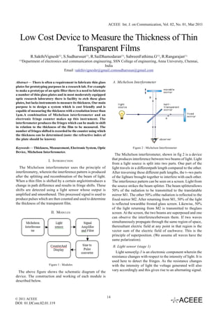
  • 1. ACEEE Int. J. on Communication, Vol. 02, No. 01, Mar 2011 Low Cost Device to Measure the Thickness of Thin Transparent Films R.SakthiVignesh(1), S.Sudharssun(1), R.SaiDhamodaran(1), SabreenFathima.G(1), R.Rangarajan(1) (1) Department of electronics and communication engineering, SSN College of engineering, Anna University, Chennai, India Email :sakthivigneshr@gmail.comsudharssun@gmail.com Abstract— There is often a requirement to fabricate thin glass A. Michelson Interferometer plates for prototyping purposes in a research lab. For example to make a prototype of an optic filter there is a need to fabricate a number of thin glass plates and in most moderately equipped optic research laboratory there is facility to etch these glass plates, but lacks instruments to measure its thickness. Our main purpose is to design a system which is cost friendly and is capable of measuring the thickness with a resolution lesser than 1μm.A combination of Michelson interferometer and an electronic fringe counter makes up this instrument. The interferometer produces the fringes which can be made to shift in relation to the thickness of the film to be measured. The number of fringes shifted is recorded be the counter using which the thickness can be determined (note: the refractive index of the plate should be known) Keywords— Thickness, Measurement, Electronic System, Optic Figure 2 : Michelson Interferometer Device, Michelson Interferometer. The Michelson interferometer, shown in fig 2 is a device I. INTRODUCTION that produces interference between two beams of light. Light from a light source is split into two parts. One part of the The Michelson interferometer uses the principle of light travels in a differentpath length compared to the other. interferometry, wherein the interference pattern is produced After traversing these different path lengths, the t--wo parts after the splitting and recombination of the beam of light. of the lightare brought together to interfere with each other. When a thin film is shifted by a certain angleitintroduces a The interference pattern can be seen on a screen. Light from change in path difference and results in fringe shifts. These the source strikes the beam splitter. The beam splitterallows shifts are detected using a light sensor whose output is 50% of the radiation to be transmitted to the translatable amplified and smoothened. This processed signal is used to mirror M1. The other 50% ofthe radiation is reflected to the produce pulses which are then counted and used to determine fixed mirror M2. After returning from M1, 50% of the light the thickness of the transparent film. is reflected towardthe frosted glass screen. Likewise, 50% of the light returning from M2 is transmitted to theglass II. MODULES screen. At the screen, the two beams are superposed and one can observe the interferencebetween them. If two waves simultaneously propagate through the same region of space, theresultant electric field at any point in that region is the vector sum of the electric field of eachwave. This is the principle of superposition. (We assume all waves have the same polarization). B. Light sensor (stage 1) Light sensorfig-3 is an electronic component wherein the resistance changes with respect to the intensity of light. It is used here to detect the fringes. As the resistance changes Figure 1 : Modules with the intensity of light the voltage generated will also The above figure shows the schematic diagram of the vary accordingly and this gives rise to an alternating signal. device. The construction and working of each module is described below. © 2011 ACEEE 14 DOI: 01.IJCom.02.01.119
  • 2. ACEEE Int. J. on Communication, Vol. 02, No. 01, Mar 2011 D. Sine to Pulse converter (stage 4) We use the comparator ICLM324, which consists of four op-amps. By comparing the output of signal from sensor with a reference voltage, a square wave results. Figure 3: Light Sensor C. Signal Amplifier and Filter (stage 2 & 3) The obtained signal is amplified using an instrumentation amplifier, adifferential amplifier which provides good impedance matching and filtered using a second order active low pass filter. Important characteristics include very low DC offset, low drift, low noise, very high open loop gain, very high common mode rejection ratio, and very high input Figure 6 : Sine to Pulse Converter impedances. E. Counter and Display (stage 5) We use IC 7490 which is a decade counter. It counts the number of pulses arriving at its input.The number of pulses counted (up to 9 in a single counter) appears in binary form. Figure 4 . Signal Amplifier Figure 7 : Counter IC We usethefilterto remove the high frequency noise present A seven-segment displayis a form of in the signal. By using optical equations and geometry the electronicdisplay device for displaying decimal frequency of the sinuous signal from the sensor can be numerals.IC7447 which is a BCD to &7-segment driver is derived mathematically represented as, usedfor interfacing the counter to the 7 segment display unit. F. Circuit diagram The complete circuit diagram is presented at the end of the paper (Fig 10). G. Working Stage 1: The fringes produced by the Michelson Interferometer are made to fall on the light sensor. The light sensor comprises of a light dependent resistor (LDR) connected with a 940Kohm in series and it is powered by a 9V supply. When there is a transition from light fringe to Figure 5 : Filter dark fringe the resistance value of LDR changes from low to high and the output voltage goes from high to low. Stage 2: This output from the sensor is amplified using an instrumentation amplifier. The approximate sine t- width of thin film wave like signal is given to one of the inputs of the k- constant in degrees/sec instrumentation amplifier and a suitable reference voltage is ì - refractive index thin film given to the other input. The reference is chosen such that ö- angle through which the glass plate is rotated the output does not saturate for any possible input value. We ë- wavelength of light use 1k ohm and 10 k ohm resistors to provide a gain of 10. © 2011 ACEEE 15 DOI: 01.IJCom.02.01.119
  • 3. ACEEE Int. J. on Communication, Vol. 02, No. 01, Mar 2011 Stage 3: The output of the instrumentation amplifier Where, is then given to a second order active low pass filter. It helps t- thickness of the plate. to eliminate the undesirable noise components present in the w- change in width from è = 0o to è =ö oscillating signal. The cutoff frequency is set to 1Khz so k- constant in degrees/sec that noise is eliminated. ì - refractive index thin film Stage 4: The low pass filter output is an amplified ö- angle through which the glass plate is rotated sine wave signal, which is given to the comparator IC, ë- wavelength of light n - fringe count LM324. This compares the incoming signal with given reference voltages to produce a ‘High’ or a ‘Low’.This J. Results obtained converts the approximate sine waves into pulses. Two A thin transparent film of thickness 1mm and refractive comparators are cascaded in series to produce sharp pulses. index 1.5 was taken as a test sample.When the film was Stage 5: We use a decade counter (IC7490) to count rotated through 20 degrees the counter showed a count of 99. the incoming pulses which gives a binary output (BCD). This is given to a BCD to 7-Segement decoder (IC7447) which Substituting this in the formula produces the required 8 digit digital output. This is given to the 7-segment display to show the count in numeric characters. In effect we are counting the number of light fringes that has completely crossed the light sensor when the thin film is rotated. This is then used to determine the unknown thickness of the thin film, using the previously stated formulae. Note: The refractive index of the thin film should be known. Though the comparator gives a ‘High’ for the light fringe and a ‘Low’ for the dark fringe, only the ‘High’ to ‘Low’ transitions are counted by the decade counter hence counting the number of light fringes which completely cross the sensor. H. Procedure NOTE: As the angle through which the glass plate is rotated Set up the Michelson interferometer unit. Use some is increased the fringe count increases. This reduces the standard laser for the light source. weight associated to each fringe count and thus the results Place the thin film on a rotating table and place it get closer to the actual value there by making the instrument in the lights path. more accurate. Make sure that the film is perpendicular to the light rays. III.CONCLUSIONS Rotate the thin film through some angle. This results in fringe shifts which are counted by the circuit. Thus a device for determining the thickness of a We now have the refractive index of the film, the thin transparent film was designed and constructed and its wavelength of light source, the angle through which working was tested using a sample glass plate. The challenges the film was rotated and the fringe count. we faced were the disturbance induced by the ambient light Substitute these values in the formula to get the and fluctuations due to vibrations. More over due to lack of thickness of the thin film. buffer space at the line of reference counter errors are induced due to multiple reference crossing. Nevertheless the device I. Formulae Used was able to provide good results when certain precautions were under taken. There are some improvements which can be made to overcome these problems. These are stated below. A. Enclosing the LDR in a black box with a pin hole to prevent hindrance from ambient lights. B. Using Schmitt Triggers to convert the sine waves into pulses. This will bring in a buffer space near the reference and will reduce the counting errors induced by multiple reference crossing. C. Increasing the counting range of the circuit. Presently it can count from 0 to 99. Increasing it by © 2011 ACEEE 16 DOI: 01.IJCom.02.01.119
  • 4. ACEEE Int. J. on Communication, Vol. 02, No. 01, Mar 2011 one or more digit will help in acquiringmore V. REFERENCES accurate reading. [1] Avadhanulu M.N. andKshirsagar P.G., “A Text Book of D. The rotation of the film can be motorised. The speed Engineering Physics”, S.Chand& Company Ltd., 7th Enlarged of which can be controlled using a microcontroller Revised Ed., 2005 programmed for pulse width modulation (in case [2] D.RoyChoudhry, Shail Jain, “Linear Integrated Circuits”, New of DC motors which are cheaper and smoother than the stepper motors. Age International Pvt. Ltd., 2000. [3] Gray and Meyer, ‘Analysis and Design of Analog Integrated IV.ACKNOWLEDGMENT Circuits’, Wiley International, 1995 [4] Palanisamy P. K., “Physics for Engineers”, Scitech Publications We would like to thank Mrs. Edna Elizabeth, associate (India) Pvt. Ltd., Chennai, Second Edition(2007). professor of SSN College of Engineering (Anna University) [5] Sergio Franco, ‘Design with operational amplifiers and analog andDr.S.Prita Nair,associate professor,Department of integrated circuits’, McGraw-Hill, 1997. Science & Humanitiesfor their invaluable support and suggestions throughout the development of this project. Figure 8 : The complete Circuit Diagram © 2011 ACEEE 17 DOI: 01.IJCom.02.01.119