Bd4101318323
•
0 recomendaciones•369 vistas

This document discusses a numerical study on the effect of jet shape on the flow and torque characteristics of a Pelton turbine runner. Four different jet shapes - circular, triangular, square and elliptical - were simulated using computational fluid dynamics (CFD) software, keeping the cross-sectional area of the jets constant. The results showed that the circular jet produced the highest hydraulic efficiency of 88.03%, distributing water most uniformly across the buckets. The triangular and square jets did not allow complete emptying of buckets before the next jet arrived, reducing efficiency. The elliptical jet had the lowest efficiency of 77.80%. In conclusion, circular jets were found to be most efficient for Pelton turbines.

Recomendados
Recomendados
Más contenido relacionado
La actualidad más candente
La actualidad más candente (20)
Similar a Bd4101318323
Similar a Bd4101318323 (20)
Último
Último (20)
Bd4101318323
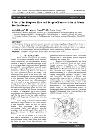
- 1. Vishal Gupta et al Int. Journal of Engineering Research and Applications ISSN : 2248-9622, Vol. 4, Issue 1( Version 1), January 2014, pp. 318-323 RESEARCH ARTICLE www.ijera.com OPEN ACCESS Effect of Jet Shape on Flow and Torque Characteristics of Pelton Turbine Runner Vishal Gupta*, Dr. Vishnu Prasad**, Dr. Ruchi Khare*** *(PhD Research Scholar, Department of Energy M.A. National Institute of Technology, Bhopal, MP, India) ** (Professor, Department of Civil Engineering M.A. National Institute of Technology, Bhopal, MP, India) *** (Assistant Professor, Department of Civil Engineering M.A. National Institute of Technology, Bhopal, MP, India) ABSTRACT In Pelton turbine, the energy carried by water is converted into kinetic energy by providing nozzle at the end of penstock. The shape of jet affects the force and torque on the bucket and runner of turbine. The nozzle of circular cross section is commonly used. In this paper attempt has been made to study the effect of four different jet shapes on the flow and torque characteristics of Pelton turbine runner through numerical simulation. Keywords - Multiphase flow, jet shape, Pelton turbine, free surface flow, nozzle I. INTRODUCTION Pelton turbines are tangential flow impulse turbines which operates under high head of water and require comparatively less quantity of water. Water is conveyed in penstocks from head race to the turbine in power house. Pelton turbine consists of a circular disc on which a number of buckets are evenly spaced around its periphery. Each bucket consists of two symmetrical halves having shape of semi-ellipsoidal cup. These symmetrical parts are divided by a sharp edged ridge called splitter. Water, at high head, flows through the penstock and at the end of penstock, one or more nozzles are fitted to convert all the available energy of water into kinetic energy. The water comes out of the nozzle as jet and impinges on the buckets, causing it to revolve. The impact of water jet produces force on bucket causing wheel to rotate. The jet of water splits equally by splitter and flows round the inner bucket surface and leaves at the outer edge of buckets. The buckets have special shape of double hemispherical cups. The rear of the bucket is designed such that the water leaving the bucket should not interfere with the passage of water to the preceding bucket. Model testing is the most common method for assessing the performance of any turbine. But this is time consuming, costly and does not provide detailed flow information. The improved computational facility and advanced numerical techniques made possible detailed flow analysis in given flow domain for design optimization of machines. In the last few decades, a lot of work has been done for optimisation of jet quality and bucket shape of impulse turbine. Many authors have worked for finding out most efficient shape of nozzle. Still www.ijera.com performance prediction of Pelton turbine for different shapes of jets is a thrust area for research because of multiphase and transient flow. Kotousov (2005) experimentally and Gupta et al. (2009) numerically found out that circular conical nozzles are most efficient ones. Perrig at al. (2006), Zoppe et al. (2006), Jost et al. (2010), Dynampally and Rao (2012) and Desai et al. (2012) have performed flow analysis of rotating Pelton turbine considering jet of circular cross section using various commercially available CFD codes. Zhang and Casey (2007) and Patel et al. (2010) have experimentally found out that for circular jet, jet core shifts from the axis of nozzle due to secondary flows generated by the bends or bifurcations present in the distributor of Pelton turbine system. With the help of CFD Peron et al (2008) improved the performance of Pelton turbine for two rehabilitation projects in Bordogna and Switzerland for circular jets. Gupta and Prasad (2012) analysed force experienced by the jet of different shapes on static bucket. Fig 1:Parts of Pelton Turbine 318 | P a g e
- 2. Vishal Gupta et al Int. Journal of Engineering Research and Applications ISSN : 2248-9622, Vol. 4, Issue 1( Version 1), January 2014, pp. 318-323 www.ijera.com In the present paper, numerical flow simulation of a six jet Pelton turbine shown in fig.1 for different shapes of jets with same cross sectional area has been carried out to access its performance at best efficiency point (BEP) by using commercial CFD code. II. GEOMETRIC MODELING In the present work, for the study of jet shape, the domain from exit of nozzle to runner was created. Due to limitation of computational power, only three symmetrical half jets with 10 symmetrical half buckets were created. The geometry of runner and stator is done separately. The stator is modeled for circular, triangular, square, ellipse jet inlet shown in fig 2 to fig 5. The symmetrical half of rotor is having 10 buckets as shown in fig 6. The modeling has been done in ICEM CFD. Fig. 4: Stator with square inlet Fig. 2: Stator with circular inlet Fig. 5: Stator with elliptical inlet Fig. 6: Rotor domain Fig. 3: Stator with triangular inlet III. MESH GENERATION The complete flow regime is discretised into grid having tetrahedral elements for flow space and www.ijera.com 319 | P a g e
- 3. Vishal Gupta et al Int. Journal of Engineering Research and Applications ISSN : 2248-9622, Vol. 4, Issue 1( Version 1), January 2014, pp. 318-323 triangular elements for surfaces. The mesh of stator domain with square inlet has been shown in fig.7. Prismatic elements have been applied near jet wall and bucket surface for better resolution of boundary layer. V. www.ijera.com FORMULAE USED The jet after striking the buckets with force, gets deflected towards the outlet of the buckets. The jet exerts torque on the buckets and thus the runner rotates. The following formulae are used for computation of parameters of turbine: Theoretical power input: PI g Q H (1) Power output: PO 2 N T 60 (2) Hydraulic efficiency: Fig. 7: Meshing of stator domain with square inlet IV. INPUT DATA AND BOUNDARY CONDITIONS Stator domain is kept stationary while the rotor domain is specified rotational speed of 820 rpm. The SST turbulent model given by Menter with automatic wall function was used as SST model is able to capture the flow in the region of higher shear stresses by solving a turbulence based model (k–ω) at the wall and k-ε in the region of bulk flow. In transient analysis, the time step plays a vital role. For larger time steps, the efficiency decreases and for smaller time steps, efficiency can be predicted well but the computational time increases drastically. So due to the limitation of computational power, time step corresponding to 1° (2.032×10 -4sec) runner rotation was considered. For numerically obtaining solution of a problem, boundary conditions at inlet and outlet are required to be defined and the solution of the problem depends on values given at boundary conditions. In present case, air and water with reference pressure of 1 atmospheric pressure are taken. Transient flow simulation with time step corresponding to l° runner rotation has been taken. Jet inlet is defined as inlet with water velocity of 30.7 m/s normal to surface. Jet symmetry, stator symmetry, rotor symmetry have been defined as symmetric type boundary conditions. Periodicity has been applied at both symmetric ends of stator and rotor. As the flow around impulse turbine is at atmospheric pressure, opening type boundary conditions are applied at stator side opening, stator top opening, rotor side opening and rotor mid opening with relative pressure of 0 atmospheric. Transient rotor-stator interface is set between both the domains. www.ijera.com h Po PI (3) Time step corresponding to 1° runner rotation: t 60 360 N VI. (4) MESH INDEPENDENCY TEST In numerical simulation, size of mesh and its quality affects the accuracy of results. The mesh independency test was carried out only for circular shape of jet. Same mesh size was given for other stators. The quality of the mesh was checked to be within the recommended values of ANSYS CFX. It was found that result becomes independent of stator mesh at 456213 nodes and for rotor, the torque becomes independent of mesh size after 1537618 nodes. VII. RESULTS AND DISCUSSIONS The flow simulation has been carried out at best efficiency point keeping cross sectional area of jets constant for each case. The numerical results for efficiency are validated with experimental results for circular jet at best efficiency point. The efficiency obtained from numerical simulation for circular jet is 88.03% which is close to experimental value of 91.5%. The results are analysed for water volume fraction iso-surfaces, pressure distribution within the flow domains. 320 | P a g e
- 4. Vishal Gupta et al Int. Journal of Engineering Research and Applications ISSN : 2248-9622, Vol. 4, Issue 1( Version 1), January 2014, pp. 318-323 www.ijera.com Fig 11: Water sheet for elliptical jet Fig 8: Water sheet for circular jet Spreading of water is more uniform for circular jet as seen in fig 8 and for triangular and square shaped jets in fig 9 and fig 10, water jet is unable to pass through the cut out which causes early interaction of water with bucket. In case of elliptical jet also, water spreads large over full surface of bucket as shown in fig 11. Fig 9: Water sheet for triangular jet Fig.12: Water volume fraction contour at mid span of bucket for various jet shapes at BEP Fig 10: Water sheet for square jet www.ijera.com It is observed from fig 12 that for circular and elliptical jets, buckets get fully emptied before reaching in front of next jet. But in case of triangular and square jets, the buckets are not completely emptied before reaching the next jet and this may create hindrance in the path of coming jet of water. This will lead in poor performance of turbine runner. 321 | P a g e
- 5. Vishal Gupta et al Int. Journal of Engineering Research and Applications ISSN : 2248-9622, Vol. 4, Issue 1( Version 1), January 2014, pp. 318-323 www.ijera.com Fig 16: Pressure contour on buckets for elliptical jet Fig 13: Pressure contour on buckets for circular jet From fig 13 to fig 16 it is observed that the highest pressure is observed at the deepest zone of the buckets. Splitter and cut out also experience higher pressure as compared to other parts of buckets in all cases. Fig 14: Pressure contour on buckets for triangular jet Fig 17: Variation of torque on buckets with angle of rotation Fig 15: Pressure contour on buckets for square jet www.ijera.com It is seen from fig 17 that torque increase is gradual and rate of increase is same for all jet shapes up to 40°. And again after 80° rotation, the value of torque becomes nearly constant for all jet shapes. Torque value increases when the buckets are in front of the jets and decreases as the distance between jets and buckets increases. Average value of torque is observed to be maximum for circular jet and minimum for elliptical jet. This is due to the less surface area of circular jet in contact with air. The values of hydraulic efficiency from numerical simulation for different jet shapes are given in table 1. It is seen that highest efficiency is achieved for circular jet and minimum for elliptical jet shape. 322 | P a g e
- 6. Vishal Gupta et al Int. Journal of Engineering Research and Applications ISSN : 2248-9622, Vol. 4, Issue 1( Version 1), January 2014, pp. 318-323 Table 1: Variation in hydraulic efficiency for different jet shapes Jet Circula Triangul Squar Elliptic Shape r ar e al 77.80 84.72 76.56 Numeric 88.03 al Efficienc y [6] [7] VIII. CONCLUSION It is found from numerical simulation of Pelton turbine at best efficiency point for different shapes that the circular jet are the most efficient giving highest efficiency. The spreading of water over the bucket is found to be more uniform for circular jet. The sharp edges of the jet other than circular shape give poor efficiency of the turbine because of uneven distribution of water on bucket surface. Very fine mesh is needed for performance prediction of Pelton turbines which requires very high computational power. NOMENCLATURE PI- power input (W) ρ- density of working fluid Q- discharge (m3/s) H- head (m) g- acceleration due to gravity (9.8 m/s2) ηh- hydraulic Efficiency (%) N- rotational speed of rotor (rpm) T- torque at rotor (N-m) PO- numerical Power Output (W) ηN - numerical Efficiency (%) [8] [9] [10] www.ijera.com Hydraulic Efficiency Measurements (IGHEM-2008), 3-6 September, 2008, Milano. K. Patel, B. Patel, M. Yadav and T. Foggia, Development of Pelton turbine using numerical simulation, transaction of IOP Science, 25th IAHR Symposium on Hydraulic Machinery and Systems, 2010 D. Jost, P. Meznar, A. Lipej, Numerical prediction of Pelton turbine efficiency, transaction of IOP Science, 25th IAHR Symposium on Hydraulic Machinery and Systems, 2010. V. Gupta and V. Prasad, Numerical Investigations for Jet Flow Characteristics on Pelton Turbine Bucket, International Journal of Emerging Technology and Advanced Engineering, Volume 2, Issue 7, July 2012, pp 364-370. P. Dynampally and V.S. Rao, CFD Analysis of Pelton Turbine, Proceedings of Thirty Ninth National Conference on Fluid Mechanics and Fluid Power, SVNIT, Surat, Gujarat, India, 2012, FMFP2012- 58. J.D. Desai,., V.A. Soni,., V.K. Chauhan,., S.S. Charania,. and K.C. Patel, Evaluation of Twin Jet Pelton Turbine Using CFD, Proceedings of Thirty Ninth National Conference on Fluid Mechanics and Fluid Power, SVNIT, Surat, Gujarat, India, 2012, FMFP2012- 194. REFERENCES [1] [2] [3] [4] [5] L.S. Kotousov, Measurement of the Water Jet Velocity at the Outlet of Nozzles with Different Profiles, Transaction of Technical Physics, Gases and Liquids, Vol. 50, No. 9, 2005, pp 1112-1118. Perrig, F. Avellan, J.L. Kueny and M. Farhat, Flow in a Pelton Turbine Bucket: Numerical and Experimental Investigations, Transaction of ASME, Vol.128, 2006,pp.350358. Zoppe, C. Pellone, T. Maitre and P. Leroy, Flow Analysis Inside a Pelton Turbine Bucket, Transaction of ASME, Vol. 128, 2006, pp.500-511. Zh. Zhang and M. Casey, Experimental Studies of the Jet of a Pelton Turbine, Proceeding of Institute of Mechanical Engineering, Part A: Journal of Power and Energy, Vol. 221, 2007, pp.1181-1192. M. Peron, E. Parkinson, Importance of Jet Quality on Pelton Efficiency and Cavitation, Proceeding of International Conference on www.ijera.com 323 | P a g e