Design and analysis of worm pair used in self locking system with development of manual clutch
•
1 recomendación•511 vistas

IJRET

Recomendados
Recomendados
Más contenido relacionado
La actualidad más candente
La actualidad más candente (20)
Destacado
Destacado (20)
Similar a Design and analysis of worm pair used in self locking system with development of manual clutch
Similar a Design and analysis of worm pair used in self locking system with development of manual clutch (20)
Más de eSAT Publishing House
Más de eSAT Publishing House (20)
Último
Último (20)
Design and analysis of worm pair used in self locking system with development of manual clutch
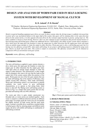
- 1. IJRET: International Journal of Research in Engineering and Technology eISSN: 2319-1163 | pISSN: 2321-7308 _______________________________________________________________________________________ Volume: 03 Issue: 08 | Aug-2014, Available @ http://www.ijret.org 427 DESIGN AND ANALYSIS OF WORM PAIR USED IN SELF-LOCKING SYSTEM WITH DEVELOPMENT OF MANUAL CLUTCH R. D. Ankush1 , P. D. Darade2 1 PG Student, Mechanical Engineering Department, P.G.M.C.O.E.., Wagholi, Pune, Maharashtra, India 2 Professor, Mechanical Engineering Department, S.I.T.S., Narhe, Pune, University of Pune, India Abstract Mostly in material handling equipment gear drives are used. In these systems when the driving torque is suddenly decreased due to power off or any mechanical failure at the input shaft of the system, then gears will be rotating either in the same direction driven by the system inertia, or in the opposite direction driven by the resistant output load due to gravity, spring load, etc. The latter condition is known as back driving. However, there are also solutions in gear transmission that prevent inertial motion or back driving using self-locking gears without any additional devices. Self-locking is the ability of gear system which constitute a drive which gives the input gear the freedom to rotate the output gear in either directions but the output gear locks with input when an outside torque attempts to rotate the output in either direction. Worm gear pair is also a self-locking gear pair but it is having very low efficiency around 40%, when made self-locking. In our project, self-locking property is obtained by using worm pair which is in mesh with each other. This system is simple in construction. The efficiency around 90% can be obtained as compared to 40% of conventional worm gear system. Keywords: worm, efficiency, self-locking --------------------------------------------------------------------***---------------------------------------------------------------------- 1. INTRODUCTION The term self-locking as applied to gear systems denotes a drive which gives the input gear the freedom to rotate the output gear in either directions but the output gear locks with input when an outside torque attempts to rotate the output in either direction. This characteristic is often sought after by designers who want to be sure that the loads on the output side of the system cannot affect the position of the gears. Worm gears are one of the few gear systems that can be made self-locking, but at the expense of efficiency, they seldom exceed 40% efficiency, when made self-locking. Worm pair self-locking system is an innovation in gearing combines two worm screws to give self-locking characteristics, or to operate as fast acting brake when power is shut off. The Mating worm self-locking system as shown in Fig.1 is a simple dual worm system that not only provided self-locking with over 90% efficiency. The worm pair drive is quite simply constructed, two threaded rods, or worm screws are meshed together. Each worm is wound in a different direction and has an different pitch angle. For proper mesh the worm axes are not parallel but slightly skewed. (If both worms had the same pitch angle, a normal, reversible drive would have resulted similar to helical gears.) But by selecting proper and different pitch angles, the drive will exhibit self-locking or combination of self-locking as desired. Fig -1: Worm pair system used in load lifting device 2. DESIGN PROCEDURE 2.1 Selection of Drive Motor Electric motor of following specification is used as the source of power in drive; 230 volt, 50Hz, 0.5 Amp Power =50 watt (1/15HP) Speed= 0 to 9000rpm TEFC construction Commutator Motor Input Torque at motor = 60x50 / (2 x Π x 400) = 1.19 N-m Reduction ratio of gear drive = 32.57 Tdesign = 38.74 N-m
- 2. IJRET: International Journal of Research in Engineering and Technology eISSN: 2319-1163 | pISSN: 2321-7308 _______________________________________________________________________________________ Volume: 03 Issue: 08 | Aug-2014, Available @ http://www.ijret.org 428 2.2 Design of Input Shaft 2.2.1 Material Selection Table -1: Material for Input shaft Designation Ultimate Tensile Strength N/mm2 Yield Strength N/mm2 40Cr1 1100 900 2.2.2 ASME Code for Design of Shaft Since the loads on most shafts in connected machinery are not constant, it is necessary to make proper allowance for the harmful effects of load fluctuations. According to ASME code permissible values of shear stress may be calculated from various relations. fsmax = 0.18 fult = 198 N/mm2 fsmax =0.3 fyt = 270 N/mm2 Considering minimum of the above values; fsmax = 198 N/mm2 This is the allowable value of shear stress that can be induced in the shaft material for safe operation. Shaft is provided with notch for locking; this will reduce its strength. Hence reducing above value of allowable stress by 25% fsmax = 148.5 N/mm2 This is the allowable value of shear stress that can be induced in the shaft material for safe operation. T= 38.74 x10³ N-mm Assuming 25% overload. T design = 1.25 x T = 48.47 x 10³ N-mm Check For Torsional Shear Failure of Shaft Assuming minimum section diameter on input shaft = 16 mm fsact = 16 ×Td 𝜋×d3 = 60.22 N/mm2 As fs act <fs all Input shaft is safe under torsional load 2.3 Design of Output Shaft 2.3.1 Material Selection Table -2: Material for Output shaft Designation Ultimate Tensile Strength N/mm2 Yield Strength N/mm2 40Cr1 1100 900 2.4 Design of Load Drum Hub Load drum hub can be considered to be a hollow shaft subjected to torsional load. 2.4.1 Material Selection. Table -3: Material selection for Load Drum Designation Ultimate Tensile strength N/mm2 Yield strength N/mm2 30C8 500 400 2.4.2 As Per ASME Code; fsmax = 81 N/mm2 Check for torsional shear failure:- T = π × fsact 16 × Do4 − Di^4 Do fsact =8.03 N/mm2 As; fsact<fsmax Hub is safe under torsional load 2.5 Design of Spur Gear Pairs for First Stage & Second Stage Reduction Power = 01/15 HP = 50 watt Speed = 1000 rpm b = 10 m Tdesign = 0.48N.m Sultpinion =Sult gear = 400 N/mm2 Service factor (Cs) = 1.5 dp = 16.5 T =T design = 0.48N-m T = Pt × dp 2 Pt =58.18 N. Peff = Pt × Cs Cv Neglecting effect of Cv as speed is very low Peff = 87.27 N--------(A) Lewis Strength equation Sb = m x b x fs xY Where; Y = 0.484 − 2.86 Z
- 3. IJRET: International Journal of Research in Engineering and Technology eISSN: 2319-1163 | pISSN: 2321-7308 _______________________________________________________________________________________ Volume: 03 Issue: 08 | Aug-2014, Available @ http://www.ijret.org 429 Pinion and gear both are of same material and with same number of teeth hence Sb = m x b x fs xYp = m x 10m x Sult/3 x 0.198 = 263.99 m2----------(B) Equation (A) & (B) 263.99 m2 = 87.2 m= 0.57 Selecting standard module =1.5 mm This is done according to the geometry of the flywheel drum standard gears and pinions of following details are selected. Hence a larger module is selected which gives maximum tooth depth. Hence the gear selected as below 2.5.1 Gear Data 2.5.1.1 First Pair No. of teeth on Flywheel gear = 74 No. of teeth on pinion = 10 Module = 1.5mm 2.5.1.2 Second Pair No. of teeth on Flywheel gear = 44 No. of teeth on pinion = 10 Module = 1.5mm 2.5.2 Design Check for First Stage Reduction Check for beam strength Fs = Sb Peff = 1.5x1.5x263.99 87.27 = 6.8 Since Factor of safety Fs = 6.8 design is safe Check for wear strength Sw = b x Q x d`p x K Q = 2xZp/(Zg-Zp) = 0.3125 d`p = mxZp = 15 K = 0.16 x (BHN/100)^2 = 1.96 (BHN = 350) Sw = 137.81 N Fs = Sw/Peff = 1.57 Design is safe 2.5.3 Design Check for Second stage reduction Check for beam strength Fs = Sb Peff = 1.5x1.5x263.99 87.27 = 6.8 Since Fcator of safety Fs = 6.8 design is safe Check for wear strength Sw = bxQxd`pxK Q = 2xZp/(Zg-Zp) = 0.5882 d`p = mxZp = 15 K = 0.16x(BHN/100)^2 = 1.96 (BHN = 350) Sw = 258.07 N Fs = Sw/Peff = 2.95 Design is safe 2.6 Design of Screw Assume Pitch – L = 10 mm C – Centre to center distance = 50 mm For input worm – Lead angle γ1 = 30 For Output worm – Lead angle γ2 = 50 From geometry we have 2.6.1 For Input Worm tan1 = L / d1 d = Nominal /outer diameter (mm) = 60.73 mm dc = core / inner diameter (mm) = 48.00 mm dm = mean diameter (mm) = 54.36 mm 2.6.2 For Output Worm tan2 = L / d2 d = Nominal /outer diameter (mm) = 36.38 mm dc = core / inner diameter (mm) = 27.00 mm dm = mean diameter (mm) = 31.69 mm 2.6.3 Design Check for Input Worm Mt = W x (dm/2) tan (+γ) Where , W= Axial load Ø = friction angle = Heilx angle 2.6.4 Friction Angle Table -4: Coeff. of friction under different condition Condition Average coefficient of friction Starting Running Average quality of material & workmanship & average running conditions 0.18 0.13 = tan Ø 0.18 = tan Ø Ø = 10.2 Assuming that load of 500 kg is carried by the drum of 100 mm diameter, then the resultant torque T= 5000X 50 = 250000 N-mm Mt = WX 31.7/2 x tan (10.2 + 5 --------(A) Mt = 4.3 X W N-mm --------(B)
- 4. IJRET: International Journal of Research in Engineering and Technology eISSN: 2319-1163 | pISSN: 2321-7308 _______________________________________________________________________________________ Volume: 03 Issue: 08 | Aug-2014, Available @ http://www.ijret.org 430 Equating (A) & (B) W = 58.13 KN ------ Theoretical load carrying capacity 2.6.5 Material Selection Table -5: Material Selection for Screw Designation Ultimate Tensile Strength N/mm2 Yield Strength N/mm2 40Cr1 1100 900 Direct Tensile or Compressive stress due to an axial load: fcact = W / ((/4 ) x dc2 ) fcact = 58.13 x 10³ / ((/4 ) x 272 ) fcact = 101.52 N/mm2 As fcact< fc all ; Screw is safe in compression. Torsional shear stress: T = Mt =/16 x fsact x dc3 250 x 10 3 = / 16 fsact x(27)3 fsact = 64.68 N/mm2 As fsact<fsall ; the screw is safe in torsion. 2.7 Design and Development of Manual Clutch Fig -2: Manual clutch 2.7.1 Construction This system is as shown in figure. This consists of a bearing, a load drum, a hub and a metallic key which is welded to the hub with the help of a pivot as shown figure. 2.7.2 Working In case of self-locking systems the occasion can arise where it becomes desirable to quickly release the load. This could be accomplished by introducing a clutch between the pulley and worm but such clutches are generally expensive and space consuming. This invention comprises of a modification of a self-locking mating worm drive. In our system we have used a load drum which is connected to the output worm of the system. This load drum is connected to the output shaft through a hub. This load drum is fitted to the hub with the help of a bearing. Due to this bearing the load drum can rotate freely relative to the hub. This relative motion of drum can be interrupted with the help of a key or lever. The load drum is provided with a slot at its end towards hub. The key is welded to the hub and it is provided with a fulcrum. When this key is straight then it’s one end is engaged with the load drum due to this position the load drum gets fixed with the hub and relative motion between them is avoided. Now when there is a situation when it is required to release the lifted load we can release it by applying some axial force at the free end of the key towards left side as shown in figure. When we apply force at its free end then its another end gets disengaged from the slot provided in the load drum and it is now free to rotate relative to the hub. Thus the self-locking property can thus be removed at will. 3. EXPERIMENTAL RESULTS AND VALIDATION 3.1 Conventional Worm Gear System The tests are carried out on the conventional system i.e. Worm and Gear system. In these tests the values of efforts required to lift different amounts of loads. By tabulating these values and by referring various empirical relations for this system efficiency of this system can be determined. The experimental data, sample calculations along with their respective graphs are given below, 3.1.1 Observation Table Table -6: Observation Table for conventional system Sr. No. Load (gm) Effort (gm) Load (N) Effort (N) 1 1500 75 14.715 0.73575 2 2000 95 19.62 0.93195 3 2500 130 24.525 1.2753 4 3000 160 29.43 1.5696 5 4000 210 39.24 2.0601 6 4500 235 44.145 2.30535 7 5000 250 49.05 2.4525 Sample Calculation (For 4000 Gm Load) Let L = Radius of the wheel r = Radius of the load drum W = Load lifted P = Effort applied to lift the load T = Number of teeth on the worm wheel If the worm is single threaded (i.e., for one revolution of the wheel, the worm pushes the worm wheel through one tooth) then for one revolution of the wheel the distance moved by the effort = 2πL
- 5. IJRET: International Journal of Research in Engineering and Technology eISSN: 2319-1163 | pISSN: 2321-7308 _______________________________________________________________________________________ Volume: 03 Issue: 08 | Aug-2014, Available @ http://www.ijret.org 431 The load drum will move through = 1/ T revolution Distance, through which the load will move = 2πr / T V.R = (Distance moved by P) / (Distance moved by W) = (2πL / (2πr / T)) = LT / r In general, if the worm is n threaded then, V.R = LT / nr M.A = W / P η = M.A / V.R Load is taken in gm but for our calculations we have to convert it into N. Load W = 4000 gm = 4000/1000x9.81=39.24 N Similarly Effort P = 210 gm = 210/1000x9.81 = 2.0601 N Now for our system V.R. (Velocity Ratio) is 37.14 M.A. = W/P = 39.24/2.0601 = 19.04 Therefore Efficiency of the system η = M.A. / V.R. = 19.04/37.14 = 51.18 % 3.1.2 Result Table Results in terms of efficiency for different amount of loads and efforts are calculated according to the sample calculations provided above and are tabulated as given below, Table -7: Observation Table for conventional system Sr. No. Load (N) Effort (N) Efficiency Avg. Efficiency 1 14.71 0.735 53.850 52.78 % 2 19.62 0.931 56.684 3 24.52 1.275 51.779 4 29.43 1.569 50.484 5 39.24 2.060 51.286 6 44.14 2.305 51.558 7 49.05 2.452 53.850 From above result table we get the efficiency of the conventional worm gear system as 52.78%. 3.2 Mating Worm Pair System Test on Mating Worm Pair system are conducted in order to determine the efficiency of the system. For calculating efficiency of the system we need to determine the input and output power of the system. By making suitable arrangements as discussed above we have conducted test on this system for various loads and the experimental data and results are as follows, 3.2.1 Observation Table Input Shaft These readings are taken on the output shaft of the motor in order to calculate the input power to mating worm pair system. The arrangement for setup is as discussed above. And the readings observed are as follows, Table -8: Observation table for input shaft Sr. No. W in gm W in N RPM N 1 100.00 0.98 46.07 2 200.00 1.96 45.69 3 300.00 2.94 45.31 4 400.00 3.92 44.95 5 500.00 4.91 44.42 6 600.00 5.89 43.84 7 700.00 6.87 43.27 8 800.00 7.85 42.78 9 900.00 8.83 42.27 10 1000.00 9.81 41.55 Output Shaft These readings are taken on the output shaft of the mating worm pair system in order to calculate the output power of the system. The arrangement for setup is as discussed above. And the readings observed are as follows, Table -9: Observation table for Output shaft Sr. No. W in gm W in N RPM N 1 0.00 0.00 38.90 2 100.00 0.98 38.60 3 200.00 1.96 38.20 4 300.00 2.94 37.60 5 400.00 3.92 37.20 6 500.00 4.91 36.90 7 600.00 5.89 36.70 8 700.00 6.87 36.50 9 800.00 7.85 36.30 10 900.00 8.83 36.00 11 1000.00 9.81 35.80 Sample Calculations (For 500 Gm Load) For Input Power Input Torque:- Tip = Weight in pan x Radius of Dynamometer Pulley = (0.5 x 9.81) x 36 = 176.6 N.mm Tip= 0.1766 Nm Input Power:- (Pi/p) Pi/p = 2πNTip 60 = 2 × π × 44.42 × 0.1766 60 Pi/p =0.82 watt
- 6. IJRET: International Journal of Research in Engineering and Technology eISSN: 2319-1163 | pISSN: 2321-7308 _______________________________________________________________________________________ Volume: 03 Issue: 08 | Aug-2014, Available @ http://www.ijret.org 432 For Output Power Output Torque:- Top = Weight in pan x Radius of Dynamometer Pulley = (0.5 x 9.81) x 36 = 176.6 N.mm Top= 0.1766 Nm Output Power:- (Po/p) Po/p = 2πNTop 60 = 2 × π × 36.90 × 0.1766 60 Po/p =0.6882 watt Efficiency:- ( η ) η = Po/p / Pi/p = 83.07 % 3.2.2 Result Table Table -10: Result table for mating worm pair system Sr. No. W in gm Speed (No/p) Torque (To/p) Power (Po/p) Efficiency (η) Avg Efficiency (ηAvg) 1 100 38.60 0.035 0.143 83.79 84.046 2 200 38.20 0.071 0.283 83.61 3 300 37.60 0.106 0.417 82.98 4 400 37.20 0.141 0.551 82.77 5 500 36.90 0.177 0.683 83.07 6 600 36.70 0.212 0.815 83.72 7 700 36.50 0.247 0.945 84.35 8 800 36.30 0.283 1.074 84.85 9 900 36.00 0.318 1.199 85.17 10 1000 35.80 0.353 1.325 86.15 3.3. Comparison of Efficiencies Of Conventional Worm Gear And Mating Worm Pair System Chart -1: Graph of efficiency comparison of conventional & Worm pair system We have plotted the efficiencies of conventional worm gear system and worm pair system. We have plotted total seven readings for comparison of both the systems. From graph we can see that the efficiency of conventional worm gear system lies in between 50% to 60% with an average efficiency of 52.78% while the efficiency of mating worm pair system lies in between 80% to 90% with an average efficiency of 84.04%. 4. CONCLUSIONS From above results and observation we can conclude that the mating worm pair system also exhibits a self-locking ability as that of conventional worm gear system. Also the efficiency of the mating worm pair system is also greater than that of conventional worm gear system. So with having some further modifications related to dimensions of worms such as its helix angle, lead angle and other parameters we can replace this conventional worm gear system with new worm pair self-locking system. 5. FUTURE SCOPE The present set up is manually operated, hence this limits the load carrying ability of the system, withan appropriate gearing we can increase the mechanical advantage thereby improving the load carrying ability. The present system has an open casing thereby the need of external lubrication may arise, with appropriate modifications we can make cast iron casing to retain the lubricating oil. By employing some improved processes and fine workmanship in manufacturing we can further achieve improved quality of parts and which may affect the results in positive manner. ACKNOWLEDGMENTS We thank colleagues of P.G.M.C.O.E., Wagholi, Pune and S.I.T.S., Narhe, Pune for their constant feedback on the paper. We also thank the anonymous reviewers for their valuable comments. REFERENCES [1] Fenge Li Shenzhen & Jing Ning Ta of Hongkong “Worm Gear Drive.” United States Patent Office No.8, 051,737 B2 dated on 8 Nov 2011 [2] JakhinBoaspopper&KiryatMotzkin of Israel “Cooperating Wedges including Mating Worm.” United States Patent Office No.2, 973,660 dated on 07 Mar 1961 [3] Winker W. Panjuchin& Vladimir of Russia “Self- Locking Dual Worm Gear &The Tools Needed to Produce it.” United States Patent Office No.5, 522,278 A dated on [4] Alfonso Hilado, Paranaque, Rizal of Republic of the Philippines “Self-Locking Differential Mechanism.” UnitedStates Patent Office No.3,095,761 dated on 2 July 1963 0 10 20 30 40 50 60 70 80 90 100 1 2 3 4 5 6 7 Efficiency(η) Sr. No. Comparison of Efficiency Dual mating Worm system Conventi onal Worm Gear
- 7. IJRET: International Journal of Research in Engineering and Technology eISSN: 2319-1163 | pISSN: 2321-7308 _______________________________________________________________________________________ Volume: 03 Issue: 08 | Aug-2014, Available @ http://www.ijret.org 433 [5] David W. Pessen of Israel “Quick Release Mechanism for Self-Locking Mating Worms.” United States Patent Office No.3, 776,060 dated on 04 Dec 1973 [6] Robert W.Jenny&Believue Wash from the Boeing Company of Washington “Automatic Anti Friction Dual ratio Motion Convertor.” United States Patent Office No.3, 295,385 dated on 3 Jan 1967 [7] Adam Macheta and Sebastian Kania of (EC Engineering) “Literature Survey : Worm Gear Losses .” [8] Handbook of Gear Design (Second Edition) by Gitin M Maitra [9] PSG Design Data book compiled by PSG College of Technology, Coimbatore [10] Design of Machine Element by V. B. Bhandari [11] Introduction to Machine Design by V. B. Bhandari [12] http://en.wikipedia.org/wiki/Worm_drive