DESIGN OPTIMIZATION AND VALIDATION THROUGH FE ANALYSIS OF PARALLEL MOTION FENDER
•
2 recomendaciones•635 vistas

This document summarizes research on optimizing the design of parallel motion marine fenders. Parallel motion fenders consist of a fender panel supported by arms attached to a torsion tube. The current design fails due to stresses on the torque arm from ship impacts. The researchers modeled an existing parallel motion fender and analyzed stresses from ship impacts at different angles. They then modified the design by adding a gear mechanism to distribute loads and eliminate the torque arm. Analysis of the new design found stresses below allowable limits with a safety factor of 4.42, indicating the gear mechanism achieves the goal of optimizing the parallel motion fender design.

Recomendados
Más contenido relacionado
La actualidad más candente
La actualidad más candente (20)
Destacado
Destacado (8)
Similar a DESIGN OPTIMIZATION AND VALIDATION THROUGH FE ANALYSIS OF PARALLEL MOTION FENDER
Similar a DESIGN OPTIMIZATION AND VALIDATION THROUGH FE ANALYSIS OF PARALLEL MOTION FENDER (20)
Más de ijsrd.com
Más de ijsrd.com (20)
Último
Último (20)
DESIGN OPTIMIZATION AND VALIDATION THROUGH FE ANALYSIS OF PARALLEL MOTION FENDER
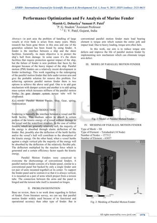
- 1. IJSRD - International Journal for Scientific Research & Development| Vol. 1, Issue 9, 2013 | ISSN (online): 2321-0613 All rights reserved by www.ijsrd.com 1978 Performance Optimization and Fe Analysis of Marine Fender Manish G. Dobariya1 Sumant P. Patel2 1 P. G. Student 2 Assistant Professor 1, 2 U. V. Patel, Gujarat, India Abstract—in port area the problem of handling of large vessels at river bank is arises from many years. Many research has been gone throw in this area and one of the generalize solution has been found by using fender. A fender is the interface between a ship and the shore facilities. Generally, its main objective is to protect the ship’s hull from damage. In some cases it’s the shore facilities that require protection against impact of the ship, but the failure of fender is new problem that faces by the designer because of the heavy impact of the ship. Parallel motion (PM) fenders are a relatively recent development in fender technology. This work regarding to the redesigning of the parallel motion fender that fails under torsion arm and give the probable solution for remove this problem. For achieving optimize parallel motion fender there is two options to achieve the above said goal. One is to add gear mechanism with damper system and another is to add spring mass system which increases stiffness of the parallel motion fender. In gear damper system torque tube will be eliminated. Key words: Parallel Motion Fender, Ship, Gear, spring, Optimization I. INTRODUCTION Fendering is basically the interface between a vessel and the berth facility. This medium serves to absorb a certain portion of the kinetic energy of a vessel without damage to the vessel and the waterfront structure. In the case of rubber fenders, which are generally relatively soft, the majority of the energy is absorbed through elastic deflection of the fender. But, possibly also the deflection of the berth facility and/or the vessel’s hull will contribute to the absorption of the kinetic energy. On the other hand, when a vessel berths against a single vertical pile the majority of the energy will be absorbed by the deflection of the relatively flexible pile. The deflection multiplied by the reaction force which is generated and a certain efficiency factor equals the kinetic energy. Parallel Motion Fenders were conceived to overcome the shortcomings of conventional fenders. A parallel motion fender consists of a fender panel, similar to a conventional panel but backed by only a single fender unit (or pair of units mounted together) at its center. To support the fender panel and to restrain it so that it is always vertical, it is mounted on a pair of arms which project from a torsion tube. The connection between the arms and the panel is hinged and the torsion tube itself is mounted on hinges. II. PROBLEM DEFINITION Base on review, there is no work done regarding to failure of fender. From literature survey, we can say that parallel motion fender widely used because of its functional and operational accuracy than other type of fender. But in conventional parallel motion fender main load bearing element is torque arm which sustain the entire jerk and impact load. Due to heavy loading, torque arm often fails. In this work, our aim is to reduce torque arm defects and improve the life of parallel motion fender by implementing new mechanism which can eliminate torque arm defect. III. MODEL OF PARALLEL MOTION FENDER Fig. 1: Model of Parallel Motion Fender IV. MESHING OF PARALLEL MOTION FENDER Type of Mesh: - 3D Type of Element: - Tetrahedral (10 Node) Number of Nodes: - 157312 Number of Element: - 63037 Fig. 2: Meshing of Parallel Motion Fender
- 2. Performance Optimization and Fe Analysis of Marine Fender (IJSRD/Vol. 1/Issue 9/2013/0070) All rights reserved by www.ijsrd.com 1979 V. APPLY SHIP FORCE Fig. 3: Apply Transient Force VI. RESULT OF PM FENDER (FOR 0 DEGREE ANGLE SHIP IMPACT) EQUIVALENT (VON- MISES) STRESS Fig. 4: Result of PM Fender (For 0 Degree Angle Ship Impact) VII. RESULT OF PM FENDER (FOR 20 DEGREE ANGLE SHIP IMPACT) Fig. 5: Result of PM Fender (For 0 Degree Angle Ship Impact) VIII. RESULT & DISCUSSION At Torque Arm Attachment Material ST 52 – 355 MPa 0 Degree 20 Degree Von Misses Stresses(MPa) 279.11 371.63 Maximum Shear Stresses(MPa) 149.85 199.81 Factor of Safety 1.27 0.95 Table. 1: Results From this result we can say that maximum stresses occur at the torque arm attachment and minimum life is also generated at the torque arm. For 0 degree ship impact, fender is capable for sustaining load. For 20 degree ship impact, fender is not capable to sustain load and minimum life is generated at the torque arm. So in next chapter we modify design and try to reduce stresses on torque arm attachment. IX. MODIFICATION Fig. 6: Modification Using Gear Mechanism In Parallel Motion Fender, when the ship strikes a Fender First Cone Fender absorb shock energy when the limit of cone fender is complete. It transmit it load to upper damper but in some cases when the ship strikes only upper surface of the Parallel Motion Fender Upper Damper absorb more energy and its compression movement is more than lower Damper which restrict the parallel movement so we put gear mechanism for uniformly guide. When the Upper Damper Compresses, the another side gear which attach to the Front Side of the Fender rotates which move tangentially on the shaft mounted gear. Shaft having two gear one upper and second lower side. When the Upper gear rotates at the same time lower gear is also rotate which results Parallel Operation of Fender. X. APPLY TRANSIENT FORCE Fig. 7: Apply Transient Force Using Gear Mechanism
- 3. Performance Optimization and Fe Analysis of Marine Fender (IJSRD/Vol. 1/Issue 9/2013/0070) All rights reserved by www.ijsrd.com 1980 XI. RESULTS OF PM FENDER USING GEAR MECHANISM (10 DEGREE STRIKE ANGLE) Fig. 8: Von-Mises Stress (0 Degree Strike Angle) XII. RESULTS OF PM FENDER USING GEAR MECHANISM (20 DEGREE STRIKE ANGLE) Fig. 9: Von-Mises Stress (20 Degree Strike Angle) XIII. RESULT OF PARALLEL MOTION FENDER USING GEAR MECHANISM At Gear Tooth (Material ST 52 = 355 MPa) 0 Degree 20 Degree Von Mises Stress (MPa) 51.967 80.299 Maximum Shear Stress 29.265 43.038 Factor of Safety 6.83 4.42 As shown above, the analysis has been performed for the force applied at normal direction to the frontal panel and 20 degree. Transient analysis has been performed for all 2 cases. The stress value is coming less than the allowable stress value (80.299 MPa – force applied on 20 degree, worst case). After modified design, the stress value is coming much less than the existing design. XIV. CONCLUSIONS From above thesis work we can conclude that parallel motion fender gives better results than any type of fender because in parallel motion fender side impact is taken care by torque arm so only parallel impact load is transferred to cone fender so the life of cone fender increases. Meanwhile the impact carrying element torque arm will fail often so in this thesis our aim is to modify parallel motion fender in such a way so we can eliminate torque arm. In gear damper system, when the ship strike the maximum generated stress in the system is 80.299 MPa which is less than allowable limit of material. In this design the factor of safety is 4.42. REFERENCES [1] Guidelines for the design of fender 2002- PINAC [2] Dr. MoujalliHourani, Mr, Reeves Whitney, Mr. Raymond Gizzi P.E “Fender system selection using Ansys.” [3] Zhiyu Jiang, MintongGu. “Optimization of a fender structure for the crashworthiness” design.” Elsevier- Materials and Design 31 (2010) [4] Shigeki Sakakibara, Masayoshi Kubo.” Ship berthing and morring monitoring system by pneumatic type fenders” - Ocean engineering 34 (2007) 1174-1181 [5] A.S. Bradshaw, C.D.P. Baxter “Simple dynamic model for fender pile analysis and design”- Ocean Engineering, (ASCE -2006) [6] Gokdeniz Neser, Deniz Unsalan “Dynamics of ships and fenders during berthing in a time domain”- Ocean Engineering 33 (2006) [7] Tim Beckett. “ Parallel Motion Fenders; Some design consideration including immersion of fender cone” [8] Wuttrich, Jerry Wekezer, Nur Yazdani “Performance evaluation of existing bridge fenders for ship impact” [9] T.T.Lee. “Design criteria recommended for marine fender systems”- coastal engineering 10) Shigeru Udea, Toshihiko Hirano, Seigi Yamase “Statistical design of fender for berthing ship“- International offshore and polar engineering conference [10] Book: Design of Machine Element – V B BHANDARI