Harmonic Mitigation Method for the DC-AC Converter in a Single Phase System
•
3 recomendaciones•379 vistas

This document summarizes a research paper that proposes a harmonic mitigation method for a DC-AC converter without using a low pass filter. Specifically, it suggests using sine wave modulation of the converter along with injection of specific harmonics calculated using Fourier analysis to cancel out existing harmonics. A proportional-resonant integral controller is also used to eliminate any DC offset. Simulation results show the total harmonic distortion is reduced to 11.15% using this approach, avoiding the need for an output filter. The proposed method continuously monitors and mitigates harmonics in the output to improve power quality.

Recomendados
Recomendados
Más contenido relacionado
La actualidad más candente
La actualidad más candente (20)
Destacado
Similar a Harmonic Mitigation Method for the DC-AC Converter in a Single Phase System
Similar a Harmonic Mitigation Method for the DC-AC Converter in a Single Phase System (20)
Más de IJTET Journal
Más de IJTET Journal (20)
Último
Último (20)
Harmonic Mitigation Method for the DC-AC Converter in a Single Phase System
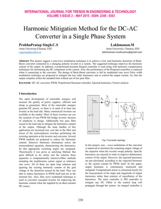
- 1. INTERNATIONAL JOURNAL FOR TRENDS IN ENGINEERING & TECHNOLOGY VOLUME 5 ISSUE 2 – MAY 2015 - ISSN: 2349 - 9303 230 Harmonic Mitigation Method for the DC-AC Converter in a Single Phase System PrabhuPratap Singh.C.S Lakhmanan.M Anna University,Chennai, EEE Anna University, Chennai, EEE csppsingh@yahoo.in lakshmanan.muthuramu@gmail.com Abstract-This project suggest a sine-wave modulation technique is to achieve a low total harmonic distortion of Buck- Boost converter connected to a changing polarity inverter in a system. The suggested technique improves the harmonic content of the output. In addition, a proportional-resonant Integral controller is used along with harmonic compensation techniques for eliminating the DC component in the system. Also, the performance of the Proposed controller is analyzed when it connecting to the converter. The design of Buck-Boost converter is fed by modulated sine wave Pulse width modulation technique are proposed to mitigate the low order harmonics and to control the output current. So, that the output complies within the standard limit without use of low pass filter. Keywords- DC-AC converter, PWM, Proportional Resonant controller, Injected harmonics, Fourier analysis I Introduction The rapid development of renewable energies will increase the quality of power supplies, efficient and cheap in generation. Most of the renewable energies generate DC power, so there is in need of at least one inverter at the load side. Many commercial inverters are available in the market. Most of those inverters are use the variation of sine PWM full bridge inverter, because of simplicity in design. Additionally low pass filter isused at the load side to mitigate the harmonics content of the output. Although the main hurdles of this application are increased size, cost due to the filter and losses of the semiconductor switches performing the inverting operation at the inverter and converter. Several PWM methods are proposed to reduce the Harmonic content. Selective Harmonic elimination solves the transcendental equations characterizing the harmonics, So that appropriate switching angles are computed. Theoretically it was prove as satisfying Method. But quite difficult to do online and the solution these equations is computationally intensive.Other methods including the modification carrier signal or reference sine wave. All of them are open loop schemes and ignoring the existing harmonic content of the grid voltage or the distortion caused by the load. They can able to reduce harmonics in PWM itself and not at the terminal bus. Also, Sine wave modulated technique is used in converter cascaded inverter for improving the harmonic content when the supplied by an ideal constant DC source. Fig.1 Converter topology In this project, sine – wave modulation of the converter is improved to minimize the remaining output voltage of the capacitor when the inverter swaps polarity. Specific harmonics are injected in order to improve theharmonic content of the output. However, the injected harmonics are pre-calculated, according to the expected harmonic in the system created by PWM itself. In this paper, output harmonic is continuously monitored and mitigated. Computational power is consumed mostly for the measurement of the angle and magnitude of output harmonics rather than creation of cancellation of the harmonics. The main controller is PRI controller to mitigate any DC Offset in the control loop will propagate through the system. An integral controller is
- 2. INTERNATIONAL JOURNAL FOR TRENDS IN ENGINEERING & TECHNOLOGY VOLUME 5 ISSUE 2 – MAY 2015 - ISSN: 2349 - 9303 231 used along with the PR controller to ensure that there is no DC in the output of the inverter side. 2 PWM Techniques and its modification 2.1 Previously proposed techniques: The duty cycle of the converter is continuously calculated under constant frequency, so the output DC voltage equals the rectifier voltage. D=VDC out/ (VDC out +VDC in)…. (1) The inverter output containing the higher order harmonics caused by switching operation of the switches. The method of modulation is to reduce the remaining DC voltage at the output of the DC converter is reduced. When the capacitor has low level of voltage, then the harmonic contents are improved. Fig.2. Block diagram of the DC elimination The idea of reduction of remaining voltage of the capacitor is accomplished from the block diagram of Fig. 2. First the ac voltage is sampled in the process. Then, the Vac, rms and Reference voltage is compared in the error compensation block .then the duty cycle of the sine wave of 50HZ is multiplied with error compensation. Finally the resultant output is compared with triangular carrier waveform. Initially, the ac voltage is rectification is proposed for VDC min error compensation and integrated with comparator for duty cycle generation. 2.2. Suggested modulation technique In order to tackle the low order harmonics, cancellation scheme was proposed with Adaptive harmonic compensation techniques based on the injection of mirror harmonics during the construction of the modulation signal of the DC converter. Harmonic content of the output is calculated with Fourier analysis. Then, add low order harmonics to modulation sine wave of the fundamental frequency, but phase difference of 180 degree to the output harmonics is to be eliminated. hA(t)=A sin (2*pi*f*t + a) hB(t)=B sin(2*pi*f*t + b) hC(t)=C sin(2*pi*f*t + c)……..(2) Where A,B, C and a, b, c are the phase and magnitudes and phase angles. All the three harmonics are at the same frequency, so convert the function (2) to phasors. hA(t) to AeJA hB(t) to Bejb hC(t) to Cejc ………(3) The resulting harmonics equals the summation of the injected and existing harmonics. Knowing the magnitude and phase of each harmonic in the output, without harmonic injection, allows us to set the magnitude of the mirror harmonic injected in this iteration. Then it will allow for Fourier analysis of the output to perform again. Fig.3. creation of pulses for converter
- 3. INTERNATIONAL JOURNAL FOR TRENDS IN ENGINEERING & TECHNOLOGY VOLUME 5 ISSUE 2 – MAY 2015 - ISSN: 2349 - 9303 232 Fig.4. VDC min elimination 3 Current control scheme with modulation technique: The PRI controller was introduced in the converter to ensure that there is no DC offset in the output side. Many current controlling scheme was implemented for current control in the inverter side .In this project, Current control scheme was implemented in the Converter side to enhance the modulation technique. Multi-resonant controller are used with selective harmonic elimination for improving the harmonic standards. The main advantage of this method was simplicity in implementation of the resonant blocks. But, major drawbacks of this method is affecting the performance of the controllers due to the variation in the grid frequency. This will increase the complexity to control the variation in the grid frequency. Also, the repetitive controller with harmonic cancellation methods are sensitive to the frequency variation. This will affect the stability of the system. The PR controller was used along with Integral block to overcome those difficulties. The integral blocks along with the PR to ensure that there is no DC offset in the output of the system.It was coupled with Sine wave modulation technique. Fig.5. block diagram of PRI controller The PRI controller was derived from the following equation, Gi = Ki/s………………(4) Gpr(s) = Kp + KrS/S2 +Wo2 ………………(5) The plant transfer function is modeled as Gplant (s)= VDC/Rs + SLs ……….(6) …………(7) The above equation shows the PI controller parameters are then plugged in for the PR controller parameters. For the PR controller,the expressions obtained are used for the proportional and resonant gain respectively from the equations (8) and (9), ……………(8) ………..(9)
- 4. INTERNATIONAL JOURNAL FOR TRENDS IN ENGINEERING & TECHNOLOGY VOLUME 5 ISSUE 2 – MAY 2015 - ISSN: 2349 - 9303 233 ………(10) Fig. 6. PR Controller transfer function block Table I Parameters and their value Parameter meaning values VDC DC voltage 65V Ls Source inductance 5mH L Inductance across converter 3mH C Capacitance 29Mf R Load resistance 54ohms Kp Proportional gain 3.2 Kr Resonant term 594 Ki Integral term 100 4 Simulation results A DC source of 65v is given to the supply. The buck- Boost converter operator at a switching frequency of 20 kHz and Inverter changes polarity at 50Hz. Fig.7. simulation of Buck-boost converter without using filter
- 5. INTERNATIONAL JOURNAL FOR TRENDS IN ENGINEERING & TECHNOLOGY VOLUME 5 ISSUE 2 – MAY 2015 - ISSN: 2349 - 9303 234 Fig.8. output voltage and current Fig.9. FFT analysis The total harmonic distortion of the overall system is about 11.15%. By further improving the performance of the PRI controller, the THD of the system will be reduced within the standard limit. The Fig.9. Shows the FFT analysis of the system. For the initial state, No harmonics are to be injected. Then, Fourier analysis of the output voltage was calculated. By knowing the harmonic of the output voltage and harmonics are already injected. Then alter harmonic injection in order to cancel harmonics at the output was again fed to the Fourier analysis. 5 Conclusion The converter is buck-Boost converter in series with polarity changing inverter. Specific harmonics are cancelled by using Fourier analysis of the injected harmonics. PRI controller with the VDC elimination method are used to improving the harmonic content. The method makes no distinction of harmonics creation within the converter or supplied from the sources. The complete current of PRI controller are also used in Solar PV application for cancellation of the DC offset to improving the harmonics standard. The transient response of the whole system was studied and increase the overall performance of the system. The PRI controller and Modulated sine wave method together improve the quality of the current injected into the load side. References [1] Konstantinos G. Georgakas, Panagis N. Vovos, Member, IEEE, and Nicholas A. Vovos, Senior Member, IEEE, “Harmonic Reduction Method for a Single-Phase DC–AC Converter Without an Output Filter” IEEE TRANSACTIONS ON POWER ELECTRONICS, VOL. 29, NO. 9, SEPTEMBER 2014 [2]J. Rodriguez, J. S. Lai, and F. Z. Peng, “Multilevel inverters: A survey of topologies, controls, and applications,” IEEE Trans. Ind. Electron., vol. 49, no. 4, pp. 724–738, Aug. 2002. [3] J. Kumar and B. Das, “Selective harmonic elimination technique for a multilevel inverter,” in Proc. 15th Nat. Power Syst. Conf., Dec. 2008,pp. 608–613. [4] J. N. Chiasson, L. M. Tolbert, K. J. McKenzie, and Z. Du, “Elimination of harmonics in a multilevel converter using the theory of symmetricpolynomials and resultants,” IEEE Trans. Control Syst. Technol., vol. 13, no. 2, pp. 216–223, Mar. 2005.
- 6. INTERNATIONAL JOURNAL FOR TRENDS IN ENGINEERING & TECHNOLOGY VOLUME 5 ISSUE 2 – MAY 2015 - ISSN: 2349 - 9303 235 [5] B. Ozpineci, L. M. Tolbert, and J. N. Chiasson, “Harmonic optimization of multilevel converters using genetic algorithms,” IEEE Power Electron.Lett., vol. 3, no. 3, pp. 92–95, Sep. 2005. [6] J. N. Chiasson, L. M. Tolbert, K. J. McKenzie, and Z. Du, “A unified approach to solving the harmonic elimination equations in multilevel converters,” IEEE Trans. Power Electron., vol. 19, no. 2, pp. 478–490, Mar. 2004. [7] A. Kavousi, B. Vahidi, R. Salehi, M Bakhshizadeh, N. Farokhnia, and S. S. Fathi, “Application of the bee algorithm for selective harmonic elimination strategy in multilevel inverters,” IEEE Trans. Power Electron., vol. 27, no. 4, pp. 1689–1696, Apr. 2012. [8] Abhijit Kulkarni, Student Member, IEEE, and Vinod John, Senior Member, IEEE “Mitigation of Lower Order Harmonics in a Grid-Connected Single-Phase PV Inverter” IEEE TRANSACTIONS ON POWER ELECTRONICS, VOL. 28, NO. 11, NOVEMBER 2013 [9]P. Mattavelli, “A closed-loop selective harmonic compensation for active filters,” IEEE Trans. Ind. Appl., vol. 37, no. 1, pp. 81–89, Jan./Feb. 2001. [10] D. De and V. Ramanarayanan, “A proportional + multiresonant controller for three-phase four-wire high- frequency link inverter,” IEEE Trans.Power Electron., vol. 25, no. 4, pp. 899–906, Apr. 2010. [11] R. C´ardenas, C. Juri, R. Pen˜na, P.Wheeler, and J. Clare, “The application of resonant controllers to four- leg matrix converters feeding unbalanced or nonlinear loads,” IEEE Trans. Power Electron., vol. 27, no. 3, pp. 1120– 1128, Mar. 2012. [12] A. G. Yepes, F. D. Freijedo, O´ .Lo´pez, and J. Doval-Gandoy, “Highperformance digital resonant controllers implemented with two integrators,” IEEE Trans. Power Electron., vol. 26, no. 2, pp. 563–576, Feb. 2011. [13] A. G. Yepes, F. D. Freijedo, J. Doval-Gandoy, O. Lopez, J. Malvar, and P. Fernandez-Comesa˜na, “Effects of discretization methods on the performance of resonant controllers,” IEEE Trans. Power Electron., vol. 25, no. 7, pp. 1692–1712, Jul. 2010. Author Profile: PrabhuPratap Singh.C.S is pursuing master’s degree in power electronics and drive in BIT, India. E-mail – csppsingh@yahoo.in Lakhmanan.M is currently working as a Assistant Professor in electrical and electronics in Anna University, India. E-mail-lakshmanan.muthuramu@gmail.com