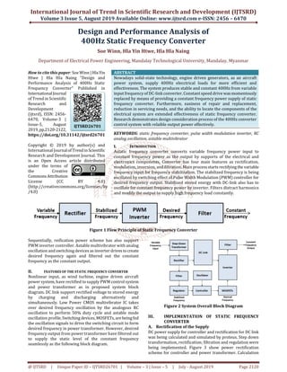
Nowadays solid state technology, engine driven generators, as an aircraft power system, supply 400Hz elecctrical loads for more efficient and effectiveness. The system produces stable and constant 400Hz from variable input frequency of DC link converter. Constant speed drive was momentously replaced by means of providing a constant frequency power supply of static frequency converter. Furthermore, easiness of repair and replacement, reduction in servicing needs, and the ability to locate the components of the electrical system are extended effectiveness of static frequency converter. Research demonstrates design consideration process of the 400Hz converter control system with relaible output power effectively. Soe Winn | Hla Yin Htwe | Hla Hla Naing "Design and Performance Analysis of 400Hz Static Frequency Converter" Published in International Journal of Trend in Scientific Research and Development (ijtsrd), ISSN: 2456-6470, Volume-3 | Issue-5 , August 2019, URL: https://www.ijtsrd.com/papers/ijtsrd26701.pdfPaper URL: https://www.ijtsrd.com/engineering/electrical-engineering/26701/design-and-performance-analysis-of-400hz-static-frequency-converter/soe-winn
2. International Journal of Trend in Scientific Research and Development (IJTSRD) @ www.ijtsrd.com eISSN: 2456-6470
@ IJTSRD | Unique Paper ID – IJTSRD26701 | Volume – 3 | Issue – 5 | July - August 2019 Page 2121
and evaluation of transformer is out of the scope and have
used two winding step down transformer with rating of
220/24V, primary and secondary, inductances and
resistances are 1H and 1mΩ with ideal coupling factor.
Uncontrolled rectifier is being used 4 numbers of 1N4007
take over full wave bridge rectification. Ripple cancellation
feature is implemented by 1mF electrolyte capacitor.
Stabilized output is evaluated and being used 12V battery as
a DC link energy storage device. Voltage regulator as
LM7805 IC with reliable ventilation system, heat sink with
suitable area, should be used as a linear regulator for stable
input to control system. Power transformer is supplied
directly from DC link battery with PWM inverter.
Figure3 Power Rectification Scheme
B. Reference Frequency Oscillation
Linear Regulator LM7805 regulated power to supply CMOS
IC CD4047 which was being used for frequency oscillator
and RC analog oscillation method drives the desired
frequency 400Hz. CD4047 is low power CMOS IC with
monostable/astable multivibrator and configured asastable
function with 50% duty cycle. Trial and error method was
used for R1C1 evaluation by using thefrequencymodulation
formula of astable multivibrator, T = 4.4 R1C1 which drive to
calculate f*R1C1 = 0.227. 100KΩ and 0.022uF or 25KΩ and
20.2nF can use to retrieve 400Hz reference frequencies.
Error accuracy is acceptable and Resistor, Capacitor
evaluation is being implemented.
Figure4 Analog RC Oscillation Scheme
Astable mode pin assignments for CD 4047 IC, figure 4, are
as follows: Pin 4, 5 and 6 as signals input terminals, Pin 8, 9,
12 as neutral or negative rail, Pin 10, 11 as positive and
negative half each oscillators, 1, 2 and 3 as analog oscillation
component, RC, terminals. Pin 13 as NC and Pin 7 and 14 are
power input terminals. According to the performance
analysis result, frequency deviations tolerance is ±1%
(397Hz-403Hz) accurate level.
C. PWM Inverter Switching
Pin 10 and 11, CD 4047 CMOS IC, provide astablemode,50%
duty cycle, positive and negative half pulse-width
modulation signals for oscillation power switching of power
transformer.
Mid-range Mosfet IRFZ44Esarebeingdeployed asfrequency
switching device for PWM inverter switching controller to
achieve desired frequency oscillation. Advantageous of
IRFZ44E are its fast switching and dynamic dv/dt ratingand
also have good switching performance even high
temperature.
Figure5 High Frequency Switching Devices Scheme
Two bleeder resistors are used to limitthecontrolcurrentto
activate the positive and negative sequence alternatively.
According to the characteristic of IRFZ44E, 100KΩ could
limit IGSS would not be greater than maximum drain to
source leakage current with the gate tosource voltage, VGS=
±20V. IRFZ44E have 60ns rise time, ‘Tr’ and 70ns fall time,
‘Tf’ according to datasheet. At the desired frequency 400Hz,
‘f’, the time taken for each positive and negative half cycle is,
T = 1/f = 2.5ms. Sinusoidal alternating voltage must be 50%
duty cycle and could yield positive region on-time,‘Ton’, and
off-time, ‘Toff’, negative region on-time, ‘Ton’, and off-time,
‘Toff’ all are the same length, but symmetrically. Therefore,T
= Ton + Toff + Tr + Tf, could determine on and off duration of
the desired frequency. Ton = Toff = (T – Tr – Tf)/2 =
1.2499ms. Calculation have 0.1us deviation and during
acceptable limit.
Stabilized power from DC link connects directly to power
transformer for power alternation. Power quality is being
acceptable without capacitivefilteringontheprimarysideof
the transformer. Rating of 12/220V center-tap step-up
transformer must be used to achieve each half cycle
oscillation alternatively. The high voltage winding
characteristics are 1H inductance and 15Ω resistance. Low
voltage windings have 0.1Ω copper resistance each and
coupling coefficient is assumed as 0.98.
Figure6 PWM Input and Filterless Output Waveform
Although power transformer output is acceptable modified
sine wave, output waveform has harmonics, dc-offset and
notching which affect the output power quality. Figure 6