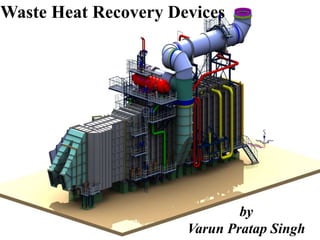
Waste Heat Recovery Devices by Varun Pratap Singh

Download Link (Copy URL): https://sites.google.com/view/varunpratapsingh/teaching-engagements Syllabus: Availability and Irreversibility Availability Function Second Law Efficiencies Work Potential Associated with Internal Energy Waste Heat Recovery Heat Losses – Quality vs. Quantity Principle of Heat Recovery Units Classification of WHRS on Temperature Range Bases Commercial Viable Waste Heat Recovery Devices Benefits of Waste Heat Recovery Development of a Waste Heat Recovery System Commercial Waste Heat Recovery Devices West Heat Recovery Boiler (WHRB) Recuperators- Regenerative, Ceramic, Regenerative Heat Exchanger Thermal wheel/ Heat Wheel Heat Pipe Economiser Feed Water Heat Pump Shell and Tube Heat Exchanger Plate Heat Exchanger Run-around coil Direct Contact Heat Exchanger Advantages and Limitations of WHRD’s

Recomendados
Más contenido relacionado
La actualidad más candente
La actualidad más candente (20)
Similar a Waste Heat Recovery Devices by Varun Pratap Singh
Similar a Waste Heat Recovery Devices by Varun Pratap Singh (20)
Más de Varun Pratap Singh
Más de Varun Pratap Singh (20)
Último
Último (20)
Waste Heat Recovery Devices by Varun Pratap Singh
- 1. Waste Heat Recovery Devices by Varun Pratap Singh
- 2. CONTENT • Availability and Irreversibility • Availability Function • Second Law Efficiencies • Work Potential Associated with Internal Energy • Waste Heat Recovery • Heat Losses – Quality vs. Quantity • Principle of Heat Recovery Units • Classification of WHRS on Temperature Range Bases • Commercial Viable Waste Heat Recovery Devices • Benefits of Waste Heat Recovery • Development of a Waste Heat Recovery System • Commercial Waste Heat Recovery Devices • West Heat Recovery Boiler (WHRB) • Recuperators- Regenerative, Ceramic, Regenerative Heat Exchanger • Thermal wheel/ Heat Wheel • Heat Pipe • Economiser • Feed Water • Heat Pump • Shell and Tube Heat Exchanger • Plate Heat Exchanger • Run-around coil • Direct Contact Heat Exchanger • Advantages and Limitations of WHRD’s
- 3. Availability and Irreversibility Available and Unavailable Energy The second law of thermodynamics tells us that it is not possible to convert all the heat absorbed by a system into work. Suppose a certain quantity of energy Q as heat can be received from a body at temperature T. The maximum work can be obtained by operating a Carnot engine (reversible engine) using the body at T as the source and the ambient atmosphere at T0 as the sink. Where Ds is the entropy of the body supplying the energy as heat. The Carnot cycle and the available energy is shown in figure. The area 1-2-3-4 represents the available energy.
- 4. Suppose a finite body is used as a source. Let a large number of differential Carnot engines be used with the given body as the source. If the initial and final temperatures of the source are T1 and T2respectively, the total work done or the available energy is given by The shaded area 4-3-B-A represents the energy, which is discarded to the ambient atmosphere, and this quantity of energy cannot be converted into work and is called Unavailable energy.
- 5. Loss in Available Energy Suppose a certain quantity of energy Q is transferred from a body at constant temperature T1 to another body at constant temperature T2 (T2<T1). Initial available energy, with the body at T1, Final available energy, with the body at T2, Loss in available energy where Dsuni is the change in the entropy of the universe.
- 6. Availability Function The availability of a given system is defined as the maximum useful work that can be obtained in a process in which the system comes to equilibrium with the surroundings or attains the dead state. (a) Availability Function for Non-Flow process:- Let P0 be the ambient pressure, V1 and V0 be the initial and final volumes of the system respectively. If in a process, the system comes into equilibrium with the surroundings, the work done in pushing back the ambient atmosphere is P0(V0-V1). Availability= Wuseful=Wmax-P0(V0-V1) Consider a system which interacts with the ambient at T0. Then, Wmax=(U1-U0)-T0(S1-S0) Availability= Wuseful=Wmax-P0(V0-V1) = ( U1-T0 S1)- ( U0-T0 S0)- P0(V0-V1) = ( U1+ P0V1-T0 S1)- ( U0+P0V0-T0 S0) = f1-f0 where f=U+P0V-T0S is called the availability function for the non-flow process. Thus, the availability: f1-f0. If a system undergoes a change of state from the initial state 1 (where the availability is (f1-f0) to the final state 2 (where the availability is (f2-f0), the change in the availability or the change in maximum useful work associated with the process, is f1-f2.
- 7. (b) Availability Function for Flow process:- The maximum power that can be obtained in a steady flow process while the control volume exchanges energy as heat with the ambient at T0, is given by: Sometimes the availability for a flow process is written as: which is called the Darrieus Function. Availability Function
- 8. Second Law Efficiencies The second law efficiency (h2) of a process, h2=Change in the available energy of the system Change in the available energy of the source (a) Compressors and Pumps:- Change in the availability of the system is given by: where T0 is the ambient temperature The second law efficiency of a compressor or pump is given by,
- 9. (b) Turbines and Expanders:- The change in the available energy of the system=W The change in the available energy of the source=Wrev=B1-B2 The second law efficiency of the turbine h2T/E is given by, Second Law Efficiencies
- 10. Work Potential Associated with Internal Energy The total useful work delivered as the system undergoes a reversible process from the given state to the dead state (that is when a system is in thermodynamic equilibrium with the environment), which is Work potential by definition. Work Potential = Wuseful= Wmax- P0(V0-V1) = ( U1-T0 S1)- ( U0-T0 S0)- P0(V0-V1) = ( U1+ P0V1-T0 S1)- ( U0+P0V0-T0 S0) = f1-f0 The work potential of internal energy (or a closed system) is either positive or zero. It is never negative.
- 11. Work Potential Associated with Enthalpy, h The work potential associated with enthalpy is simply the sum of the energies of its components. The useful work potential of Enthalpy can be expressed on a unit mass basis as: here h0 and s0 are the enthalpy and entropy of the fluid at the dead state. The work potential of enthalpy can be negative at sub atmospheric pressures.
- 12. Waste Heat Recovery • Introduction A waste heat recovery unit (WHRU) isan energy recovery heat exchanger that transfers heat from process outputs at high temperature to another part of the process for some purpose, usually increased efficiency. The WHRU is a tool involved in cogeneration. Waste heat may be extracted from sources such as hot flue gases from a diesel generator, steam from cooling towers, or even waste water from cooling processes such as in steel cooling. Waste heat is heat, which is generated in a process by way of fuel combustion or chemical reaction, and then “dumped” into the environment even though it could still be reused for some useful and economic purpose. The essential quality of heat is not the amount but rather its “value”. The strategy of how to recover this heat depends in part on the temperature of the waste heat gases and the economics involved. Large quantity of hot flue gases is generated from Boilers, Kilns, Ovens and Furnaces. If some of this waste heat could be recovered, a considerable amount of primary fuel could be saved. The energy lost in waste gases cannot be fully recovered. However, much of the heat could be recovered and loss minimized by adopting following measures as outlined in this chapter.
- 13. Heat Losses – Quality vs. Quantity • Heat Losses – Quality Depending upon the type of process, waste heat can be rejected at virtually any temperature from that of chilled cooling water to high temperature waste gases from an industrial furnace or kiln. Usually higher the temperature, higher the quality and more cost effective is the heat recovery. In any study of waste heat recovery, it is absolutely necessary that there should be some use for the recovered heat. Typical examples of use would be preheating of combustion air, space heating, or pre-heating boiler feed water or process water. With high temperature heat recovery, a cascade system of waste heat recovery may be practiced to ensure that the maximum amount of heat is recovered at the highest potential. An example of this technique of waste heat recovery would be where the high temperature stage was used for air pre-heating and the low temperature stage used for process feed water heating or steam raising. Heat Losses – Quantity In any heat recovery situation it is essential to know the amount of heat recoverable and also how it can be used. An example of the availability of waste heat is given below: • Heat recovery from heat treatment furnace In a heat treatment furnace, the exhaust gases are leaving the furnace at 900 °C at the rate ofv2100 m3/hour. The total heat recoverable at 180oC final exhaust can be calculated as Q = V × ρ × Cp × ∆T ; where Q is the heat content in kCal and V is the flowrate of the substance in m3/hr ρ is density of the flue gas in kg/m3, Cvp is the specific heat of the substance in kCal/kg °C ∆T is the temperature difference in °C and Cp (Specific heat of flue gas) = 0.24 kCal/kg/°C Heat available (Q) = 2100 × 1.19 × 0.24 × ((900-180) = 4,31,827 kCal/hr By installing a recuperator, this heat can be recovered to pre-heat the combustion air. The fuel savings would be 33% (@ 1% fuel reduction for every 22 °C reduction in temperature of flue gas
- 14. Principle of Heat Recovery Units • Waste heat found in the exhaust gas of various processes or even from the exhaust stream of a conditioning unit can be used to preheat the incoming gas. This is one of the basic methods for recovery of waste heat. Many steel making plants use this process as an economic method to increase the production of the plant with lower fuel demand.
- 15. Classification of WHRS on Temperature Range Bases High Temperature Heat Recovery The following Table 8.2 gives temperatures of waste gases from industrial process equipment in the high temperature range. All of these results from direct fuel fired processes. Medium Temperature Heat Recovery The following Table 8.3 gives the temperatures of waste gases from process equipment in the medium temperature range. Most of the waste heat in this temperature range comes from the exhaust of directly fired process units. Low Temperature Heat Recovery The following Table 8.4 lists some heat sources in the low temperature range. In this range it is usually not practical to extract work from the source, though steam production may not be completely excluded if there is a need for low- pressure steam. Low temperature waste heat may be useful in a supplementary way for preheating purposes.
- 16. Classification of WHRS on Temperature Range Bases Low Temperature Heat Recovery The following Table 8.4 lists some heat sources in the low temperature range. In this range it is usually not practical to extract work from the source, though steam production may not be completely excluded if there is a need for low- pressure steam. Low temperature waste heat may be useful in a supplementary way for preheating purposes.
- 17. • There are many different commercial recovery units for the transferring of energy from hot medium space to lower one: • Recuperators: This name is given to different types of heat exchanger that the exhaust gases are passed through, consisting of metal tubes that carry the inlet gas and thus preheating the gas before entering the process. The heat wheel is an example which operates on the same principle as a solar air conditioning unit. • Regenerators: This is an industrial unit that reuses the same stream after processing. In this type of heat recovery, the heat is regenerated and reused in the process. • Heat pipe exchanger: Heat pipes are one of the best thermal conductors. They have the ability to transfer heat hundred times more than copper. Heat pipes are mainly known in renewable energy technology as being used in evacuated tube collectors. The heat pipe is mainly used in space, process or air heating, in waste heat from a process is being transferred to the surrounding due to its transfer mechanism. • Thermal Wheel or rotary heat exchanger: consists of a circular honeycomb matrix of heat absorbing material, which is slowly rotated within the supply and exhaust air streams of an air handling system. • Economizer: In case of process boilers, waste heat in the exhaust gas is passed along a recuperators that carries the inlet fluid for the boiler and thus decreases thermal energy intake of the inlet fluid. Classification of WHRS on basis of Type of Equipment's
- 18. • Heat pumps: Using an organic fluid that boils at a low temperature means that energy could be regenerated from waste fluids. • Run around coil: comprises two or more multi-row finned tube coils connected to each other by a pumped pipework circuit. Classification of WHRS on basis of Type of Equipment's
- 19. Benefits of Waste Heat Recovery Benefits of 'waste heat recovery' can be broadly classified in two categories: • Direct Benefits: Recovery of waste heat has a direct effect on the efficiency of the process. This is reflected by reduction in the utility consumption & costs, and process cost. • Indirect Benefits: a) Reduction in pollution: A number of toxic combustible wastes such as carbon monoxide gas, sour gas, carbon black off gases, oil sludge, Acrylonitrile and other plastic chemicals etc., releasing to atmosphere if/when burnt in the incinerators serves dual purpose i.e. recovers heat and reduces the environmental pollution levels. b) Reduction in equipment sizes: Waste heat recovery reduces the fuel consumption, which leads to reduction in the flue gas produced. This results in reduction in equipment sizes of all flue gas handling equipment's such as fans, stacks, ducts, burners, etc. c) Reduction in auxiliary energy consumption: Reduction in equipment sizes gives additional benefits in the form of reduction in auxiliary energy consumption like electricity for fans, pumps etc..
- 20. Development of a Waste Heat Recovery System Understanding the process Understanding the process is essential for development of Waste Heat Recovery system. This can be accomplished by reviewing the process flow sheets, layout diagrams, piping isometrics, electrical and instrumentation cable ducting etc. Detail review of these documents will help in identifying: a) Sources and uses of waste heat b) Upset conditions occurring in the plant due to heat recovery c) Availability of space d) Any other constraint, such as dew point occurring in an equipment's etc. After identifying source of waste heat and the possible use of it, the next step is to select suitable heat recovery system and equipment's to recover and utilise the same. Economic Evaluation of Waste Heat Recovery System It is necessary to evaluate the selected waste heat recovery system on the basis of financial analysis such as investment, depreciation, payback period, rate of return etc. In addition the advice of experienced consultants and suppliers must be obtained for rational decision. Next section gives a brief description of common heat recovery devices available commercially and its typical industrial applications.
- 21. Commercial Waste Heat Recovery Devices 1. Waste Heat Recovery Boilers 2. Recuperators a) Radiation/Convective Hybrid Recuperator: b) Ceramic Recuperator 3. Regenerators 4. Heat pipe exchanger 5. Thermal Wheel 6. Economizer a) Shell and Tube Heat Exchanger b) Plate heat exchanger 7. Heat pumps 8. Heat Wheels 9. Heat Pipe 10. Run Around Coil Exchanger 11. Thermo-compressor 12. Direct Contact Heat Exchanger a) Hot-Hot mixing b) Different Phase mixing c) Hot-Cold Mixing
- 22. waste heat recovery boiler (WHRB) West Heat Recovery Boiler (WHRB)
- 23. West Heat Recovery Boiler (WHRB) Fig: Schematic Diagram of WHRB system in Combine Cycle Power Plant
- 24. • Waste heat boilers are ordinarily water tube boilers in which the hot exhaust gases from gas turbines, incinerators, etc., pass over a number of parallel tubes containing water. The water is vaporized in the tubes and collected in a steam drum from which it is drawn off for use as heating or processing steam. • Because the exhaust gases are usually in the medium temperature range and in order to conserve space, a more compact boiler can be produced if the water tubes are finned in order to increase the effective heat transfer area on the gas side. The Figure 8.11 shows a mud drum, a set of tubes over which the hot gases make a double pass, and a steam drum which collects steam generated above the water surface. The pressure at which the steam is generated and the rate of steam production depends on the temperature of waste heat. The pressure of a pure vapour in the presence of its liquid is a function of the temperature of the liquid from which it is evaporated. The steam tables tabulate this relationship between saturation pressure and temperature. • If the waste heat in the exhaust gases is insufficient for generating the required amount of process steam, auxiliary burners which burn fuel in the waste heat boiler or an after-burner in the exhaust gases flue are added. Waste heat boilers are built in capacities from 25 m3 almost 30,000 m3 / min. of exhaust gas. West Heat Recovery Boiler (WHRB)
- 25. Recuperators • Recuperators is a special purpose counter-flow energy recovery heat exchanger positioned within the supply and exhaust air streams of an air handling system, or in the exhaust gases of an industrial process, in order to recover the waste heat. Generally, they are used to extract heat from the exhaust and use it to preheat air entering the combustion system. In this way they use waste energy to heat the air, offsetting some of the fuel, and thereby improves the energy efficiency of the system as a whole. • In a recuperator, heat exchange takes place between the flue gases and the air through metallic or ceramic walls. Duct or tubes carry the air for combustion to be pre-heated, the other side contains the waste heat stream. A recuperator for recovering waste heat from flue gases is shown • in Figure, The simplest configuration for a recuperator is the metallic radiation recuperator, which consists of two concentric lengths of metal tubing as shown in Figure 8.2. The inner tube carries the hot exhaust gases while the external annulus carries the combustion air from the atmosphere to the air inlets of the furnace burners. The hot gases are cooled by the incoming combustion air which now carries additional energy into the combustion chamber. This is energy which does not have to be supplied by the fuel; consequently, less fuel is burned for a given furnace loading. The saving in fuel also means a decrease in combustion air and therefore stack losses are decreased not only by lowering • the stack gas temperatures but also by discharging smaller quantities of exhaust gas.
- 26. • The radiation recuperator gets its name from the fact that a substantial portion of the heat transfer from the hot gases to the surface of the inner tube takes place by radiative heat transfer. The cold air in the annuals, however, is almost transparent to infrared radiation so that only convection heat transfer takes place to the incoming air. As shown in the diagram, the two gas flows are usually parallel, although the configuration would be simpler and the heat transfer more efficient if the flows were opposed in direction (or counter flow). The reason for the use of parallel flow is that recuperators frequently serve the additional function of cooling the duct carrying away the exhaust gases and consequently extending its service life. Radiative Recuperators
- 27. • A second common configuration for recuperators is called the tube type or convective recuperator. As seen in the figure 8.3, the hot gases are carried through a number of parallel small diameter tubes, while the incoming air to be heated enters a shell surrounding the tubes and passes over the hot tubes one or more times in a direction normal to their axes. If the tubes are baffled to allow the gas to pass over them twice, the heat exchanger is termed a two-pass recuperator; if two baffles are used, a three- pass recuperator, etc. Although baffling increases both the cost of the exchanger and the pressure drop in the combustion air path, it increases the effectiveness of heat exchange. Shell and tube type recuperators are generally more compact and have a higher effectiveness than radiation recuperators, because of the larger heat transfer area made possible through the use of multiple tubes and multiple passes of the gases. Radiative Recuperators
- 28. • Radiation/Convective Hybrid Recuperator: For maximum effectiveness of heat transfer, combinations of radiation and convective designs are used, with the high-temperature radiation recuperator being first followed by convection type. These are more expensive than simple metallic radiation recuperators, but are less bulky. A Convective/radiative Hybrid recuperator is shown in Figure Radiation/Convective Hybrid Recuperators
- 29. • The principal limitation on the heat recovery of metal recuperators is the reduced life of the liner at inlet temperatures exceeding 1100°C. In order to overcome the temperature limitations of metal recuperators, ceramic tube recuperators have been developed whose materials allow operation on the gas side to 1550°C and on the preheated air side to 815°C on a more or less practical basis. Early ceramic recuperators were built of tile and joined with furnace cement, and thermal cycling caused cracking of joints and rapid deterioration of the tubes. Later developments introduced various kinds of short silicon carbide tubes which can be joined by flexible seals located in the air headers. • Earlier designs had experienced leakage rates from 8 to 60 percent. The new designs are reported to last two years with air preheat temperatures as high as 700°C, with much lower leakage rates. • Ceramic Recuperators
- 30. Recuperators can be used to increase the efficiency of gas turbines for power generation, provided the exhaust gas is hotter than the compressor outlet temperature. The exhaust heat from the turbine is used to pre-heat the air from the compressor before further heating in the combustor, reducing the fuel input required. The larger the temperature difference between turbine out and compressor out, the greater the benefit from the recuperator. Therefore, micro turbines (<1MW), which typically have low pressure ratios, have the most to gain from the use of a recuperator. In practice, a doubling of efficiency is possible through the use of a recuperator. The major practical challenge for a recuperator in micro turbine applications is coping with the exhaust gas temperature, which can exceed 750 °C (1,380 °F).
- 31. Regenerative Heat Exchanger • A regenerative heat exchanger, or more commonly a regenerator, is a type of heat exchanger where heat from the hot fluid is intermittently stored in a thermal storage medium before it is transferred to the cold fluid. To accomplish this the hot fluid is brought into contact with the heat storage medium, then the fluid is displaced with the cold fluid, which absorbs the heat. • In regenerative heat exchangers, the fluid on either side of the heat exchanger can be the same fluid. The fluid may go through an external processing step, and then it is flowed back through the heat exchanger in the opposite direction for further processing. Usually the application will use this process cyclically or repetitively. • Regenerative heating was one of the most important technologies developed during the Industrial Revolution when it was used in the hot blast process on blast furnaces, It was later used in glass and steel making, to increase the efficiency of open hearth furnaces, and in high pressure boilers and chemical and other applications, where it continues to be important today. • The Regeneration which is preferable for large capacities has been very widely used in glass and steel melting furnaces. Important relations exist between the size of the regenerator, time between reversals, thickness of brick, conductivity of brick and heat storage ratio of the brick. • In a regenerator, the time between the reversals is an important aspect. Long periods would mean higher thermal storage and hence higher cost. Also long periods of reversal result in lower average temperature of preheat and consequently reduce fuel economy. (Refer Figure 8.5). • Accumulation of dust and slagging on the surfaces reduce efficiency of the heat transfer as the furnace becomes old. • Heat losses from the walls of the regenerator and air in leaks during the gas period and out leaks during air period also reduces the heat transfer.
- 32. Thermal wheel/ Heat Wheel • A thermal wheel, also known as a rotary heat exchanger, or rotary air-to-air enthalpy wheel, or heat recovery wheel, is a type of energy recovery heat exchanger positioned within the supply and exhaust air streams of an air-handling system or in the exhaust gases of an industrial process, in order to recover the heat energy. Other variants include enthalpy wheels and desiccant wheels. A cooling-specific thermal wheel is sometimes referred to as a Kyoto wheel.
- 34. Case Examples for Heat Wheel • Case Example:1 A rotary heat regenerator was installed on a two colour printing press to recover some of the heat, which had been previously dissipated to the atmosphere, and used for drying stage of the process. The outlet exhaust temperature before heat recovery was often in excess of 100°C. After heat recovery the temperature was 35°C. Percentage heat recovery was 55% and payback on the investment was estimated to be about 18 months. Cross contamination of the fresh air from the solvent in the exhaust gases was at a very acceptable level. • Case Example:2 A ceramic firm installed a heat wheel on the preheating zone of a tunnel kiln where 7500 m3/hour of hot gas at 300°C was being rejected to the atmosphere. The result was that the flue gas temperature was reduced to 150°C and the fresh air drawn from the top of the kiln was preheated to 155°C. The burner previously used for providing the preheated air was no longer required. The capital cost of the equipment was recovered in less than 12 months.
- 35. Heat Pipe • A heat pipe is a heat-transfer device that combines the principles of both thermal conductivity and phase transition to effectively transfer heat between two solid interfaces. • A heat pipe can transfer up to 100 times more thermal energy than copper, the best known conductor. In other words, heat pipe is a thermal energy absorbing and transferring system and have no moving parts and hence require minimum maintenance. • At the hot interface of a heat pipe a liquid in contact with a thermally conductive solid surface turns into a vapor by absorbing heat from that surface. The vapor then travels along the heat pipe to the cold interface and condenses back into a liquid – releasing the latent heat. The liquid then returns to the hot interface through either capillary action, centrifugal force, or gravity, and the cycle repeats. Due to the very high heat transfer coefficients for boiling and condensation, heat pipes are highly effective thermal conductors. The effective thermal conductivity varies with heat pipe length, and can approach 100 kW/(m⋅K) for long heat pipes, in comparison with approximately 0.4 kW/(m⋅K) for copper.
- 36. Heat Pipe Mechanism Figure: Heat Pipe
- 37. • The Heat Pipe comprises of three elements - a sealed container, a capillary wick structure and a working fluid. The capillary wick structure is integrally fabricated into the interior surface of the container tube and sealed under vacuum. Thermal energy applied to the external surface of the heat pipe is in equilibrium with its own vapour as the container tube is sealed under vacuum. Thermal energy applied to the external surface of the heat pipe causes the working fluid near the surface to evaporate instantaneously. Vapour thus formed absorbs the latent heat of vaporisation and this part of the heat pipe becomes an evaporator region. The vapour then travels to the other end the pipe where the thermal energy is removed causing the vapour to condense into liquid again, thereby giving up the latent heat of the condensation. This part of the heat pipe works as the condenser region. The condensed liquid then flows back to the evaporated region. A figure of Heat pipe is shown in Figure 8.7 • Performance and Advantage The heat pipe exchanger (HPHE) is a lightweight compact heat recovery system. It virtually does not need mechanical maintenance, as there are no moving parts to wear out. It does not need input power for its operation and is free from cooling water and lubrication systems. It also lowers the fan horsepower requirement and increases the overall thermal efficiency of the system. The heat pipe heat recovery systems are capable of operating at 315°C. with 60% to 80% heat recovery capability. Heat Pipe
- 38. Structure, Design and Construction • A typical heat pipe consists of a sealed pipe or tube made of a material that is compatible with the working fluid such as copper for water heat pipes, or aluminium for ammonia heat pipes. Typically, a vacuum pump is used to remove the air from the empty heat pipe. The heat pipe is partially filled with a working fluid and then sealed. The working fluid mass is chosen so that the heat pipe contains both vapour and liquid over the operating temperature range. • Below the operating temperature, the liquid is too cold and cannot vaporize into a gas. Above the operating temperature, all the liquid has turned to gas, and the environmental temperature is too high for any of the gas to condense. Whether too high or too low, thermal conduction is still possible through the walls of the heat pipe, but at a greatly reduced rate of thermal transfer. • Structure, Design and Construction • A typical heat pipe consists of a sealed pipe or tube made of a material that is compatible with the working fluid such as copper for water heat pipes, or aluminium for ammonia heat pipes. Typically, a vacuum pump is used to remove the air from the empty heat pipe. The heat pipe is partially filled with a working fluid and then sealed. The working fluid mass is chosen so that the heat pipe contains both vapour and liquid over the operating temperature range. • Below the operating temperature, the liquid is too cold and cannot vaporize into a gas. Above the operating temperature, all the liquid has turned to gas, and the environmental temperature is too high for any of the gas to condense. Whether too high or too low, thermal conduction is still possible through the walls of the heat pipe, but at a greatly reduced rate of thermal transfer.
- 39. Heat Pipe Materials and Working Fluids • Heat pipes have an envelope, a wick, and a working fluid. Heat pipes are designed for very long term operation with no maintenance, so the heat pipe wall and wick must be compatible with the working fluid. Some material/working fluids pairs that appear to be compatible are not. For example, water in an aluminum envelope will develop large amounts of non-condensable gas over a few hours or days, preventing normal operation of the heat pipe. • Since heat pipes were rediscovered by George Grover in 1963, extensive life tests have been conducted to determine compatible envelope/fluid pairs, some going on for decades. In a heat pipe life test, heat pipes are operated for long periods of time, and monitored for problems such as non-condensable gas generation, material transport, and corrosion. • The most commonly used envelope (and wick)/fluid pairs include:[ • Copper envelope with water working fluid for electronics cooling. This is by far the most common type of heat pipe. • Copper or steel envelope with refrigerant R134a working fluid for energy recovery in HVAC systems. • Aluminium envelope with ammonia working fluid for Spacecraft Thermal Control. • Super alloy envelope with alkali metal (cesium, potassium, sodium) working fluid for high temperature heat pipes, most commonly used for calibrating primary temperature measurement devices. • Other pairs include stainless steel envelopes with nitrogen, oxygen, neon, hydrogen, or helium working fluids at temperatures below 100 K, copper/methanol heat pipes for electronics cooling when the heat pipe must operate below the water range, aluminium/ethane heat pipes for spacecraft thermal control in environments when ammonia can freeze, and refractory metal envelope/lithium working fluid for high temperature (above 1,050 °C (1,920 °F)) applications.
- 40. Different Types of Heat Pipes • In addition to standard, Constant Conductance Heat Pipes (CCHPs), there are a number of other types of heat pipes, including: • Vapour Chambers (planar heat pipes), which are used for heat flux transformation, and isothermalization of surfaces • Variable Conductance Heat Pipes (VCHPs), which use a Non-Condensable Gas (NCG) to change the heat pipe effective thermal conductivity as power or the heat sink conditions change • Pressure Controlled Heat Pipes (PCHPs), which are a VCHP where the volume of the reservoir, or the NCG mass can be changed, to give more precise temperature control • Diode Heat Pipes, which have a high thermal conductivity in the forward direction, and a low thermal conductivity in the reverse direction • Thermosyphons, which are heat pipes where the liquid is returned to the evaporator by gravitational/accelerational forces, • Rotating heat pipes, where the liquid is returned to the evaporator by centrifugal forces
- 41. Applications • Spacecraft • The spacecraft thermal control system has the function to keep all components on the spacecraft within their acceptable temperature range. This is complicated by the following: • Widely varying external conditions, such as eclipses Micro-g environment Heat removal from the spacecraft by thermal radiation only Limited electrical power available, favouring passive solutions Long lifetimes, with no possibility of maintenance Some spacecraft are designed to last for 20 years, so heat transport without electrical power or moving parts is desirable. Rejecting the heat by thermal radiation means that large radiator panes (multiple square meters) are required. Heat pipes and loop heat pipes are used extensively in spacecraft, since they don’t require any power to operate, operate nearly isothermally, and can transport heat over long distances. • Grooved wicks are used in spacecraft heat pipes, as shown in the first photograph in this section. The heat pipes are formed by extruding aluminium, and typically have an integral flange to increase the heat transfer area, which lowers the temperature drop. Grooved wicks are used in spacecraft, instead of the screen or sintered wicks used for terrestrial heat pipes, since the heat pipes don’t have to operate against gravity in space. This allows spacecraft heat pipes to be several meters long, in contrast to the roughly 25 cm maximum length for a water heat pipe operating on Earth. Ammonia is the most common working fluid for spacecraft heat pipes. Ethane is used when the heat pipe must operate at temperatures below the ammonia freezing temperature. • The second figure shows a typical grooved aluminium/ammonia Variable Conductance Heat Pipe (VCHP) for spacecraft thermal control. The heat pipe is an aluminium extrusion, similar to that shown in the first figure. The bottom flanged area is the evaporator. Above the evaporator, the flange is machined off to allow the adiabatic section to be bent. The condenser is shown above the adiabatic section. The Non-Condensable Gas (NCG) reservoir is located above the main heat pipe. The valve is removed after filling and sealing the heat pipe. When electric heaters are used on the reservoir, the evaporator temperature can be controlled within ±2 K of the set point. • Computer systems • Heat pipes began to be used in computer systems in the late 1990s, when increased power requirements and subsequent increases in heat emission resulted in greater demands on cooling systems. They are now extensively used in many modern computer systems, typically to move heat away from components such as CPUs and GPUs to heat sinks where thermal energy may be dissipated into the environment.
- 42. Solar thermal Heat pipes are also widely used in solar thermal water heating applications in combination with evacuated tube solar collector arrays. In these applications, distilled water is commonly used as the heat transfer fluid inside a sealed length of copper tubing that is located within an evacuated glass tube and oriented towards the sun. In connecting pipes, the heat transport occurs in the liquid steam phase because the thermal transfer medium is converted into steam in a large section of the collecting pipeline. Permafrost cooling Alaska pipeline support legs cooled by heat pipe thermosyphons to keep permafrost frozen Building on permafrost is difficult because heat from the structure can thaw the permafrost. Heat pipes are used in some cases to avoid the risk of destabilization. For example, in the Trans-Alaska Pipeline System residual ground heat remaining in the oil as well as heat produced by friction and turbulence in the moving oil could conduct down the pipe's support legs and melt the permafrost on which the supports are anchored. This would cause the pipeline to sink and possibly be damaged. To prevent this, each vertical support member has been mounted with four vertical heat pipe thermosyphons. Applications
- 43. Cooking The first commercial heat pipe product was the "Thermal Magic Cooking Pin" developed by Energy Conversion Systems, Inc. and first sold in 1966. The cooking pins used water as the working fluid. The envelope was stainless steel, with an inner copper layer for compatibility. During operation, one end of the heat pipe is poked through the roast. The other end extends into the oven where it draws heat to the middle of the roast. The high effective conductivity of the heat pipe reduces the cooking time for large pieces of meat by one-half. Alaska pipeline support legs cooled by heat pipe thermosyphons to keep permafrost frozen Ventilation heat recovery In heating, ventilation and air-conditioning systems, HVAC, heat pipes are positioned within the supply and exhaust air streams of an air handling system or in the exhaust gases of an industrial process, in order to recover the heat energy. Nuclear power conversion Grover and his colleagues were working on cooling systems for nuclear power cells for space craft, where extreme thermal conditions are encountered. These alkali metal heat pipes transferred heat from the heat source to a thermionic or thermoelectric converter to generate electricity. Nuclear power conversion Grover and his colleagues were working on cooling systems for nuclear power cells for space craft, where extreme thermal conditions are encountered. These alkali metal heat pipes transferred heat from the heat source to a thermionic or thermoelectric converter to generate electricity. Applications
- 44. Typical Application The heat pipes are used in following industrial applications: a. Process to Space Heating: The heat pipe heat exchanger transfers the thermal energy from process exhaust for building heating. The preheated air can be blended if required. The requirement of additional heating equipment to deliver heated make up air is drastically reduced or eliminated. b. Process to Process: The heat pipe heat exchangers recover waste thermal energy from the process exhaust and transfer this energy to the incoming process air. The incoming air thus become warm and can be used for the same process/other processes and reduces process energy consumption. c. HVAC Applications: Cooling: Heat pipe heat exchangers precools the building make up air in summer and thus reduces the total tons of refrigeration, apart from the operational saving of the cooling system. Thermal energy is supply recovered from the cool exhaust and transferred to the hot supply make up air. Heating: The above process is reversed during winter to preheat the make up air. The other applications in industries are: • Preheating of boiler combustion air • Recovery of Waste heat from furnaces • Reheating of fresh air for hot air driers • Recovery of waste heat from catalytic deodorizing equipment • Reuse of Furnace waste heat as heat source for other oven • Cooling of closed rooms with outside air • Preheating of boiler feed water with waste heat recovery from flue gases in the heat pipe economizers. • Drying, curing and baking ovens • Waste steam reclamation • Brick kilns (secondary recovery) • Reverberator furnaces (secondary recovery) • Heating, ventilating and air-conditioning systems Applications
- 45. Volume Recovered heat Plant capacity reduction Electricity cost (operation) Plant capacity reduction cost (Capital) Capital cost savings Payback period 140 m3/min Exhaust 28225 kCal/hr 9.33 Tons of Refrigeration Rs. 268/Million kCal (based on 0.8 kW/TR) Rs.12,000/TR Rs. 1,12,000/- 16570 hours Case Example of Heat Pipe Savings in Hospital Cooling Systems
- 46. Economizer In boilers, economizers are heat exchange devices that heat fluids, usually water, up to but not normally beyond the boiling point of that fluid. Economizers are so named because they can make use of the enthalpy in fluid streams that are hot, but not hot enough to be used in a boiler, thereby recovering more useful enthalpy and improving the boiler's efficiency. They are a device fitted to a boiler which saves energy by using the exhaust gases from the boiler to preheat the cold water used to fill it (the feed water An economizer serves a similar purpose to a feed water heater, but is technically different as it does not use cycle steam for heating. In fossil-fuel plants, the economizer uses the lowest-temperature flue gas from the furnace to heat the water before it enters the boiler proper. This allows for the heat transfer between the furnace and the feed water to occur across a smaller average temperature gradient (for the steam generator as a whole). System efficiency is therefore further increased when viewed with respect to actual energy content of the fuel. Most nuclear power plants do not have an economizer. However, the Combustion Engineering System 80+ nuclear plant design and its evolutionary successors, (e.g. Korea Electric Power Corporation's APR-1400) incorporate an integral feed water economizer. This economizer preheats the steam generator feed water at the steam generator inlet using the lowest- temperature primary coolant.
- 47. Shell and Tube Heat Exchanger When the medium containing waste heat is a liquid or a vapour which heats another liquid, then the shell and tube heat exchanger must be used since both paths must be sealed to contain the pressures of their respective fluids. The shell contains the tube bundle, and usually internal baffles, to direct the fluid in the shell over the tubes in multiple passes. The shell is inherently weaker than the tubes so that the higher- pressure fluid is circulated in the tubes while the lower pressure fluid flows through the shell. When a vapour contains the waste heat, it usually condenses, giving up its latent heat to the liquid being heated. In this application, the vapour is almost invariably contained within the shell. If the reverse is attempted, the condensation of vapours within small diameter parallel tubes causes flow instabilities. Tube and shell heat exchangers are available in a wide range of standard sizes with many combinations o materials for the tubes and shells. A shell and tube heat exchanger is illustrated in Figure. Typical applications of shell and tube heat exchangers include heating liquids with the heat contained by condensates from refrigeration and air-conditioning systems; condensate from process steam; coolants from furnace doors, grates, and pipe supports; coolants from engines, air compressors, bearings, and lubricants; and the condensates from distillation processes.
- 48. Plate Heat Exchanger • The cost of heat exchange surfaces is a major cost factor when the temperature differences are not large. One way of meeting this problem is the plate type heat exchanger, which consists of a series of separate parallel plates forming thin flow pass. Each plate is separated from the next by gaskets and the hot stream passes in parallel through alternative plates whilst the liquid to be heated passes in parallel between the hot plates. To improve heat transfer the plates are corrugated. • Hot liquid passing through a bottom port in the head is permitted to pass upwards between every second plate while cold liquid at the top of the head is permitted to pass downwards between the odd plates. When the directions of hot & cold fluids are opposite, the arrangement is described as counter current. A plate heat exchanger is shown in Figure 8.10. Typical industrial applications are: – Pasteurisation section in milk packaging plant. – Evaporation plants in food industry.
- 49. Feed Water Heater • A feed water heater is a power plant component used to pre-heat water delivered to a steam generating boiler Preheating the feed water reduces the irreversibilities involved in steam generation and therefore improves the thermodynamic efficiency of the system. This reduces plant operating costs and also helps to avoid thermal shock to the boiler metal when the feed water is introduced back into the steam cycle. • In a steam power plant (usually modelled as a modified Rankine cycle), feed water heaters allow the feed water to be brought up to the saturation temperature very gradually. This minimizes the inevitable irreversibilities associated with heat transfer to the working fluid (water). See the article on the second law of thermodynamics for a further discussion of such irreversibilities. Fig: A Rankine cycle with two steam turbines and a single open feed water heater.
- 50. Application
- 51. Heat Pump • A heat pump is a device that transfers heat energy from a source of heat to what is called a heat sink. Heat pumps move thermal energy in the opposite direction of spontaneous heat transfer, by absorbing heat from a cold space and releasing it to a warmer one. A heat pump uses a small amount of external power to accomplish the work of transferring energy from the heat source to the heat sink. The most common design of a heat pump involves four main components – a condenser, an expansion valve, an evaporator and a compressor. The heat transfer medium circulated through these components is called refrigerant. • While air conditioners and freezers are familiar examples of heat pumps, the term "heat pump" is more general and applies to many HVAC (heating, ventilating, and air conditioning) devices used for space heating or space cooling. When a heat pump is used for heating, it employs the same basic refrigeration-type cycle used by an air conditioner or a refrigerator, but in the opposite direction – releasing heat into the conditioned space rather than the surrounding environment. In this use, heat pumps generally draw heat from the cooler external air or from the ground. • In heating mode, heat pumps are three to four times more effective at heating than simple electrical resistance heaters using the same amount of electricity. However, the typical cost of installing a heat pump is also higher than that of a resistance heater. • When discussing about and comparing energy efficiency of heat pumping applications some different factors are mainly used, COP (Coefficient of Performance), SCOP (Seasonal Coefficient of Performance) and SPF (Seasonal Performance Factor). The more efficient a heat pump is the less energy consuming it will be and the more cost-effective it can be to operate. There are several factors that will affect the efficiency of a heat pump such as climate, temperature, auxiliary equipment, technology, size and control system.
- 52. Applications • There are millions of domestic installations using air source heat pumps. They are used in climates with moderate space heating and cooling needs (HVAC) and may also provide domestic hot water. The purchase costs are supported in various countries by consumer rebates. • HVAC • In HVAC applications, a heat pump is typically a vapuor-compression refrigeration device that includes a reversing valve and optimized heat exchangers so that the direction of heat flow (thermal energy movement) may be reversed. The reversing valve switches the direction of refrigerant through the cycle and therefore the heat pump may deliver either heating or cooling to a building. In cooler climates, the default setting of the reversing valve is heating. • Water heating • In water heating applications, a heat pump may be used to heat or preheat water for swimming pools or heating potable water for use by homes and industry. Usually heat is extracted from outdoor air and transferred to an indoor water tank, another variety extracts heat from indoor air to assist in cooling the space. • District heating • Heat pumps can be integrated in district heating systems, especially if these are operated with low temperatures. • Heat pumps can also be used as heat supplier for district heating. Possible heat sources for such applications are sewage water, ambient water (like sea, lake and river water), industrial waste heat, geothermal energy, flue gas, waste heat from district cooling and heat from solar heat storage. • Industrial heating • There is a great potential to reduce the energy consumption and related greenhouse gas emissions in the industry by application of industrial heat pumps. An international collaboration project completed in 2015 collected totally 39 examples of R&D-projects and 115 case studies worldwide.
- 53. Run-around coil • A run-around coil is a type of energy recovery heat exchanger most often positioned within the supply and exhaust air streams of an air handling system, or in the exhaust gases of an industrial process, to recover the heat energy. Generally, it refers to any intermediate stream used to transfer heat between two streams that are not directly connected for reasons of safety or practicality. It may also be referred to as a run-around loop, a pump-around coil or a liquid coupled heat exchanger. • It is quite similar in principle to the heat pipe exchanger. The heat from hot fluid is transferred to the colder fluid via an intermediate fluid known as the Heat Transfer Fluid. One coil of this closed loop is installed in the hot stream while the other is in the cold stream. Circulation of this fluid is maintained by means of circulating pump. • It is more useful when the hot land cold fluids are located far away from each other and are not easily accessible. Typical industrial applications are heat recovery from ventilation, air conditioning and low temperature heat recovery.
- 54. Thermo-Compressor • In many cases, very low pressure steam are reused as water after condensation for lack of any better option of reuse. In many cases it becomes feasible to compress this low pressure steam by very high pressure steam and reuse it as a medium pressure steam. The major energy in steam, is in its latent heat value and thus thermo-compressing would give a large improvement in waste heat recovery. The thermo-compressor is a simple equipment with a nozzle where HP steam is accelerated into a high velocity fluid. This entrains the LP steam by momentum transfer and then recompresses in a divergent venturi. A figure of thermo-compressor is shown in Figure 8.13. It is typically used in evaporators where the boiling steam is recompressed and used as heating steam.
- 55. Direct Contact Heat Exchanger • Low pressure steam may also be used to preheat the feed water or some other fluid where miscibility is acceptable. This principle is used in Direct Contact Heat Exchanger and finds wide use in a steam generating station. They essentially consists of a number of trays mounted one over the other or packed beds. Steam is supplied below the packing while the cold water is sprayed at the top. The steam is completely condensed in the incoming water thereby heating it. A figure of direct contact heat exchanger is shown in Figure 8.14. Typical application is in the Deaerator of a steam generation station.
- 56. Energy Recovery Ventilation • Energy recovery ventilation (ERV) is the energy recovery process of exchanging the energy contained in normally exhausted building or space air and using it to treat (precondition) the incoming outdoor ventilation air in residential and commercial HVAC systems. During the warmer seasons, the system pre-cools and dehumidifies while humidifying and pre-heating in the cooler seasons. The benefit of using energy recovery is the ability to meet the ASHRAE ventilation & energy standards, while improving indoor air quality and reducing total HVAC equipment capacity. • This technology has not only demonstrated an effective means of reducing energy cost and heating and cooling loads, but has allowed for the scaling down of equipment. Additionally, this system will allow for the indoor environment to maintain a relative humidity of 40% to 50%. This range can be maintained under essentially all conditions. The only energy penalty is the power needed for the blower to overcome the pressure drop in the system. Energy recovery device Type of transfer Rotary enthalpy wheel Total & sensible Fixed plate Total** & sensible Heat pipe Sensible Run around coil Sensible Thermosiphon Sensible Twin towers Sensible Types Of Energy Recovery Devices
- 57. Advantages and Limitations of WHRD’s • Advantages: • These systems have many benefits which could be direct or indirect. • Direct benefits: The recovery process will add to the efficiency of the process and thus decrease the costs of fuel and energy consumption needed for that process. • Indirect benefits: • Reduction in Pollution: Thermal and air pollution will dramatically decrease since less flue gases of high temperature are emitted from the plant since most of the energy is recycled. • Reduction in the equipment sizes: As Fuel consumption reduces so the control and security equipment for handling the fuel decreases. Also, filtering equipment for the gas is no longer needed in large sizes. • Reduction in auxiliary energy consumption: Reduction in equipment sizes means another reduction in the energy fed to those systems like pumps, filters, fans,...etc. • Limitations : • Capital cost: The capital cost to implement a waste heat recovery system may outweigh the benefit gained in heat recovered. It is necessary to put a cost to the heat being offset. • Quality of heat: Often waste heat is of low quality (temperature). It can be difficult to efficiently utilize the quantity of low quality heat contained in a waste heat medium. Heat exchangers tend to be larger to recover significant quantities which increases capital cost. • Maintenance of Equipment: Additional equipment requires additional maintenance cost. • Units add addition size and mass to overall power unit. Especially a consideration on power units which are on vehicles.