SlideShare una empresa de Scribd logo
1 de 38
Descargar para leer sin conexión
Optical Fiber Splicer Trenching and Laying of PLB Duct
BRBRAITT, Jabalpur Page 1 of 38
For Restricted Circulation
7 TRENCHING AND LAYING OF PLB DUCT
STRUCTURE
7.1 INTRODUCTION
7.2 OBJECTIVE
7.3 EXCAVATION AND BACKFILLING FOR OPEN CUT TRENCHING
7.4 GENERAL GUIDE LINES FOR TRENCHING AND PLB DUCT LAYING
7.5 TYPES OF PIPE TO BE USED FOR OPTICAL FIBRE CABLE
7.6 STEPS INVOLVED IN OF CABLE TRENCHING AND LAYING OF PLB
DUCT
7.7 SPECIFICATIONS OF MATERIALS TO BE USED
7.8 LAYING / CONSTRUCTION PRACTICES
7.9 LAYING OF PLB HDPE DUCTS
7.10 BACK FILLING AND DRESSING OF THE TRENCH
7.11 INSTALLATION OF OPTICAL CABLES WITH THE TRENCHLESS
TECHNIQUE
7.12 INSTALLATION OF OPTICAL CABLES WITH THE MINI-TRENCH
TECHNIQUE
7.13 INSTALLATION OF OPTICAL CABLES WITH THE MICRO-TRENCH
TECHNIQUE
7.14 INSTALLATION OF AERIAL CABLES
7.15 INSTALLATION OF BURIED CABLES
7.16 INSTALLATION OF OPTICAL FIBRE CABLES OVER POWER LINES
7.17 INSTALLATION OF MARINIZED AND SUBMARINE OPTICAL CABLES
7.18 INSTALLATION OF INDOOR CABLES
7.19 CLEARANCES
7.20 HOW TO REPAIR DAMAGED HDPE TELECOM DUCT.
7.21 SUMMARY
7.22 REFERENCES AND SUGGESTED FURTHER READINGS
7.23 KEY LEARNINGS
7.24 WORKSHEET
Optical Fiber Splicer Trenching and Laying of PLB Duct
BRBRAITT, Jabalpur Page 2 of 38
For Restricted Circulation
7.1 INTRODUCTION
On the basis of the survey reports routes for OF cable laying shall be finalized. Road
Cutting Permission shall be obtained from road and rail authorities for laying the Optical
Fiber Cable along the finalized roads and at rail / road crossing along the route. Generally
O.F. Cable may preferably be laid straight as far as possible along the road near the
boundaries, away from the burrow pits. When the O.F. Cable is laid along the National
Highways, Cable should run along the road land boundary or at a minimum distance of 15
meters from the center line of the road where the road land is wider.
As the OFC carries high capacity traffic and is planned for about 25 to 30 years of
life. It is essential that the cable is laid after obtaining due permission from all the concerned
authorities to avoid any damage (which may result in disruption of services / revenue loss)
and shifting in near future due to their planned road widening works.
Trenching is the traditional cable laying method in which an above ground trench is
excavated to produce an open cable laying environment. In areas where the aesthetic and
technical above ground considerations are not of priority, such as open country areas,
trenching is still an economical and timely method to lay cable.
Horizontal directional drilling is the in-word in trenchless technology for installations
below the ground for installing cables, ducts, pipes etc. Due to its ease of maneuverability the
technology is considered best for working in city conditions minimizing utility damages.
7.2 OBJECTIVE
After reading this unit, you should be able to:
1. Know the soil classification
2. develop installation work plan and identify dependencies if any
3. determine the statutory permissions required and the relevant authorities involved
4. liaise with authorities and obtain relevant clearances/ municipal approvals
5. Understand the trenching
Optical Fiber Splicer Trenching and Laying of PLB Duct
BRBRAITT, Jabalpur Page 3 of 38
For Restricted Circulation
6. Understand the laying/construction practices
7. Back Filling and Dressing of the Trench
7.3 EXCAVATION AND BACKFILLING FOR OPEN CUT
TRENCHING
The Contractor shall carry out excavation and backfilling of trenches in all kinds of
soil strata for laying PLB HDPE pipe, RCC pipe and GI pipe. Soil shall be classified under
two broad categories Rocky and Non Rocky, The soil is categorized as rocky if the cable
trench cannot be dug without blasting and / of chiseling. All other types of soils shall be
categorized as Non Rocky including Murrum & soil mixed with stone or soft rock.
7.3.1 ROCKY SOIL.
The terrain which consists of hard rocks or boulders where blasting/ chiseling is required for
trenching such as quartzite, granite, basalt in hilly areas and RCC (reinforcement to be cut
through but not separated) and the like.
7.3.2 NON ROCKY SOILS
This will include all types of soil- soft soil/hard soil/murrumie. any strata, such as
sand, gravel, loam, clay, mud, black cotton murrum, shingle, river or nullah bed boulders,
soling of roads, paths etc. (All such soils shall be sub-classified as kachcha soil) and hard
core, macadam surface of any description (water bound, grouted tarmac etc.), CC roads and
pavements, bituminous roads, bridges, culverts (All such soils shall be classified as Pucca
soils)
7.4 GENERAL GUIDE LINES FOR TRENCHING AND PLB DUCT
LAYING
7.4.1 BEFORE START OF INSTALLATION
Before the start of trenching following are to be ensured:
 obtain OFC route plan from the planning team or the supervisors as per which OFC
has to be laid
Optical Fiber Splicer Trenching and Laying of PLB Duct
BRBRAITT, Jabalpur Page 4 of 38
For Restricted Circulation
 verify the proposed route to ensure that bend ratios meet manufacturer's specifications
and industry standards
 ensure that site is made safe and secure for cable installation in coordination with
labour workers
 develop installation work plan and identify dependencies if any
 determine the statutory permissions required and the relevant authorities involved
 liaise with authorities and obtain relevant clearances/ municipal approvals
 ensure availability of all required trenching, cable laying, pipe laying, OFC laying and
splicing equipments and spares for timely completion of installation activity and the
availability of test equipments like OTDR and Power meter for carrying out optical
tests
7.4.2 DURING THE TRENCHING AND LAYING OF PLB DUCT
 ensure cable drum is placed near site location and test cable on drum for optical
continuity
 ensure trenching is carried out by labour workers as per the route plan requirements
and site terrain
 ensure minimum radius is maintained, where bends are necessary
 ensure use of specially designed dispensers to place the ducts in the trench asstraight
as possible
 ensure pipe/ ducts are placed at lower appropriate depths as per the laying standards
after approval from competent personnel
 ensure that ducts are free from twists, collapsed portions and that all such portions are
rectified by using appropriate couplers
 ensure proper uncoiling of PLB ducts
Optical Fiber Splicer Trenching and Laying of PLB Duct
BRBRAITT, Jabalpur Page 5 of 38
For Restricted Circulation
7.5 TYPES OF PIPE TO BE USED FOR OPTICAL FIBRE CABLE
Optical Fibre Cables should be pulled through Permanently Lubricated PLB-HDPE
Duct of 40 mm-OD and 33 mm ID Pipe in 200/500/1000 Meter Coil.
 Wherever DWC pipe or GI pipes or R.C.C. pipes are used for protection, the two ends
of the pipe should be properly sealed to protect HDPE pipe from sharp edge of GI
pipe and to bar the entry of rodents. For providing additional protection Split RCC/GI
pipes should be used from top instead of full RCC/GI pipes.
 Use of normal duty DWC (Double walled corrugated) HDPE pipe – ISI marked and
anti-rodent conforming, choosing suitable DWC from nominal OD/ID dia
50/38,63/50,77/63,90/76,120/103,145/126,160/136,175/148 mm).
 It is recommended that where ever OFC is passing over the ground surface (exposed
outside) and more prone to damage, GI pipe may be used preferably. Depending upon
the site conditions and cost consideration one of the protection viz DWC / GI / RCC
pipe may be used.
7.6 STEPS INVOLVED IN OF CABLE TRENCHING AND
LAYING OF PLB DUCT
The Optical Fibre Cable shall be laid through PLB HDPE Ducts buried at a nominal
depth of 165cms. All Depths should be measured from the top of pipe. The steps involved in
OF Cable trenching are as under:
 Excavation of trench up to a nominal depth of 165 cms.in non-Rocky soil, according
to construction specifications. Along National/State Highways/other roads and in built
up /rural areas. Under exceptional conditions/ genuine circumstances due to site
constraints/ soil conditions, relaxation can be granted by the competent authority for
excavation of trench to a depth lesser than 165cm. Such relaxation shall be given as
per the laid down norms/ procedures being followed by the concerned CPSUs for
their own works and with the approval of the competent authority. The payment in
such cases shall be made on pro-rata basis as per the existing norms adopted by the
Optical Fiber Splicer Trenching and Laying of PLB Duct
BRBRAITT, Jabalpur Page 6 of 38
For Restricted Circulation
concerned CPSUs. Fig. 1 shows the dimensional view of excavation of trench and
other details of installation in normal soil for PLB HDPE pipe.
Figure 1: Trench in Normal Soil for PLB HDPE pipe
 Laying of PLB HDPE Ducts/coils coupled by sockets in excavated trenches, on
bridges and culverts, as per construction specification and sealing of PLB HDPE
Ducts pipe ends at every manhole by end-plugs of appropriate size.
 Providing additional protection by R.C.C. Pipes/GI pipes and/or
concreting/chambering, wherever required. According to construction specification.
 Fixing of GI pipes/troughs with clamps on culverts/bridges and/or chambering or
concreting of G.I. Pipes/troughs, wherever necessary. Normally, RCC/DWC pipes
shall be used and use of GI pipes shall be avoided. However, in case it is felt that GI
pipe is unavoidable in certain circumstances this should be done with the prior
approval of competent authority within the concerned CPSUs. This shall be recorded
appropriately.
Optical Fiber Splicer Trenching and Laying of PLB Duct
BRBRAITT, Jabalpur Page 7 of 38
For Restricted Circulation
 Laying Protection Pipes on Bridges And Culverts. In case trenching and pipe laying is
not possible on the culverts, the pipes shall be laid on the surface of the
culverts/bridges after due permission from the competent authority as per construction
specification
 Back filling and Dressing of the Trench according to construction specifications.
 Making manhole (of size 2.0 m length x 1.0 m width x 1.65 m Depth) at every Cable
pulling location for housing the OF Cable loop & Pulling Optical Fibre Cable using
proper tools and accessories. Sealing of both ends of the PLB HDPE pipe in manhole
by hard rubber bush of suitable size to avoid entry of rodents into the PLB HDPE
Ducts, putting split PLB HDPE Ducts and split RCC pipes with proper fixtures over
cable in the manhole to protect the bare cable.
 Digging of pit of size 2 meter x 2 meter x 1.8 meter (depth) for fixing of Jointing
chambered-cast RCC cover or stone of suitable size on jointing chamber to protect the
Joint and backfilling of jointing chamber with excavated soil.
 Digging of pits 500 cm to 1000 cm towards jungle side at every manhole and jointing
chamber along the route to a depth of 75cms. fixing of route Indicator/joint indicator,
concreting and backfilling of pits. Painting of route indicators with Blue colour and
joint Indicator by Grey colour and sign writing denoting route/joint indicator number
for BBNL.
7.7 SPECIFICATIONS OF MATERIALS TO BE USED
7.7.1 PLB HDPE DUCT
Optical Fiber Cables should be pulled though Permanently Lubricated HDPE Duct of
40mm/33 mm.
7.7.1.1 PLB HDPE Duct Accessories
a) Push fit Coupler
Push Fit couplers shall be used for coupling PLB HDPE ducts/coils.
Optical Fiber Splicer Trenching and Laying of PLB Duct
BRBRAITT, Jabalpur Page 8 of 38
For Restricted Circulation
b) PP Rope
The PP rope can be ordered along with the PLB duct as required. In this case PP
(Polypropylene Para Pro) ropes drawn through the HDPE/PLB pipes/coils and safely tied to
the end caps at either ends with hooks to facilitate pulling of the OF cables at a later stage.
c) End Cap
End Cap shall be used for sealing the ends of the empty ducts, prior to installation of
the OF Cable and shall be fitted immediately after laying the duct to prevent the entry of any
dirt, water, moisture, insects/rodents etc.
Figure 2: HDPE end Caps
d) Cable sealing Plug
This shall be used to seal the end of the ducts perfectly, after the OF cable is pulled in
the duct. For pulling the cable through the ducts, it is necessary to provide manholes at that
location and also at bends and corners wherever required. The ends of the PLB HDPE
ducts/coils are closed with Cable sealing Plugs.
Optical Fiber Splicer Trenching and Laying of PLB Duct
BRBRAITT, Jabalpur Page 9 of 38
For Restricted Circulation
7.7.2 MATERIAL FOR PROVIDING ADDITIONAL PROTECTION
7.7.2.1 RCC Full Round Pipes
Reinforced cement concrete pipes (spun type) coupled with RCC collars sealed with
cement mortar used to provide additional protection to PLB HDPE Ducts/coils at lessor
depths should be of full round, NP-2 class and size 100 cm (internal diameter). The pipes
should have a nominal length of 2 meters. The RCC collars should be properly sealed using
cement mortar.
Figure 3: RCC Collar
7.7.2.2 RCC Split Pipes
The split Reinforced cement concrete pipes (spun type) with in-built collars are used
to provide additional protection to PLB HDPE Ducts/coils should be of 100mm internal dia.
7.7.2.3 G.I. Pipes
G.I. pipes should be of medium duty class having inner diameter of 50 mm.
Optical Fiber Splicer Trenching and Laying of PLB Duct
BRBRAITT, Jabalpur Page 10 of 38
For Restricted Circulation
7.7.2.4 DWC Pipes
Use of normal duty DWC (Double walled corrugated) HDPE as first choice for
protection of Optical Fiber Cable instead of GI pipes. The DWC pipes used shall be of size
75/61mm.
7.7.2.5 M.S. Weld Mesh
The PLB HDPE Ducts can also be protected by embedding it in concrete of size of 25
cms x25 cms reinforced with MS weld mesh. The strength of RCC/CC is dependent on
proper curing, therefore, it is imperative that water content of CC/RCC mix does not drain
out into the surrounding soil.
Figure 4: M.S. Weld Mesh
7.7.3 JOINT CHAMBER
The Joint chamber shall be provided at every joint location to keep the OF cable joint
well protected and also to house extra length of cable which may be required in the event of
faults at a later date. The Joint chamber shall be of pre-cast RCC type as per construction
specification. Brick chamber can also be made with prior permission of Engineer in-charge.
7.7.4 RUBBER BUSH
To prevent entry of rodents into PLB HDPE DUCTS, the ends of PLB HDPE DUCTS
are sealed at every manhole and joint using rodent resistant hard rubber bush (cap) after
optical fibre cable is pulled. The rubber bush should be manufactured from hard rubber with
grooves and holes to fit into 40 mm PLB HDPE DUCTS pipe, so that it should be able to
prevent the entry of insects, rodents, mud, and rainwater into the PLB HDPE DUCTS pipe.
Optical Fiber Splicer Trenching and Laying of PLB Duct
BRBRAITT, Jabalpur Page 11 of 38
For Restricted Circulation
Figure 5: Rubber Cork
7.7.5 ROUTE/JOINT INDICATOR
The Route/Joint indicators are co-located with each manhole/joint chamber. In
addition Route indicators are also to be placed where route changes direction like road
crossings etc. Either RCC/Pre-cast or Stone based route indicators can be used.
7.8 LAYING / CONSTRUCTION PRACTICES
7.8.1 TRENCHING
7.8.1.1 Location and Alignment of the Trench
In built up areas, the trench will normally follow the foot-path of the road except
where it may have to come to the edge of the carriage way cutting across road with specific
permissions from the concerned authorities maintaining the road (such permissions shall be
obtained by the department as per MOU signed with respective State Govt.). Outside the built
up limits the trench will normally follow the boundary of the roadside land. However, where
the road side land is full of burrow pits or afforestation or when the cable has to cross
Optical Fiber Splicer Trenching and Laying of PLB Duct
BRBRAITT, Jabalpur Page 12 of 38
For Restricted Circulation
culverts/ bridges or streams, the trench may come closer to the road edge or in some cases,
over the embankment or shoulder of the Road (permissions for such deviations for cutting the
embankment as well as shoulder of the road shall be obtained).
Once the alignment is marked, no deviation from the alignment is permissible except
with the approval of Engineer-in- charge. While marking the alignment only the center line
will be marked and the Contractor shall set out all other work to ensure that, the excavated
trench is as straight as possible. The Contractor shall provide all necessary assistance and
labor, at his own cost for marking the alignment. Contractor shall remove all bushes,
undergrowth, stumps, rocks and other obstacles to facilitate marking the centre line without
any extra charges. It is to be ensured that minimum amount of bushes and shrubs shall be
removed to clear the way and the contractor shall give all, consideration to the preservation of
the trees.
The lineup of the trench must be such that PLB pipe(s) shall be laid in a straight line,
both laterally as well as vertically except at locations where it has to necessarily take a bend
because of change in the alignment or gradient of the trench, subject to the restrictions
mentioned elsewhere.
7.8.1.2 Line-Up
The line-up of the trench must be such that PLB HDPE Ducts shall be laid in a
straight line except at locations where it has to necessarily take a bend because of change in
the alignment or gradient of the trench, subject to the restrictions mentioned elsewhere.
7.8.2 METHOD OF EXCAVATION
In built up areas, the contractor shall resort to use of manual labour / HDD only to
ensure no damage is caused to any underground or surface installations belonging to other
public utility services and/or private parties.
However, along the Highways and cross country there shall be no objection to the
Contractor resorting to mechanical means of excavation, provided that no underground
installations existing the path of excavation, if any, are damaged.
Optical Fiber Splicer Trenching and Laying of PLB Duct
BRBRAITT, Jabalpur Page 13 of 38
For Restricted Circulation
There shall be no objection to resort to horizontal boring to bore a hole of required
size and to push through G.I. Pipe (50 mm ID) through horizontal bore at road crossing or rail
crossing or small hillocks etc.
All excavation operations shall include excavation and ‘getting out’. ‘Getting out’
shall include throwing the excavated materials at a distance of at least one meter or half the
depth of excavation, whichever is more, clear off the edge of excavation. In all other cases
‘getting out’ shall include depositing the excavated materials as specified.
In Rocky strata excavation shall be carried out by use of electro mechanical means
like breakers/ jack hammers or by blasting wherever permissible with express permission
from the competent authority. If blasting operations are prohibited or not practicable,
excavation in hard rock shall be done by chiseling/ jack hammers.
Trenching shall as far as possible be kept ahead of the laying of pipes. Contractor
shall exercise due care that the soil from trenching intended to be loose for back filling is not
mixed with loose debris. While trenching, the Contractor should not cause damage to any
underground installations belonging to other agencies and any damage caused should be
made good at his own cost and expense.
Necessary barricades, night lamps, warning board and required watchman shall be
provided by the contractor to prevent any accident to pedestrians or vehicles. While carrying
out the blasting operations, the contractor shall ensure adequate safety by cautioning the
vehicular and other traffic. The contractor shall employ sufficient man-power for this with
caution boards, flags, sign writings etc.
The contractor should provide sufficient width at the trench at all such places, where
it is likely to cave in due to soil conditions without any extra payment. A minimum free
clearance of 15 cms. should be maintained above or below any existing underground
installation. No extra payment will be made towards this. In order to prevent damage to PLB
HDPE DUCTS over a period of time, due to the growth of trees, roots, bushes, etc., the
contractor shall cut them when encountered in the path of alignment of trench without any
additional charges.
Optical Fiber Splicer Trenching and Laying of PLB Duct
BRBRAITT, Jabalpur Page 14 of 38
For Restricted Circulation
In large burrow pits, excavation may be required to be carried out for more than 165
cms in-depth to keep gradient of bed less than 15 degrees with horizontal. If not possible as
stated above, alignment of trench shall be changed to avoid burrow pit completely.
7.8.3 DEPTH AND SIZE OF THE TRENCH
The depth of the trench form top of the surface shall not be less than 165 cms unless
otherwise relaxation is granted by competent authority under genuine circumstances.
In rocky terrain, less depth shall be allowed only in exceptional circumstances with
additional protection where it is not possible to achieve the normal depth due to harsh terrain/
adverse site conditions encountered. This shall be done only with the approval of the
competent authority and consent of the Engineer in-charge after following the laid down
norms and procedures being followed in the CPSUs concerned. This shall be properly
documented. In all cases, the slope of the trench shall not be less than 15 degrees with the
horizontal surface. The width of the trench shall normally be 45 cms at the top & 30 cms at
the bottom.
In case, additional pipes (HDPE/GI/RCC Pipes) are to be laid in some stretches, the
same shall be accommodated in this normal size trench.
When trenches are excavated in slopes, uneven ground, inclined portion, the lower
edge shall be treated, as top surface of land and depth of trench will be measured accordingly.
In certain locations, such as uneven ground, hilly areas and all other Places, due to any reason
whatsoever it can be ordered to excavate beyond standard depth of 165 cms to keep the bed
of the trench as smooth as possible. Near the culverts, both ends of the culverts shall be
excavated more than 165 cms. to keep the gradient less than 15 degree with horizontal. For
additional depth in excess of 165 cms., no additional payment shall be applicable.
If excavation is not possible to the minimum depth of 165 cms. as detailed above, full
facts shall be brought to the notice of the Engineer in charge in writing giving details of
location and reason for not being able to excavate that particular portion to the minimum
depth.
Approval shall be granted by the competent authority in writing under genuine
circumstances. The decision of the competent authority shall be final and binding on the
Optical Fiber Splicer Trenching and Laying of PLB Duct
BRBRAITT, Jabalpur Page 15 of 38
For Restricted Circulation
contractor. All the relaxations granted as specified above shall be dealt with as per the laid
down norms and procedure of CPSUs.
7.8.3.1 Dewatering:
The Contractor shall be responsible for all necessary arrangements to remove or pump
out water from trench. The Contractor should survey the soil conditions encountered inthe
section and make his own assessment about dewatering arrangement that may be necessary.
No extra payment shall be admissible for this.
7.8.3.2 Wetting:
Wherever the soil is hard due to dry weather conditions, if watering is to be done for
wetting the soil to make it loose, the same shall be done by the contractor. No extra payment
shall be admissible for this.
7.8.3.3 Blasting:
For excavation in hard rock, where blasting operations are considered necessary, the
contractor shall obtain approval of the Engineer-in-Charge in writing for resorting to blasting
operation. The contractor shall obtain license from the competent authority for undertaking
blasting work as well as for obtaining and storing the explosive as per the Explosive Act,
1884 as amended upto date and the explosive Rules, 1983. The contractor shall purchase the
explosives fuses, detonators, etc. only from a licensed dealer. Transportation and storage of
explosive at site shall conform to the aforesaid Explosive Act and Explosive Rules. The
contractor shall be responsible for the safe custody and proper accounting of the explosive
materials. Fuses and detonators shall be stored separately and away from the explosives. The
Engineer-in-Charge or his authorized representative shall have the right to check the
contractor’s store and account of explosives. The contractor shall provide necessary facilities
for this. The contractor shall be responsible for any damage arising out of accident to
workmen, public or property due to storage, transportation and use of explosive during
blasting operation. Blasting operations shall be carried out under the supervision of a
responsible authorized agent of the contractor (referred subsequently as agent only), during
specified hours as approved in writing by the Engineer-in-Charge. The agent shall be
conversant with the rules of blasting. All procedures and safety precautions for the use of
Optical Fiber Splicer Trenching and Laying of PLB Duct
BRBRAITT, Jabalpur Page 16 of 38
For Restricted Circulation
explosives drilling and loading of explosives before and after shot firing and disposal of
explosives shall be taken by the contractor as detailed in IS: 4081 safety code for blasting and
related drilling operation.
7.8.3.4 Trenching Near Culverts/ Bridges:
The PLB HDPE Ducts shall be laid in the bed of culvert at the depth not less than 165
cms protected by RCC pipes as decided by Engineer- in charge. Both ends of culverts shall
be excavated more than 165 cms in depth to keep the gradient of not less than 15 degree with
horizontal. The bed of trench should be as smooth as possible.
While carrying out the work on bridges and culverts, adequate arrangement for
cautioning the traffic by way of caution boards during day time and danger lights at night
shall be provided. In case of small bridges and culverts, where there is a likelihood of their
subsequent expansion and remodeling, the cable should be laid with some curve on both sides
of the culvert or the bridge to make some extra length available for readjustment of the cable
at the time of reconstruction of culvert or the bridge.
7.9 LAYING OF PLB HDPE DUCTS
 After the trench is excavated to the specified depth, the bottom of the trench has to be
cleared of all stones or pieces of rock and leveled up properly. A layer of soft soil/or
sand (in case the excavated material contains sharp pieces of rock/stones) of not less
than 5 cms is required for leveling the trench to ensure that the cable when laid will
follow a straight alignment. Adequate care shall be exercised while laying so that the
OF cables are not put to undue tension/pressure after being laid as this may adversely
affect the optical characteristics of cables with passage of time.
 The contractor shall ensure that trenching and pipe laying activities are continuous,
without leaving patches or portions incomplete in between. In case intermediate
patches are left, measurement of the completed portions will be taken only after work
in such left over patches are also completed in all respects.
 Preparatory to aligning the pipe for jointing, each length of the PLB HDPE Ducts
shall be thoroughly cleaned to remove all sand, dust or any other debris that may clog,
Optical Fiber Splicer Trenching and Laying of PLB Duct
BRBRAITT, Jabalpur Page 17 of 38
For Restricted Circulation
disturb or damage the optical fibre cable when it is pulled at a later stage. The ends of
each pipe and inside of each Socket shall be thoroughly cleaned of any dirt or other
foreign materials.
 After the trench is cleaned the PLB HDPE Ducts/Coil shall be laid in the cleaned
trench, jointed with Sockets. Drawing up of PP rope is optional as per TEC GR. In
case of use of PP Rope, at every manhole approximately at every 200m or at bends or
turns the PP rope will be tied to the HDPE end caps used for sealing the PLB HDPE
Ducts, to avoid entry of rodents/mud etc.
 At the end of each day work, the open ends of the pipes sections shall be tightly
closed with endcaps to prevent the entry of dirt/mud, water or any foreign matter into
PLB HDPE Ducts until the work is resumed. In built up area falling within
Municipal/Corporation limits, the PLB HDPE Ducts shall be laid with protection
using RCC Pipes/ Concreting reinforced with weld mesh (only in exceptional cases).
 For lesser depths requiring additional protection in built up areas, towns and cities
falling within t the municipal limits, suitable protection shall be provided to PLB
HDPE pipes/coils using RCC/DWC full round/split pipes or GI pipes or cement
concreting reinforced with MS weld mesh or a combination of any of these as per the
site requirement. This shall be done only with the prior instructions/approval of the
Engineer-in-charge. The specifications for providing each of these protections are
given later in this document.
 Moreover, in cross country routes, if depth is less than 1.2 meters, protection by using
RCC/DWC Pipe shall be provided. Engineer-in-Charges shall decide about such
stretches and type of protection to be provided in view of the site requirements.
Normally 100 mm RCC /DWC Pipes shall be used for protecting PLB HDPE Ducts
but if more than one PLB pipe is to be laid and protected, RCC/DWC Pipe of suitable
size to accommodate the required number of PLB Pipes shall be used.
 The PLB HDPE Ducts shall be laid in RCC Full Round spun Pipes/GI Pipes as
required at Road crossings. The RCC pipes/GI pipes shall extend at least 3 meters on
either side of the road at Road crossings. At Road crossings, extra GI/PLB HDPE
Ducts may be laid as per the direction of the Engineer-in charge. On Rail bridges and
Optical Fiber Splicer Trenching and Laying of PLB Duct
BRBRAITT, Jabalpur Page 18 of 38
For Restricted Circulation
crossings, the PLB HDPE Ducts shall be encased in suitable cast iron as prescribed by
the Railway Authorities.
 Wherever RCC pipes are used for protection, the gaps between the RCC collars and
the RCC pipe shall be sealed.
 Wherever GI pipes are used, special care should be taken to ensure that G.I. Pipes are
coupled properly with the sockets so as to avoid damage to PLB pipe and eventually
the OF Cable in the event of pressure coming on the joint and G.I. Pipe joint giving its
way. Rubber bushes shall be used at either ends of the GI pipes to protect PLB pipe.
 In case of protection by concreting at site, the nominal dimension of concreting shall
be 250 mm x250 mm section.
 For carrying out concreting work in trenches, yellow PVC sheets of width not less
than 1.0 M shall be spread and nailed on sides of the trench to form trapezoidal
section for concreting in the cleaned trench, to avoid seepage of water into the soil.
 A bed of cement concrete mixture of appropriate width and 75 mm thickness shall be
laid on the PVC sheet, before laying PLB HDPE ducts. The PLB HDPE Ducts shall
then be laid above this bed of concrete. After laying the PLB HDPE Ducts, MS weld
mesh is wrapped around and tied and concrete mix is poured to form the cross
sectional dimensions as instructed by the Engineer-in-charge.
 The strength of RCC is dependent on proper curing therefore, it is imperative that
water content of RCC mix does not drain out into the surrounding soil. Portions where
cement concreting has been carried out shall be cured with sufficient amount of water
for reasonable time to harden the surface. After curing, refilling of the balance depth
of the trench has to be carried out with excavated soil.
 The PLB HDPE Ducts/RCC/GI Pipes shall be laid only in trenches accepted by
Engineer-in-Charge or his representative. The Contractor shall exercise due care to
ensure that the PLB HDPE Ducts are not subjected to any damage or strain.
Optical Fiber Splicer Trenching and Laying of PLB Duct
BRBRAITT, Jabalpur Page 19 of 38
For Restricted Circulation
 Water present in the trench at the time of laying the PLB HDPE Ducts shall be
pumped out by the contractor before laying the pipes in the trench to ensure that no
mud or water gets into the pipes, thus choking it.
 In case of nallahs, which are dry for nine months in a year, the PLB HDPE Ducts
shall be laid inside the RCC Pipes laid at a minimum depth of 165 cms., as instructed
by the Engineer-in-charge. The mechanical protection shall extend at least 5 meters
beyond the bed of nallah on either side.
 Notwithstanding anything contained in clauses referred above, the Engineer-in-charge
may order, based on special site requirements, that the PLB HDPE Ducts may be
encased in reinforced cement concrete. While laying the pipes, a gap of 2 M is kept at
convenient locations approx. 200 m apart and at the bends and turns, which will be
used as manholes during OF cable pulling. Ends of the PLB HDPE Ducts at the
manholes shall be sealed using end caps after tying the PP rope to the end caps to
avoid choking of the pipes. In a similar manner, manholes shall be kept while
approaching bridges, road crossings etc., as instructed by the Engineer-in-charge. The
location of the manholes will be decided by the Engineer-in-charge.
7.9.1 LAYING PROTECTION PIPES ON BRIDGES AND CULVERTS:
In case trenching and pipe laying is not possible on the culverts, the pipes shall be laid
on the surface of the culverts/bridges after due permission from the competent authority. Of
late the bridge construction authorities are providing channel ducts on the footpaths on the
bridges for various services. The RCC/DWC/ G.I. Pipes can be laid in these ducts for pulling
cables. However, for laying cables on existing bridges, where duct arrangement does not
exist, one of the following methods may be adopted.
a. In case of the Bridges/Culverts, where there are no ducts and where the cushion on
the top of the Arch is 50 cm to 100 cm or more, G.I. Pipe (Carrying PLB HDPE pipe
and cable) may be buried on the top of the Arch adjoining the parapet wall, by digging
close to the wheel guards. Every precaution shall be taken to see that no damage
occurs to the arch of the culvert. After burying the GI pipe, the excavated surface on
the arch shall be restored.
Optical Fiber Splicer Trenching and Laying of PLB Duct
BRBRAITT, Jabalpur Page 20 of 38
For Restricted Circulation
b. Where the thickness of the Arch is less than 50 cms, the pipe must be buried under
the wheel guard masonry and the wheel guard rebuilt.
c. If neither of the two methods is possible, the G.I. Pipes/GI Troughs must be
clamped on the parapet wall with the clamps. If necessary, the pipes may be taken
through the parapet wall at the ends where the wall diverges away from the road.
Methods cited in above clauses should be carried out under close supervision of Road
authorities.
The surface to be concreted should be thoroughly cleaned and leveled before
concreting. At both ends of the Bridges/Culverts, where the GI Pipes /GI Troughs slope down
and get buried, the concreting should be extended sufficiently to ensure that no portion of the
GI Pipes/GI Troughs is exposed as approved by the Engineer- in- charge to protect the
pipe/trough from any possible externally caused damage.
Where white wash/colour wash is existing on the Bridges/ Culverts, the same should
also be carried out on the concreted portion to ensure uniformity.
7.10 BACK FILLING AND DRESSING OF THE TRENCH
Provided that the PLB HDPE pipes have been properly laid in the trench at the
specified depth, the back filling operation shall follow as early as practicable. The earth used
for filling shall be free from all roots, Grass, shrubs, vegetation, trees, saplings and any other
kind of garbage or pebbles. The back filling operation shall be performed in such a manner so
as to provide firm support under and above the pipes and to avoid bend or deformation of the
PLB HDPE pipes when the pipes get loaded with the back filled earth.
At locations where the back filled materials contains stones/sharp objects which may
cause injury to the PLB HDPE pipes and where the excavated or rock fragments are intended
to refill the trench in whole or in part, the trench should be initially filled, with a layer of
ordinary soil or loose earth (free from any stones/pebbles) not less than 10 cms thick over the
pipes.
Optical Fiber Splicer Trenching and Laying of PLB Duct
BRBRAITT, Jabalpur Page 21 of 38
For Restricted Circulation
Back filling on public, roads, railway crossings, footpaths in city areas shall be
performed immediately after laying the HDPE pipes. Back filling at such locations shall be
thoroughly rammed, so as to ensure original condition so that it is safe for the road traffic. All
excess soil/ material left on road/ footpath/railway crossing shall be removed by contractor.
However, along the highways and in country side, the excess dug up material left over after
refilling should be kept in a heap above over the trench.
In city limits, at any given time not more than 50 Meters length of trench should be
kept open and in all places where excavation has been done, no part of the trench should be
kept open over night to avoid occurrence of any mishap or accident in darkness.
7.11 INSTALLATION OF OPTICAL CABLES WITH THE
TRENCHLESS TECHNIQUE
Horizontal directional drilling is an excellent alternative to traditional utility
installation methods. Unlike manual labor, trenching or excavation, the HDD process is
highly suitable in urban areas or places where aboveground obstructions exist that are
expensive, inconvenient or impossible to disturb for product installation. HDD machines
install utilities under obstacles such as roads, rivers, creeks, buildings and highways — with
little or no impact to the aboveground surface.
The trenchless techniques (or no-dig techniques) allow installation of underground
optical cables minimizing or eliminating the need for excavation. These techniques create a
horizontal bore below the ground in which the underground infrastructure (ducts, pipes or
direct buried cables) can be placed. Trenchless techniques can reduce environmental damage
and social costs and, at the same time, provide an economic alternative to open-trench
methods of installation.
Optical Fiber Splicer Trenching and Laying of PLB Duct
BRBRAITT, Jabalpur Page 22 of 38
For Restricted Circulation
Figure 6: General scheme of the directional drilling technique: drilling the pilot hole
From a general point of view, the trenchless techniques are very useful in the
following situations:
 where road surface excavation is restricted or prohibited by administrative agencies,
etc. (newly constructed roads, emergency vehicle entrances/exits, etc.);
 where the open-cut method cannot assure safety or would cause risks to traffic and
pedestrians;
 where noise, vibration, dust and other pollution are caused by open-cut method;
 where the open-cut method may impede road traffic and thus hinder the business of
nearby stores;
 where congested sections where open-cut method may damage the buried facilities of
other companies or sections where the presence of buried objects causes significant
lack of work efficiency;
 where conduits should be buried at deep locations and open-cut construction would
greatly increase the amount of excavated soil;
 where road surfaces use high-grade material which would increase the cost of
reinstatement after excavation;
Optical Fiber Splicer Trenching and Laying of PLB Duct
BRBRAITT, Jabalpur Page 23 of 38
For Restricted Circulation
 where road sections with high traffic volumes limit the work to the night-time hours
(lower work efficiency, higher labour costs);
 where open-cut construction would involve extra costs to move historic remains or
other items.
 normally 250cms depth is possible
 bore dia 100mm for 4 PLB or less pipes and for 5-8 PLB Bore dia 200mm.
 depth at the entry should be 165cms.
 depth, deviation and offset to be provided by machine automatically with graph.
 HDD is normally deployed in soft soil.
 GI route indicators at every 200 meter manhole and 30 cm above ground level
The choice of the most suitable technique to be adopted is related to each type of
application, as outlined in the following.
 Long installation lengths can be achieved (several km) by dividing the work length
into shorter sections (100-200 m as an average). The length of each section will
depend on the characteristics of the machines and the design requirements.
Boring/directional drilling (both fluid-assisted and dry boring) machines should be
used for this particular application.
 River and railway crossings were the first applications of trenchless technology due to
the fact that traditional digging techniques were not suitable. Surface-launched
machines are often the best solution because obstacles can be crossed with a curved
drilling path, thus avoiding the need to excavate deep launch and reception pits
(especially in river crossings). It is possible to consider two different kinds of crossing
with respect to the length and to the depth of the installed duct:
i) Road and railway crossings: For both, the length of the drilling is normally not
very long, so that both fluid-assisted and dry directional drilling machines can be
used, or the use of micro-tunnelling systems depending on the duct diameter;
Optical Fiber Splicer Trenching and Laying of PLB Duct
BRBRAITT, Jabalpur Page 24 of 38
For Restricted Circulation
ii) River crossings: The length and the depth of the bore normally required are very
long and deep, and it is important to avoid the excavation of big launch and reception
pits on the opposite sides of the river. For these situations the drilling is started
directly from the surface using a fluid assisted directional drilling system.
 Urban environments are also very attractive for the application of trenchless
technology because it could avoid, or drastically reduce, the troublesome drawbacks
normally created by digging work in urban areas. Due to the small diameters of the
ducts and the short distance of each drilling section (manholes or chambers are
normally very close together), a small and dry directional rig is used, in order to
reduce the overall dimension of the working site, and to avoid flooding of the drilling
fluid along the drilling path and the use of micro-tunnelling systems, depending on the
duct diameter.
7.12 INSTALLATION OF OPTICAL CABLES WITH THE MINI-
TRENCH TECHNIQUE
The so-called mini-trenching technique allows the installation (in small trenches) of
underground optical cables in ducts. The advantages of this technique over conventional
cable laying technologies lie essentially in its speed of execution, lower cost, significantly
lower environmental impact and limited disruption to road traffic and, as a consequence of
the previous items, easiness in obtaining permits for the taking over of public area.
The mini-trenching technique can be applied on routes that generally involve
asphalted surfaces such as roads and sidewalks with a compact soil subgrade. It is not
recommended that the technique be used on routes where the soil subgrade is sandy, gravelly
or contains medium-sized cobbles (i.e., measuring 10 to 20 cm in diameter). If other
underground utilities crossing a planned route already exist at a depth interfering with the
depth of the mini-trench, this technology is not appropriate.
7.12.1.1 Traditional mini-trench (10 × 30 cm)
Mini-trenching is normally carried out by simultaneously cutting through the paving
and digging a trench whose depth and cross-section vary in accordance with the number of
ducts to be laid: depth is normally between 30 and 40 cm, while cross-section can vary
Optical Fiber Splicer Trenching and Laying of PLB Duct
BRBRAITT, Jabalpur Page 25 of 38
For Restricted Circulation
between 7 and 15 cm. In order to guarantee a protection against impact resulting from road-
repairing, the depth of the laid infrastructure shall be maintained constant at a known level
that must be 5 cm deeper than the foreseen asphalt cutting depth normally specified for road
surface repair works.
Figure 7: Example of mini-trenching installation configuration
In cases where the mini-trench is dug along a road with no curb or sidewalk, the
excavation shall normally be located at distance of around one metre from the edge of the
road (or, if possible, just on the external side of the lateral line). In special circumstances
where this is not possible, the mini-trench may be dug in the shoulder at the edge of the
asphalt. Any crossings through unpaved sections (which must in any case have a compact
subgrade) should be carried out using the same technique.
7.12.2 THE ENHANCED MINI-TRENCH
Further mini-trench technique development has resulted in a new solution in which all
phases of duct/cable laying are simultaneous.
In details, the enhanced mini-trench is characterized by reduced dimensions of 5 cm
wide and 30 cm deep (mini-trench 5 × 30), In the enhanced mini-trench 5 × 30 it is possible
to lay one Ø 50 mm duct or two (one laid upon the other).
Optical Fiber Splicer Trenching and Laying of PLB Duct
BRBRAITT, Jabalpur Page 26 of 38
For Restricted Circulation
Figure 8: Example of mini-trench 5 × 30 cm configuration
The enhanced mini-trench allows one to operate with smaller machinery on narrow
roads, producing a lower quantity of waste material and thereby reducing operating
expense. So, this solution can operate both in urban and in non-urban environments.
Figure 9: Example of application of enhanced mini-trench 5 × 30 cm technology
Optical Fiber Splicer Trenching and Laying of PLB Duct
BRBRAITT, Jabalpur Page 27 of 38
For Restricted Circulation
7.13 INSTALLATION OF OPTICAL CABLES WITH THE MICRO-
TRENCH TECHNIQUE
The micro-trenching technology can be applied on routes that involve asphalted
surfaces, such as roads or sidewalks with a base of compact material (asphalt or concrete). Its
advantages over conventional cable-laying technologies lie essentially in its speed of
execution, major reduction in infrastructure deployment costs, and significantly lower impact
on the environment and on road traffic. Protection against breakage from road reparation is
not possible due to the shallow depths used in micro-trenching techniques. It is therefore
essential to carefully plan the routes on which these techniques are to be used, in order to
provide long-term stability of the routes.
Micro-trenching is normally carried out by cutting a shallow groove in the asphalt
(better if not less than 7 cm), but without penetrating past the asphalt layer. Care must be
taken to avoid cutting entirely through the asphalt, as this could cause the pavement along the
sides of the groove to crack or split.
This precaution must be borne in mind in all cases where there is no lateral protection
on one or both sides of the groove, which can prevent the asphalt layer from shifting, and
particularly in cases where micro-trenching is performed along the edge of a road with no
curb or sidewalk. In such cases, the groove shall normally be located at a suitable distance
(e.g. at least one metre) from the edge of the road.
Groove width may vary (e.g. 10-15 mm) in accordance with the diameter of the cable
laid. The optical fibres are preferably enclosed in a metallic (e.g. copper) tube filled with a
suitable filling compound and surrounded by a polyethylene jacket.
Optical Fiber Splicer Trenching and Laying of PLB Duct
BRBRAITT, Jabalpur Page 28 of 38
For Restricted Circulation
Figure 10: Sharp change in route direction
7.14 INSTALLATION OF AERIAL CABLES
Optical aerial cable include the normal practices for both self-supporting cables (all
dielectric or including a metallic element) and lashed cables (e.g. attached to a pre-installed
tension strand). The mechanical stresses and, therefore, strain experienced during aerial
cabling are generally less than those induced during underground placing and in a mixed
underground/overhead route underground cable may, with care, be used for overhead
sections.
In general, where end-pull or distributed pull methods are used, the various types of
systems indicated in the above clauses to protect the cable from excessive strain during
installation may be employed for aerial cable and it is good practice also to ensure that cable
back-tension is always carefully controlled. Where lashing to pre-tensioned support wire or
existing metallic cable is employed, the optical fibre aerial cable must be constructed to
withstand lashing. The lashing-wire tension must also be carefully controlled. Great care
must be exercised when handling cable in aerial route installations.
Provided the need to protect from overload and over-bending is borne in mind, most
normal aerial cable installation winching equipment including end-pull winches, intermediate
winches, controlled cable feeding devices, etc., can be used. For long length installations,
where end-pull or distributed-pull systems are used, it is very important that proper guiding
Optical Fiber Splicer Trenching and Laying of PLB Duct
BRBRAITT, Jabalpur Page 29 of 38
For Restricted Circulation
equipment is provided at positions where sharp changes of direction occur, and every effort
should be made to ensure pulling-in at an even speed.
Figure 11: Aerial cable pulling through system
7.15 INSTALLATION OF BURIED CABLES
Normal buried cable installation methods, including ploughing (direct, vibratory or
winched), trenching and moling, can, in general, be used for direct burial of optical fibre
cable, provided the cable is specifically designed for this type of application. The same depth
of cover as for metallic cables is usually adequate, but traffic capacity or other considerations
of security may indicate a requirement for greater depth. Where a trench method is used, back
filling materials and practices may require particular consideration so that fibre strain limits
are not reached during this operation.
Figure 12: Installation by cable ploughing
Optical Fiber Splicer Trenching and Laying of PLB Duct
BRBRAITT, Jabalpur Page 30 of 38
For Restricted Circulation
When ploughing methods are used the design of the guiding equipment between the
cable reel and the cable laying guide must take careful account of specified cable bending
criteria and have a low friction value to prevent fibre overstrain. Cable overload protection
systems are not normally necessary but, where a large ploughing machine is used and
there are driven cable reels and guide wheels, a tension device can be incorporated.
In-service mechanical protection at road or service crossings or in situations of high
vulnerability may be felt to be necessary.
7.16 INSTALLATION OF OPTICAL FIBRE CABLES OVER POWER
LINES
Optical fibres are particularly suitable for use on the aerial power lines in high-voltage
networks, because they are immune by electromagnetic influences.
Optical Fibre Cables for laying over Power Lines: These cables are installed on the
overhead power distribution network. Following are the few types of the Optical Fibre Cable
for laying over Power Line.
1. All-Dielectric Self-supporting (ADSS) Optical Fibre Cable for laying on power line
alignments - To be installed on the overhead power distribution network up to 33 KV.
2. Optical Ground Wire (OPGW) Cable for laying on power lines) - To be installed on
existing high voltage Power Line alignments beyond 33 KV, up to 400 KV. The cable may
also replace the existing Ground Wire of the alignment.
7.17 INSTALLATION OF MARINIZED AND SUBMARINE OPTICAL
CABLES
Underwater optical fibre cables are classified (according to the ITU-T
Recommendations), in the three following categories:
 marinized terrestrial cable;
 repeater-less submarine cable;
Optical Fiber Splicer Trenching and Laying of PLB Duct
BRBRAITT, Jabalpur Page 31 of 38
For Restricted Circulation
 repeatered submarine cable.
Marinized terrestrial cables are generally used for crossing lakes and rivers. Repeater-
less submarine cable is suitable for use in both shallow and deep waters for lengths up about
300 km. Repeatered submarine cables can be used in all underwater applications, mainly for
deep waters on lengths that require the deployment of submerged repeaters.
Prior to any marinized /submarine system implementation a survey normally is
conducted in order to find the optimum route and to give the cable the optimum protection
along this route.
Usually a submarine cable is manufactured in cable plants close to the beach in order
to facilitate the loading aboard of a vessel. For marinized cables to be installed in rivers or
lakes, with the cable to be delivered by terrestrial transportation, the loading method adopted
is the same as that for terrestrial cables.
For the repeatered submarine cable systems, after the loading, the single elementary
factory lengths are jointed to the submerged repeaters and to all the other submerged
equipment in order to form on the cable ship the link to be laid without stopping the ship.
Figure 13: Laying of repeatered submarine cables
7.18 INSTALLATION OF INDOOR CABLES
Within buildings various types of optical fibre cable construction can be used and it is
important to ensure that the most appropriate type for each part of the indoor network is
Optical Fiber Splicer Trenching and Laying of PLB Duct
BRBRAITT, Jabalpur Page 32 of 38
For Restricted Circulation
employed. It may be that the bending criteria of the incoming cable is more stringent than
internal types and it may be advantageous, where possible, to site line terminating equipment
near the building cable entry or a cable riser.
Where cables are routed along the floor, a short straight route is preferable with cable
passing through, rather than around, walls to avoid sharp bends. For under floor installation,
computer type flooring is normally satisfactory. Non-ruggedized cable is best run in conduit,
racks or trays, but care must be taken to ensure that turning points are properly constructed so
that cable bending criteria can be satisfied. Where cable is fitted directly to walls, care must
be taken to ensure proper cleats and straps are used and that they are not over tightened.
Much internal optical fibre cable installation is done by hand; therefore, the possibility of
fibre overstrains during this handling should be borne in mind.
7.19 CLEARANCES
The Contractor shall be responsible for obtaining necessary clearances for excavation
work from the authorities on behalf of the Employer and provide requisite copies of
information, maps, survey report etc to the authorities. The Employer shall assist the
Contractor in obtaining such clearances by providing the authority letter or any other relevant
document.
7.20 HOW TO REPAIR DAMAGED HDPE TELECOM DUCT.
The HDPE Telecom duct system can be damaged during the construction activities of
other utilities or agricultural activities, if the duct route is not traced properly, or when
executing agencies do not respect the importance of tracing the duct route. Often people who
dig the trenches or construct the main duct, route damage existing communications networks,
because they have not properly identified the location of the underground network, before
digging. Duct can be damaged either when empty or white housing optic fibre cable. The
methods to repair these two possible situations are quite different.
7.20.1 HOW TO REPAIR EMPTY DUCT:
The location of the damage should be excavated for three meters along the troubled
area. The manhole must be big enough, including width, for labours to work comfortably.
Optical Fiber Splicer Trenching and Laying of PLB Duct
BRBRAITT, Jabalpur Page 33 of 38
For Restricted Circulation
 Cut off the damaged part of the duct.
 Prepare the same length, same size, and same colour of spare length.
 Debar the ends of both ducts entering the manhole and the two ends of the new piece.
Connect the joints with plastic Couplers.
 Place locator or markers on the newly placed Couplers and enter this data into any
relevant documentation.
 Place the Coupler into the ground and cover with fine sand or soil. Place warning tape
and cover with earth when finished.
7.21 SUMMARY
Optical fibre must be protected from excessive strains, produced axially or in bending,
during installation and various methods are available to do this. The aim of all optical fibre
cable installation methods and systems should be to install the cable with the fibre in, as near
as possible, a strain free condition, ready for splicing.
Methods and practices used in the handling of optical fibre cables during installation
can, without producing any immediately evident physical damage or transmission loss, affect
their long term transmission characteristics.
After placement of PLB HDPE duct, the duct must be capped or plugged to prevent
moisture or foreign matter from entering until the cable installation starts.
7.22 REFERENCES AND SUGGESTED FURTHER READINGS
 ITU-T manual on OF installation
 EI of BSNL
 EI on underground OF cable laying works by BBNL
 Fiber Optics Technician's Manual
 Understanding optical communication by Dutton
 Planning Fiber Optic Networks by Bob Chomycz
 www.timbercon.com
Optical Fiber Splicer Trenching and Laying of PLB Duct
BRBRAITT, Jabalpur Page 34 of 38
For Restricted Circulation
 http://www.ofsoptics.com
 http://www.thefoa.org/
 http://www.corning.com
 http://www.fiber-optics.info
 http://www.rp-photonics.com
 http://www.occfiber.com and other websites
7.23 KEY LEARNINGS
Qu. 1: Fill in the blanks
a) The width of the trench shall normally be …………. cms at the top & ………cms at
the bottom.
b) Standard depth of trench should be …………….cms.
c) Approval shall be granted by the ……………………….. for depth relaxation.
d) if depth is less than 1.2 meters, protection by using …………… Pipe shall be
provided.
e) Back filling and dressing of the trench is commonly
called………………………………
Qu. 2: State True or False
a) Trenchless technique is used where road surface excavation is allowed by
administrative agencies.
b) HDD is normally deployed in rocky soil.
c) Traditional mini-trench dimensions are 10 × 30 cm.
d) Optical fibers are particularly suitable for use on the aerial power lines in high-voltage
networks, because they are immune by electromagnetic influences.
Optical Fiber Splicer Trenching and Laying of PLB Duct
BRBRAITT, Jabalpur Page 35 of 38
For Restricted Circulation
e) The Contractor shall be responsible for obtaining necessary clearances for excavation
work from the authorities on behalf of the Employer and provide requisite copies of
information, maps, survey report etc to the authorities.
Qu. 3: Write down methods of excavation?
----------------------------------------------------------------------------------------------------------------
----------------------------------------------------------------------------------------------------------------
----------------------------------------------------------------------------------------------------------------
----------------------------------------------------------------------------------------------------------------
----------------------------------------------------------------------------------------------------------------
----------------------------------------------------------------------------------------------------------------
----------------------------------------------------------------------------------------------------------
Qu. 4: In which situation the HDD is preferred?
----------------------------------------------------------------------------------------------------------------
----------------------------------------------------------------------------------------------------------------
----------------------------------------------------------------------------------------------------------------
----------------------------------------------------------------------------------------------------------------
----------------------------------------------------------------------------------------------------------------
----------------------------------------------------------------------------------------------------------------
----------------------------------------------------------------------------------------------------------------
----------------------------------------------------------------------------------------------------------
7.24 WORKSHEET
1. Identify and write down the use of PLB HDPE Duct Accessories?
Sl. No. Name of accessories Use
1 Push fit Coupler
2 PP Rope
3 End Cap
4 Cable sealing Plug
Optical Fiber Splicer Trenching and Laying of PLB Duct
BRBRAITT, Jabalpur Page 36 of 38
For Restricted Circulation
2. Write down the steps to repair the empty PLB duct?
----------------------------------------------------------------------------------------------------------------
----------------------------------------------------------------------------------------------------------------
----------------------------------------------------------------------------------------------------------------
----------------------------------------------------------------------------------------------------------------
----------------------------------------------------------------------------------------------------------------
----------------------------------------------------------------------------------------------------------------
----------------------------------------------------------------------------------------------------------------
----------------------------------------------------------------------------------------------------------
3. Write down the different methods/technique used for the installation of Optical fiber
cable and their application areas?
Sl.
No.
Installation Technique Application
4. Write down the dimension of different trenches?
Name of Trenches Dimension
Open cut Trench
Mini Trench
Micro Trench
Notes:
----------------------------------------------------------------------------------------------------------------
----------------------------------------------------------------------------------------------------------------
----------------------------------------------------------------------------------------------------------------
----------------------------------------------------------------------------------------------------------------
----------------------------------------------------------------------------------------------------------------
Optical Fiber Splicer Trenching and Laying of PLB Duct
BRBRAITT, Jabalpur Page 37 of 38
For Restricted Circulation
----------------------------------------------------------------------------------------------------------------
----------------------------------------------------------------------------------------------------------------
----------------------------------------------------------------------------------------------------------------
----------------------------------------------------------------------------------------------------------------
----------------------------------------------------------------------------------------------------------------
----------------------------------------------------------------------------------------------------------------
----------------------------------------------------------------------------------------------------------------
----------------------------------------------------------------------------------------------------------------
----------------------------------------------------------------------------------------------------------------
----------------------------------------------------------------------------------------------------------------
----------------------------------------------------------------------------------------------------------------
----------------------------------------------------------------------------------------------------------------
----------------------------------------------------------------------------------------------------------------
----------------------------------------------------------------------------------------------------------------
----------------------------------------------------------------------------------------------------------------
----------------------------------------------------------------------------------------------------------------
----------------------------------------------------------------------------------------------------------------
----------------------------------------------------------------------------------------------------------------
----------------------------------------------------------------------------------------------------------------
----------------------------------------------------------------------------------------------------------------
----------------------------------------------------------------------------------------------------------------
----------------------------------------------------------------------------------------------------------------
----------------------------------------------------------------------------------------------------------------
----------------------------------------------------------------------------------------------------------------
----------------------------------------------------------------------------------------------------------------
----------------------------------------------------------------------------------------------------------------
----------------------------------------------------------------------------------------------------------------
----------------------------------------------------------------------------------------------------------------
----------------------------------------------------------------------------------------------------------------
----------------------------------------------------------------------------------------------------------------
----------------------------------------------------------------------------------------------------------------
----------------------------------------------------------------------------------------------------------------
----------------------------------------------------------------------------------------------------------------
Optical Fiber Splicer Trenching and Laying of PLB Duct
BRBRAITT, Jabalpur Page 38 of 38
For Restricted Circulation
----------------------------------------------------------------------------------------------------------------
----------------------------------------------------------------------------------------------------------------
----------------------------------------------------------------------------------------------------------------
----------------------------------------------------------------------------------------------------------------
----------------------------------------------------------------------------------------------------------------
----------------------------------------------------------------------------------------------------------------
----------------------------------------------------------------------------------------------------------------
----------------------------------------------------------------------------------------------------------------
----------------------------------------------------------------------------------------------------------------
----------------------------------------------------------------------------------------------------------------
----------------------------------------------------------------------------------------------------------------
----------------------------------------------------------------------------------------------------------------
----------------------------------------------------------------------------------------------------------------
----------------------------------------------------------------------------------------------------------------
----------------------------------------------------------------------------------------------------------------
----------------------------------------------------------------------------------------------------------------
----------------------------------------------------------------------------------------------------------------
----------------------------------------------------------------------------------------------------------------
----------------------------------------------------------------------------------------------------------

Más contenido relacionado

La actualidad más candente

Passive infrastructure of FTTH networks: an overview
Passive infrastructure of FTTH networks: an overviewPassive infrastructure of FTTH networks: an overview
Passive infrastructure of FTTH networks: an overviewLuc De Heyn
 
10 STAGES OF FIBER OPTICS PROJECT IMPLEMENTATION
10 STAGES OF  FIBER OPTICS PROJECT IMPLEMENTATION10 STAGES OF  FIBER OPTICS PROJECT IMPLEMENTATION
10 STAGES OF FIBER OPTICS PROJECT IMPLEMENTATIONimtfiber
 
Approach cable installation
Approach cable installationApproach cable installation
Approach cable installationMayank Porwal
 
Fiber Optic Cable Installation and Handling Instructions
Fiber Optic Cable Installation and Handling InstructionsFiber Optic Cable Installation and Handling Instructions
Fiber Optic Cable Installation and Handling InstructionsThe LED Studio
 
OFC Health and safety
OFC Health and safetyOFC Health and safety
OFC Health and safetyBala V
 
Real Fibre optic FTTH FTTX network design, engineering & planning software fo...
Real Fibre optic FTTH FTTX network design, engineering & planning software fo...Real Fibre optic FTTH FTTX network design, engineering & planning software fo...
Real Fibre optic FTTH FTTX network design, engineering & planning software fo...van den Dool Dick
 
Fttx fiber-count-planning-calculation
Fttx fiber-count-planning-calculationFttx fiber-count-planning-calculation
Fttx fiber-count-planning-calculationKarthik Govin
 
FTTH Network Structure
FTTH Network StructureFTTH Network Structure
FTTH Network StructureKHNOG
 
Optical fiber Communication training ppt
Optical fiber Communication training pptOptical fiber Communication training ppt
Optical fiber Communication training ppthuzaifa027
 
Handbook for ftth osp v1.0
Handbook for ftth osp v1.0Handbook for ftth osp v1.0
Handbook for ftth osp v1.0Chikal II
 
1. Heat Shrink Cable Termination (HV) - 11kV 33kV 3 Core XLPE BS6622 Cables
1. Heat Shrink Cable Termination (HV) - 11kV 33kV 3 Core XLPE BS6622 Cables1. Heat Shrink Cable Termination (HV) - 11kV 33kV 3 Core XLPE BS6622 Cables
1. Heat Shrink Cable Termination (HV) - 11kV 33kV 3 Core XLPE BS6622 CablesThorne & Derrick International
 
Electrical Works – House Wiring & Cables
Electrical  Works – House Wiring & CablesElectrical  Works – House Wiring & Cables
Electrical Works – House Wiring & CablesSSudhaVelan
 

La actualidad más candente (20)

5 major milestones in fiber osp project
5 major milestones in fiber osp project5 major milestones in fiber osp project
5 major milestones in fiber osp project
 
Passive infrastructure of FTTH networks: an overview
Passive infrastructure of FTTH networks: an overviewPassive infrastructure of FTTH networks: an overview
Passive infrastructure of FTTH networks: an overview
 
10 STAGES OF FIBER OPTICS PROJECT IMPLEMENTATION
10 STAGES OF  FIBER OPTICS PROJECT IMPLEMENTATION10 STAGES OF  FIBER OPTICS PROJECT IMPLEMENTATION
10 STAGES OF FIBER OPTICS PROJECT IMPLEMENTATION
 
FIBER OPTIC PROJECT AS-BUILT DRAWING (ABD)
FIBER OPTIC PROJECT AS-BUILT  DRAWING (ABD)FIBER OPTIC PROJECT AS-BUILT  DRAWING (ABD)
FIBER OPTIC PROJECT AS-BUILT DRAWING (ABD)
 
Fiber Optic project implemetation procedure
 Fiber Optic  project implemetation procedure Fiber Optic  project implemetation procedure
Fiber Optic project implemetation procedure
 
Approach cable installation
Approach cable installationApproach cable installation
Approach cable installation
 
Fiber Optic Cable Installation and Handling Instructions
Fiber Optic Cable Installation and Handling InstructionsFiber Optic Cable Installation and Handling Instructions
Fiber Optic Cable Installation and Handling Instructions
 
Cable and laying
Cable and layingCable and laying
Cable and laying
 
OFC Health and safety
OFC Health and safetyOFC Health and safety
OFC Health and safety
 
Real Fibre optic FTTH FTTX network design, engineering & planning software fo...
Real Fibre optic FTTH FTTX network design, engineering & planning software fo...Real Fibre optic FTTH FTTX network design, engineering & planning software fo...
Real Fibre optic FTTH FTTX network design, engineering & planning software fo...
 
Fttx fiber-count-planning-calculation
Fttx fiber-count-planning-calculationFttx fiber-count-planning-calculation
Fttx fiber-count-planning-calculation
 
FTTH Network Structure
FTTH Network StructureFTTH Network Structure
FTTH Network Structure
 
Optical fiber Communication training ppt
Optical fiber Communication training pptOptical fiber Communication training ppt
Optical fiber Communication training ppt
 
Aerial fibre optics
Aerial fibre opticsAerial fibre optics
Aerial fibre optics
 
Handbook for ftth osp v1.0
Handbook for ftth osp v1.0Handbook for ftth osp v1.0
Handbook for ftth osp v1.0
 
FTTx Basics & Its Network Basics
FTTx Basics & Its Network BasicsFTTx Basics & Its Network Basics
FTTx Basics & Its Network Basics
 
FTTH Basics
FTTH BasicsFTTH Basics
FTTH Basics
 
1. Heat Shrink Cable Termination (HV) - 11kV 33kV 3 Core XLPE BS6622 Cables
1. Heat Shrink Cable Termination (HV) - 11kV 33kV 3 Core XLPE BS6622 Cables1. Heat Shrink Cable Termination (HV) - 11kV 33kV 3 Core XLPE BS6622 Cables
1. Heat Shrink Cable Termination (HV) - 11kV 33kV 3 Core XLPE BS6622 Cables
 
Cable
CableCable
Cable
 
Electrical Works – House Wiring & Cables
Electrical  Works – House Wiring & CablesElectrical  Works – House Wiring & Cables
Electrical Works – House Wiring & Cables
 

Similar a OFC Trenching

A Complete Guide on Directional Boring
A Complete Guide on Directional BoringA Complete Guide on Directional Boring
A Complete Guide on Directional BoringWe-Bore-It
 
Why Do The Consulting Engineers Stress On Maintaining Pipe Casing Integrity?
Why Do The Consulting Engineers Stress On Maintaining Pipe Casing Integrity?Why Do The Consulting Engineers Stress On Maintaining Pipe Casing Integrity?
Why Do The Consulting Engineers Stress On Maintaining Pipe Casing Integrity?Fernandes & Associates Pty Ltd
 
An Example for Borehole Seismology in Marmara Sea
An Example for Borehole Seismology in Marmara SeaAn Example for Borehole Seismology in Marmara Sea
An Example for Borehole Seismology in Marmara SeaAli Osman Öncel
 
IRJET- A Review on Box Pushing Technique
IRJET- A Review on Box Pushing TechniqueIRJET- A Review on Box Pushing Technique
IRJET- A Review on Box Pushing TechniqueIRJET Journal
 
INTERLOCKING CONCRETE BLOCKS PAVEMENTS
INTERLOCKING CONCRETE BLOCKS PAVEMENTSINTERLOCKING CONCRETE BLOCKS PAVEMENTS
INTERLOCKING CONCRETE BLOCKS PAVEMENTSDileep Gowda
 
Buried Instln Pract for FOC Technical Presentation
Buried Instln Pract for FOC Technical PresentationBuried Instln Pract for FOC Technical Presentation
Buried Instln Pract for FOC Technical PresentationKamran Bashir
 
05. PPT for EAC (BPCL).ppt
05. PPT for EAC (BPCL).ppt05. PPT for EAC (BPCL).ppt
05. PPT for EAC (BPCL).pptNMnam
 
Stripping of liners from pipes using hdd technology (2007)
Stripping of liners from pipes using hdd technology (2007)Stripping of liners from pipes using hdd technology (2007)
Stripping of liners from pipes using hdd technology (2007)Western Pipeway
 
Electrical safety presentation by jmv railway and invitation ireee2019 at ...
Electrical safety  presentation by jmv   railway and invitation ireee2019 at ...Electrical safety  presentation by jmv   railway and invitation ireee2019 at ...
Electrical safety presentation by jmv railway and invitation ireee2019 at ...Mahesh Chandra Manav
 
Jyoti Electricals, Vadodara, Double Wall Corrugated Pipes And Services
Jyoti Electricals, Vadodara, Double Wall Corrugated Pipes And ServicesJyoti Electricals, Vadodara, Double Wall Corrugated Pipes And Services
Jyoti Electricals, Vadodara, Double Wall Corrugated Pipes And ServicesIndiaMART InterMESH Limited
 
RESTORATION OF EXISTING MAJOR BRIDGE ACROSS RIVER BHADAR ON NATIONAL HIGHWAY ...
RESTORATION OF EXISTING MAJOR BRIDGE ACROSS RIVER BHADAR ON NATIONAL HIGHWAY ...RESTORATION OF EXISTING MAJOR BRIDGE ACROSS RIVER BHADAR ON NATIONAL HIGHWAY ...
RESTORATION OF EXISTING MAJOR BRIDGE ACROSS RIVER BHADAR ON NATIONAL HIGHWAY ...IEI GSC
 
Design of Earthing in Underground Substation using ETAP with Constraints
Design of Earthing in Underground Substation using ETAP with ConstraintsDesign of Earthing in Underground Substation using ETAP with Constraints
Design of Earthing in Underground Substation using ETAP with ConstraintsYogeshIJTSRD
 
Ansi Gptc Z380.1 2009 192 467
Ansi Gptc Z380.1   2009 192 467Ansi Gptc Z380.1   2009 192 467
Ansi Gptc Z380.1 2009 192 467trorro
 
Ansi Gptc Z380.1 2009 192 467
Ansi Gptc Z380.1   2009 192 467Ansi Gptc Z380.1   2009 192 467
Ansi Gptc Z380.1 2009 192 467trorro
 
Rev 01 dt 01.03.2010 - soil investigation
Rev 01 dt 01.03.2010 - soil investigationRev 01 dt 01.03.2010 - soil investigation
Rev 01 dt 01.03.2010 - soil investigationSiddhartha Bhamidipati
 

Similar a OFC Trenching (20)

A Complete Guide on Directional Boring
A Complete Guide on Directional BoringA Complete Guide on Directional Boring
A Complete Guide on Directional Boring
 
Tes p-122.08-r0
Tes p-122.08-r0Tes p-122.08-r0
Tes p-122.08-r0
 
Why Do The Consulting Engineers Stress On Maintaining Pipe Casing Integrity?
Why Do The Consulting Engineers Stress On Maintaining Pipe Casing Integrity?Why Do The Consulting Engineers Stress On Maintaining Pipe Casing Integrity?
Why Do The Consulting Engineers Stress On Maintaining Pipe Casing Integrity?
 
An Example for Borehole Seismology in Marmara Sea
An Example for Borehole Seismology in Marmara SeaAn Example for Borehole Seismology in Marmara Sea
An Example for Borehole Seismology in Marmara Sea
 
IRJET- A Review on Box Pushing Technique
IRJET- A Review on Box Pushing TechniqueIRJET- A Review on Box Pushing Technique
IRJET- A Review on Box Pushing Technique
 
Metroppt
MetropptMetroppt
Metroppt
 
INTERLOCKING CONCRETE BLOCKS PAVEMENTS
INTERLOCKING CONCRETE BLOCKS PAVEMENTSINTERLOCKING CONCRETE BLOCKS PAVEMENTS
INTERLOCKING CONCRETE BLOCKS PAVEMENTS
 
Buried Instln Pract for FOC Technical Presentation
Buried Instln Pract for FOC Technical PresentationBuried Instln Pract for FOC Technical Presentation
Buried Instln Pract for FOC Technical Presentation
 
05. PPT for EAC (BPCL).ppt
05. PPT for EAC (BPCL).ppt05. PPT for EAC (BPCL).ppt
05. PPT for EAC (BPCL).ppt
 
Stripping of liners from pipes using hdd technology (2007)
Stripping of liners from pipes using hdd technology (2007)Stripping of liners from pipes using hdd technology (2007)
Stripping of liners from pipes using hdd technology (2007)
 
Electrical safety presentation by jmv railway and invitation ireee2019 at ...
Electrical safety  presentation by jmv   railway and invitation ireee2019 at ...Electrical safety  presentation by jmv   railway and invitation ireee2019 at ...
Electrical safety presentation by jmv railway and invitation ireee2019 at ...
 
KNPC Volume 3B.pdf
KNPC Volume 3B.pdfKNPC Volume 3B.pdf
KNPC Volume 3B.pdf
 
WP Offshore Coating Techniques Aug 2015
WP Offshore Coating Techniques Aug 2015WP Offshore Coating Techniques Aug 2015
WP Offshore Coating Techniques Aug 2015
 
Jyoti Electricals, Vadodara, Double Wall Corrugated Pipes And Services
Jyoti Electricals, Vadodara, Double Wall Corrugated Pipes And ServicesJyoti Electricals, Vadodara, Double Wall Corrugated Pipes And Services
Jyoti Electricals, Vadodara, Double Wall Corrugated Pipes And Services
 
RESTORATION OF EXISTING MAJOR BRIDGE ACROSS RIVER BHADAR ON NATIONAL HIGHWAY ...
RESTORATION OF EXISTING MAJOR BRIDGE ACROSS RIVER BHADAR ON NATIONAL HIGHWAY ...RESTORATION OF EXISTING MAJOR BRIDGE ACROSS RIVER BHADAR ON NATIONAL HIGHWAY ...
RESTORATION OF EXISTING MAJOR BRIDGE ACROSS RIVER BHADAR ON NATIONAL HIGHWAY ...
 
Design of Earthing in Underground Substation using ETAP with Constraints
Design of Earthing in Underground Substation using ETAP with ConstraintsDesign of Earthing in Underground Substation using ETAP with Constraints
Design of Earthing in Underground Substation using ETAP with Constraints
 
Ansi Gptc Z380.1 2009 192 467
Ansi Gptc Z380.1   2009 192 467Ansi Gptc Z380.1   2009 192 467
Ansi Gptc Z380.1 2009 192 467
 
Ansi Gptc Z380.1 2009 192 467
Ansi Gptc Z380.1   2009 192 467Ansi Gptc Z380.1   2009 192 467
Ansi Gptc Z380.1 2009 192 467
 
Trenchless Technologies for New Pipe Installations
Trenchless Technologies for New Pipe InstallationsTrenchless Technologies for New Pipe Installations
Trenchless Technologies for New Pipe Installations
 
Rev 01 dt 01.03.2010 - soil investigation
Rev 01 dt 01.03.2010 - soil investigationRev 01 dt 01.03.2010 - soil investigation
Rev 01 dt 01.03.2010 - soil investigation
 

Más de Bala V

Wll implant training
Wll implant trainingWll implant training
Wll implant trainingBala V
 
Human resource management v1
Human resource management v1Human resource management v1
Human resource management v1Bala V
 
Transmission
TransmissionTransmission
TransmissionBala V
 
Bb manual
Bb manualBb manual
Bb manualBala V
 
Broad band
Broad bandBroad band
Broad bandBala V
 
Access network
Access networkAccess network
Access networkBala V
 
Testing effectiveness of the splice through otdr and power meter tests
Testing effectiveness of the splice through otdr and  power meter testsTesting effectiveness of the splice through otdr and  power meter tests
Testing effectiveness of the splice through otdr and power meter testsBala V
 
Splicing of optical fiber
Splicing of optical fiberSplicing of optical fiber
Splicing of optical fiberBala V
 
Functionality of optical fiber tools and instrument
Functionality of optical fiber tools and  instrumentFunctionality of optical fiber tools and  instrument
Functionality of optical fiber tools and instrumentBala V
 
Characteristics of optical fiber cable
Characteristics of optical fiber cableCharacteristics of optical fiber cable
Characteristics of optical fiber cableBala V
 
Types of optical fiber
Types of optical fiberTypes of optical fiber
Types of optical fiberBala V
 
Fiber optic basics
Fiber optic basicsFiber optic basics
Fiber optic basicsBala V
 
L 1 overview of telecom network
L 1 overview of telecom networkL 1 overview of telecom network
L 1 overview of telecom networkBala V
 

Más de Bala V (14)

Wll implant training
Wll implant trainingWll implant training
Wll implant training
 
Human resource management v1
Human resource management v1Human resource management v1
Human resource management v1
 
Gsm
GsmGsm
Gsm
 
Transmission
TransmissionTransmission
Transmission
 
Bb manual
Bb manualBb manual
Bb manual
 
Broad band
Broad bandBroad band
Broad band
 
Access network
Access networkAccess network
Access network
 
Testing effectiveness of the splice through otdr and power meter tests
Testing effectiveness of the splice through otdr and  power meter testsTesting effectiveness of the splice through otdr and  power meter tests
Testing effectiveness of the splice through otdr and power meter tests
 
Splicing of optical fiber
Splicing of optical fiberSplicing of optical fiber
Splicing of optical fiber
 
Functionality of optical fiber tools and instrument
Functionality of optical fiber tools and  instrumentFunctionality of optical fiber tools and  instrument
Functionality of optical fiber tools and instrument
 
Characteristics of optical fiber cable
Characteristics of optical fiber cableCharacteristics of optical fiber cable
Characteristics of optical fiber cable
 
Types of optical fiber
Types of optical fiberTypes of optical fiber
Types of optical fiber
 
Fiber optic basics
Fiber optic basicsFiber optic basics
Fiber optic basics
 
L 1 overview of telecom network
L 1 overview of telecom networkL 1 overview of telecom network
L 1 overview of telecom network
 

Último

UNIT - IV - Air Compressors and its Performance
UNIT - IV - Air Compressors and its PerformanceUNIT - IV - Air Compressors and its Performance
UNIT - IV - Air Compressors and its Performancesivaprakash250
 
Java Programming :Event Handling(Types of Events)
Java Programming :Event Handling(Types of Events)Java Programming :Event Handling(Types of Events)
Java Programming :Event Handling(Types of Events)simmis5
 
The Most Attractive Pune Call Girls Manchar 8250192130 Will You Miss This Cha...
The Most Attractive Pune Call Girls Manchar 8250192130 Will You Miss This Cha...The Most Attractive Pune Call Girls Manchar 8250192130 Will You Miss This Cha...
The Most Attractive Pune Call Girls Manchar 8250192130 Will You Miss This Cha...ranjana rawat
 
(ANVI) Koregaon Park Call Girls Just Call 7001035870 [ Cash on Delivery ] Pun...
(ANVI) Koregaon Park Call Girls Just Call 7001035870 [ Cash on Delivery ] Pun...(ANVI) Koregaon Park Call Girls Just Call 7001035870 [ Cash on Delivery ] Pun...
(ANVI) Koregaon Park Call Girls Just Call 7001035870 [ Cash on Delivery ] Pun...ranjana rawat
 
UNIT-III FMM. DIMENSIONAL ANALYSIS
UNIT-III FMM.        DIMENSIONAL ANALYSISUNIT-III FMM.        DIMENSIONAL ANALYSIS
UNIT-III FMM. DIMENSIONAL ANALYSISrknatarajan
 
Introduction and different types of Ethernet.pptx
Introduction and different types of Ethernet.pptxIntroduction and different types of Ethernet.pptx
Introduction and different types of Ethernet.pptxupamatechverse
 
The Most Attractive Pune Call Girls Budhwar Peth 8250192130 Will You Miss Thi...
The Most Attractive Pune Call Girls Budhwar Peth 8250192130 Will You Miss Thi...The Most Attractive Pune Call Girls Budhwar Peth 8250192130 Will You Miss Thi...
The Most Attractive Pune Call Girls Budhwar Peth 8250192130 Will You Miss Thi...ranjana rawat
 
Glass Ceramics: Processing and Properties
Glass Ceramics: Processing and PropertiesGlass Ceramics: Processing and Properties
Glass Ceramics: Processing and PropertiesPrabhanshu Chaturvedi
 
University management System project report..pdf
University management System project report..pdfUniversity management System project report..pdf
University management System project report..pdfKamal Acharya
 
CCS335 _ Neural Networks and Deep Learning Laboratory_Lab Complete Record
CCS335 _ Neural Networks and Deep Learning Laboratory_Lab Complete RecordCCS335 _ Neural Networks and Deep Learning Laboratory_Lab Complete Record
CCS335 _ Neural Networks and Deep Learning Laboratory_Lab Complete RecordAsst.prof M.Gokilavani
 
KubeKraft presentation @CloudNativeHooghly
KubeKraft presentation @CloudNativeHooghlyKubeKraft presentation @CloudNativeHooghly
KubeKraft presentation @CloudNativeHooghlysanyuktamishra911
 
BSides Seattle 2024 - Stopping Ethan Hunt From Taking Your Data.pptx
BSides Seattle 2024 - Stopping Ethan Hunt From Taking Your Data.pptxBSides Seattle 2024 - Stopping Ethan Hunt From Taking Your Data.pptx
BSides Seattle 2024 - Stopping Ethan Hunt From Taking Your Data.pptxfenichawla
 
Structural Analysis and Design of Foundations: A Comprehensive Handbook for S...
Structural Analysis and Design of Foundations: A Comprehensive Handbook for S...Structural Analysis and Design of Foundations: A Comprehensive Handbook for S...
Structural Analysis and Design of Foundations: A Comprehensive Handbook for S...Dr.Costas Sachpazis
 
Russian Call Girls in Nagpur Grishma Call 7001035870 Meet With Nagpur Escorts
Russian Call Girls in Nagpur Grishma Call 7001035870 Meet With Nagpur EscortsRussian Call Girls in Nagpur Grishma Call 7001035870 Meet With Nagpur Escorts
Russian Call Girls in Nagpur Grishma Call 7001035870 Meet With Nagpur EscortsCall Girls in Nagpur High Profile
 
Call Girls Pimpri Chinchwad Call Me 7737669865 Budget Friendly No Advance Boo...
Call Girls Pimpri Chinchwad Call Me 7737669865 Budget Friendly No Advance Boo...Call Girls Pimpri Chinchwad Call Me 7737669865 Budget Friendly No Advance Boo...
Call Girls Pimpri Chinchwad Call Me 7737669865 Budget Friendly No Advance Boo...roncy bisnoi
 
Call Girls Service Nashik Vaishnavi 7001305949 Independent Escort Service Nashik
Call Girls Service Nashik Vaishnavi 7001305949 Independent Escort Service NashikCall Girls Service Nashik Vaishnavi 7001305949 Independent Escort Service Nashik
Call Girls Service Nashik Vaishnavi 7001305949 Independent Escort Service NashikCall Girls in Nagpur High Profile
 
Coefficient of Thermal Expansion and their Importance.pptx
Coefficient of Thermal Expansion and their Importance.pptxCoefficient of Thermal Expansion and their Importance.pptx
Coefficient of Thermal Expansion and their Importance.pptxAsutosh Ranjan
 
High Profile Call Girls Nagpur Isha Call 7001035870 Meet With Nagpur Escorts
High Profile Call Girls Nagpur Isha Call 7001035870 Meet With Nagpur EscortsHigh Profile Call Girls Nagpur Isha Call 7001035870 Meet With Nagpur Escorts
High Profile Call Girls Nagpur Isha Call 7001035870 Meet With Nagpur Escortsranjana rawat
 

Último (20)

UNIT - IV - Air Compressors and its Performance
UNIT - IV - Air Compressors and its PerformanceUNIT - IV - Air Compressors and its Performance
UNIT - IV - Air Compressors and its Performance
 
Java Programming :Event Handling(Types of Events)
Java Programming :Event Handling(Types of Events)Java Programming :Event Handling(Types of Events)
Java Programming :Event Handling(Types of Events)
 
The Most Attractive Pune Call Girls Manchar 8250192130 Will You Miss This Cha...
The Most Attractive Pune Call Girls Manchar 8250192130 Will You Miss This Cha...The Most Attractive Pune Call Girls Manchar 8250192130 Will You Miss This Cha...
The Most Attractive Pune Call Girls Manchar 8250192130 Will You Miss This Cha...
 
(ANVI) Koregaon Park Call Girls Just Call 7001035870 [ Cash on Delivery ] Pun...
(ANVI) Koregaon Park Call Girls Just Call 7001035870 [ Cash on Delivery ] Pun...(ANVI) Koregaon Park Call Girls Just Call 7001035870 [ Cash on Delivery ] Pun...
(ANVI) Koregaon Park Call Girls Just Call 7001035870 [ Cash on Delivery ] Pun...
 
UNIT-III FMM. DIMENSIONAL ANALYSIS
UNIT-III FMM.        DIMENSIONAL ANALYSISUNIT-III FMM.        DIMENSIONAL ANALYSIS
UNIT-III FMM. DIMENSIONAL ANALYSIS
 
Water Industry Process Automation & Control Monthly - April 2024
Water Industry Process Automation & Control Monthly - April 2024Water Industry Process Automation & Control Monthly - April 2024
Water Industry Process Automation & Control Monthly - April 2024
 
Introduction and different types of Ethernet.pptx
Introduction and different types of Ethernet.pptxIntroduction and different types of Ethernet.pptx
Introduction and different types of Ethernet.pptx
 
The Most Attractive Pune Call Girls Budhwar Peth 8250192130 Will You Miss Thi...
The Most Attractive Pune Call Girls Budhwar Peth 8250192130 Will You Miss Thi...The Most Attractive Pune Call Girls Budhwar Peth 8250192130 Will You Miss Thi...
The Most Attractive Pune Call Girls Budhwar Peth 8250192130 Will You Miss Thi...
 
Glass Ceramics: Processing and Properties
Glass Ceramics: Processing and PropertiesGlass Ceramics: Processing and Properties
Glass Ceramics: Processing and Properties
 
University management System project report..pdf
University management System project report..pdfUniversity management System project report..pdf
University management System project report..pdf
 
CCS335 _ Neural Networks and Deep Learning Laboratory_Lab Complete Record
CCS335 _ Neural Networks and Deep Learning Laboratory_Lab Complete RecordCCS335 _ Neural Networks and Deep Learning Laboratory_Lab Complete Record
CCS335 _ Neural Networks and Deep Learning Laboratory_Lab Complete Record
 
KubeKraft presentation @CloudNativeHooghly
KubeKraft presentation @CloudNativeHooghlyKubeKraft presentation @CloudNativeHooghly
KubeKraft presentation @CloudNativeHooghly
 
BSides Seattle 2024 - Stopping Ethan Hunt From Taking Your Data.pptx
BSides Seattle 2024 - Stopping Ethan Hunt From Taking Your Data.pptxBSides Seattle 2024 - Stopping Ethan Hunt From Taking Your Data.pptx
BSides Seattle 2024 - Stopping Ethan Hunt From Taking Your Data.pptx
 
Structural Analysis and Design of Foundations: A Comprehensive Handbook for S...
Structural Analysis and Design of Foundations: A Comprehensive Handbook for S...Structural Analysis and Design of Foundations: A Comprehensive Handbook for S...
Structural Analysis and Design of Foundations: A Comprehensive Handbook for S...
 
Russian Call Girls in Nagpur Grishma Call 7001035870 Meet With Nagpur Escorts
Russian Call Girls in Nagpur Grishma Call 7001035870 Meet With Nagpur EscortsRussian Call Girls in Nagpur Grishma Call 7001035870 Meet With Nagpur Escorts
Russian Call Girls in Nagpur Grishma Call 7001035870 Meet With Nagpur Escorts
 
Call Girls Pimpri Chinchwad Call Me 7737669865 Budget Friendly No Advance Boo...
Call Girls Pimpri Chinchwad Call Me 7737669865 Budget Friendly No Advance Boo...Call Girls Pimpri Chinchwad Call Me 7737669865 Budget Friendly No Advance Boo...
Call Girls Pimpri Chinchwad Call Me 7737669865 Budget Friendly No Advance Boo...
 
Call Girls Service Nashik Vaishnavi 7001305949 Independent Escort Service Nashik
Call Girls Service Nashik Vaishnavi 7001305949 Independent Escort Service NashikCall Girls Service Nashik Vaishnavi 7001305949 Independent Escort Service Nashik
Call Girls Service Nashik Vaishnavi 7001305949 Independent Escort Service Nashik
 
Coefficient of Thermal Expansion and their Importance.pptx
Coefficient of Thermal Expansion and their Importance.pptxCoefficient of Thermal Expansion and their Importance.pptx
Coefficient of Thermal Expansion and their Importance.pptx
 
High Profile Call Girls Nagpur Isha Call 7001035870 Meet With Nagpur Escorts
High Profile Call Girls Nagpur Isha Call 7001035870 Meet With Nagpur EscortsHigh Profile Call Girls Nagpur Isha Call 7001035870 Meet With Nagpur Escorts
High Profile Call Girls Nagpur Isha Call 7001035870 Meet With Nagpur Escorts
 
DJARUM4D - SLOT GACOR ONLINE | SLOT DEMO ONLINE
DJARUM4D - SLOT GACOR ONLINE | SLOT DEMO ONLINEDJARUM4D - SLOT GACOR ONLINE | SLOT DEMO ONLINE
DJARUM4D - SLOT GACOR ONLINE | SLOT DEMO ONLINE
 

OFC Trenching

  • 1. Optical Fiber Splicer Trenching and Laying of PLB Duct BRBRAITT, Jabalpur Page 1 of 38 For Restricted Circulation 7 TRENCHING AND LAYING OF PLB DUCT STRUCTURE 7.1 INTRODUCTION 7.2 OBJECTIVE 7.3 EXCAVATION AND BACKFILLING FOR OPEN CUT TRENCHING 7.4 GENERAL GUIDE LINES FOR TRENCHING AND PLB DUCT LAYING 7.5 TYPES OF PIPE TO BE USED FOR OPTICAL FIBRE CABLE 7.6 STEPS INVOLVED IN OF CABLE TRENCHING AND LAYING OF PLB DUCT 7.7 SPECIFICATIONS OF MATERIALS TO BE USED 7.8 LAYING / CONSTRUCTION PRACTICES 7.9 LAYING OF PLB HDPE DUCTS 7.10 BACK FILLING AND DRESSING OF THE TRENCH 7.11 INSTALLATION OF OPTICAL CABLES WITH THE TRENCHLESS TECHNIQUE 7.12 INSTALLATION OF OPTICAL CABLES WITH THE MINI-TRENCH TECHNIQUE 7.13 INSTALLATION OF OPTICAL CABLES WITH THE MICRO-TRENCH TECHNIQUE 7.14 INSTALLATION OF AERIAL CABLES 7.15 INSTALLATION OF BURIED CABLES 7.16 INSTALLATION OF OPTICAL FIBRE CABLES OVER POWER LINES 7.17 INSTALLATION OF MARINIZED AND SUBMARINE OPTICAL CABLES 7.18 INSTALLATION OF INDOOR CABLES 7.19 CLEARANCES 7.20 HOW TO REPAIR DAMAGED HDPE TELECOM DUCT. 7.21 SUMMARY 7.22 REFERENCES AND SUGGESTED FURTHER READINGS 7.23 KEY LEARNINGS 7.24 WORKSHEET
  • 2. Optical Fiber Splicer Trenching and Laying of PLB Duct BRBRAITT, Jabalpur Page 2 of 38 For Restricted Circulation 7.1 INTRODUCTION On the basis of the survey reports routes for OF cable laying shall be finalized. Road Cutting Permission shall be obtained from road and rail authorities for laying the Optical Fiber Cable along the finalized roads and at rail / road crossing along the route. Generally O.F. Cable may preferably be laid straight as far as possible along the road near the boundaries, away from the burrow pits. When the O.F. Cable is laid along the National Highways, Cable should run along the road land boundary or at a minimum distance of 15 meters from the center line of the road where the road land is wider. As the OFC carries high capacity traffic and is planned for about 25 to 30 years of life. It is essential that the cable is laid after obtaining due permission from all the concerned authorities to avoid any damage (which may result in disruption of services / revenue loss) and shifting in near future due to their planned road widening works. Trenching is the traditional cable laying method in which an above ground trench is excavated to produce an open cable laying environment. In areas where the aesthetic and technical above ground considerations are not of priority, such as open country areas, trenching is still an economical and timely method to lay cable. Horizontal directional drilling is the in-word in trenchless technology for installations below the ground for installing cables, ducts, pipes etc. Due to its ease of maneuverability the technology is considered best for working in city conditions minimizing utility damages. 7.2 OBJECTIVE After reading this unit, you should be able to: 1. Know the soil classification 2. develop installation work plan and identify dependencies if any 3. determine the statutory permissions required and the relevant authorities involved 4. liaise with authorities and obtain relevant clearances/ municipal approvals 5. Understand the trenching
  • 3. Optical Fiber Splicer Trenching and Laying of PLB Duct BRBRAITT, Jabalpur Page 3 of 38 For Restricted Circulation 6. Understand the laying/construction practices 7. Back Filling and Dressing of the Trench 7.3 EXCAVATION AND BACKFILLING FOR OPEN CUT TRENCHING The Contractor shall carry out excavation and backfilling of trenches in all kinds of soil strata for laying PLB HDPE pipe, RCC pipe and GI pipe. Soil shall be classified under two broad categories Rocky and Non Rocky, The soil is categorized as rocky if the cable trench cannot be dug without blasting and / of chiseling. All other types of soils shall be categorized as Non Rocky including Murrum & soil mixed with stone or soft rock. 7.3.1 ROCKY SOIL. The terrain which consists of hard rocks or boulders where blasting/ chiseling is required for trenching such as quartzite, granite, basalt in hilly areas and RCC (reinforcement to be cut through but not separated) and the like. 7.3.2 NON ROCKY SOILS This will include all types of soil- soft soil/hard soil/murrumie. any strata, such as sand, gravel, loam, clay, mud, black cotton murrum, shingle, river or nullah bed boulders, soling of roads, paths etc. (All such soils shall be sub-classified as kachcha soil) and hard core, macadam surface of any description (water bound, grouted tarmac etc.), CC roads and pavements, bituminous roads, bridges, culverts (All such soils shall be classified as Pucca soils) 7.4 GENERAL GUIDE LINES FOR TRENCHING AND PLB DUCT LAYING 7.4.1 BEFORE START OF INSTALLATION Before the start of trenching following are to be ensured:  obtain OFC route plan from the planning team or the supervisors as per which OFC has to be laid
  • 4. Optical Fiber Splicer Trenching and Laying of PLB Duct BRBRAITT, Jabalpur Page 4 of 38 For Restricted Circulation  verify the proposed route to ensure that bend ratios meet manufacturer's specifications and industry standards  ensure that site is made safe and secure for cable installation in coordination with labour workers  develop installation work plan and identify dependencies if any  determine the statutory permissions required and the relevant authorities involved  liaise with authorities and obtain relevant clearances/ municipal approvals  ensure availability of all required trenching, cable laying, pipe laying, OFC laying and splicing equipments and spares for timely completion of installation activity and the availability of test equipments like OTDR and Power meter for carrying out optical tests 7.4.2 DURING THE TRENCHING AND LAYING OF PLB DUCT  ensure cable drum is placed near site location and test cable on drum for optical continuity  ensure trenching is carried out by labour workers as per the route plan requirements and site terrain  ensure minimum radius is maintained, where bends are necessary  ensure use of specially designed dispensers to place the ducts in the trench asstraight as possible  ensure pipe/ ducts are placed at lower appropriate depths as per the laying standards after approval from competent personnel  ensure that ducts are free from twists, collapsed portions and that all such portions are rectified by using appropriate couplers  ensure proper uncoiling of PLB ducts
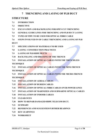
  • 5. Optical Fiber Splicer Trenching and Laying of PLB Duct BRBRAITT, Jabalpur Page 5 of 38 For Restricted Circulation 7.5 TYPES OF PIPE TO BE USED FOR OPTICAL FIBRE CABLE Optical Fibre Cables should be pulled through Permanently Lubricated PLB-HDPE Duct of 40 mm-OD and 33 mm ID Pipe in 200/500/1000 Meter Coil.  Wherever DWC pipe or GI pipes or R.C.C. pipes are used for protection, the two ends of the pipe should be properly sealed to protect HDPE pipe from sharp edge of GI pipe and to bar the entry of rodents. For providing additional protection Split RCC/GI pipes should be used from top instead of full RCC/GI pipes.  Use of normal duty DWC (Double walled corrugated) HDPE pipe – ISI marked and anti-rodent conforming, choosing suitable DWC from nominal OD/ID dia 50/38,63/50,77/63,90/76,120/103,145/126,160/136,175/148 mm).  It is recommended that where ever OFC is passing over the ground surface (exposed outside) and more prone to damage, GI pipe may be used preferably. Depending upon the site conditions and cost consideration one of the protection viz DWC / GI / RCC pipe may be used. 7.6 STEPS INVOLVED IN OF CABLE TRENCHING AND LAYING OF PLB DUCT The Optical Fibre Cable shall be laid through PLB HDPE Ducts buried at a nominal depth of 165cms. All Depths should be measured from the top of pipe. The steps involved in OF Cable trenching are as under:  Excavation of trench up to a nominal depth of 165 cms.in non-Rocky soil, according to construction specifications. Along National/State Highways/other roads and in built up /rural areas. Under exceptional conditions/ genuine circumstances due to site constraints/ soil conditions, relaxation can be granted by the competent authority for excavation of trench to a depth lesser than 165cm. Such relaxation shall be given as per the laid down norms/ procedures being followed by the concerned CPSUs for their own works and with the approval of the competent authority. The payment in such cases shall be made on pro-rata basis as per the existing norms adopted by the
  • 6. Optical Fiber Splicer Trenching and Laying of PLB Duct BRBRAITT, Jabalpur Page 6 of 38 For Restricted Circulation concerned CPSUs. Fig. 1 shows the dimensional view of excavation of trench and other details of installation in normal soil for PLB HDPE pipe. Figure 1: Trench in Normal Soil for PLB HDPE pipe  Laying of PLB HDPE Ducts/coils coupled by sockets in excavated trenches, on bridges and culverts, as per construction specification and sealing of PLB HDPE Ducts pipe ends at every manhole by end-plugs of appropriate size.  Providing additional protection by R.C.C. Pipes/GI pipes and/or concreting/chambering, wherever required. According to construction specification.  Fixing of GI pipes/troughs with clamps on culverts/bridges and/or chambering or concreting of G.I. Pipes/troughs, wherever necessary. Normally, RCC/DWC pipes shall be used and use of GI pipes shall be avoided. However, in case it is felt that GI pipe is unavoidable in certain circumstances this should be done with the prior approval of competent authority within the concerned CPSUs. This shall be recorded appropriately.
  • 7. Optical Fiber Splicer Trenching and Laying of PLB Duct BRBRAITT, Jabalpur Page 7 of 38 For Restricted Circulation  Laying Protection Pipes on Bridges And Culverts. In case trenching and pipe laying is not possible on the culverts, the pipes shall be laid on the surface of the culverts/bridges after due permission from the competent authority as per construction specification  Back filling and Dressing of the Trench according to construction specifications.  Making manhole (of size 2.0 m length x 1.0 m width x 1.65 m Depth) at every Cable pulling location for housing the OF Cable loop & Pulling Optical Fibre Cable using proper tools and accessories. Sealing of both ends of the PLB HDPE pipe in manhole by hard rubber bush of suitable size to avoid entry of rodents into the PLB HDPE Ducts, putting split PLB HDPE Ducts and split RCC pipes with proper fixtures over cable in the manhole to protect the bare cable.  Digging of pit of size 2 meter x 2 meter x 1.8 meter (depth) for fixing of Jointing chambered-cast RCC cover or stone of suitable size on jointing chamber to protect the Joint and backfilling of jointing chamber with excavated soil.  Digging of pits 500 cm to 1000 cm towards jungle side at every manhole and jointing chamber along the route to a depth of 75cms. fixing of route Indicator/joint indicator, concreting and backfilling of pits. Painting of route indicators with Blue colour and joint Indicator by Grey colour and sign writing denoting route/joint indicator number for BBNL. 7.7 SPECIFICATIONS OF MATERIALS TO BE USED 7.7.1 PLB HDPE DUCT Optical Fiber Cables should be pulled though Permanently Lubricated HDPE Duct of 40mm/33 mm. 7.7.1.1 PLB HDPE Duct Accessories a) Push fit Coupler Push Fit couplers shall be used for coupling PLB HDPE ducts/coils.
  • 8. Optical Fiber Splicer Trenching and Laying of PLB Duct BRBRAITT, Jabalpur Page 8 of 38 For Restricted Circulation b) PP Rope The PP rope can be ordered along with the PLB duct as required. In this case PP (Polypropylene Para Pro) ropes drawn through the HDPE/PLB pipes/coils and safely tied to the end caps at either ends with hooks to facilitate pulling of the OF cables at a later stage. c) End Cap End Cap shall be used for sealing the ends of the empty ducts, prior to installation of the OF Cable and shall be fitted immediately after laying the duct to prevent the entry of any dirt, water, moisture, insects/rodents etc. Figure 2: HDPE end Caps d) Cable sealing Plug This shall be used to seal the end of the ducts perfectly, after the OF cable is pulled in the duct. For pulling the cable through the ducts, it is necessary to provide manholes at that location and also at bends and corners wherever required. The ends of the PLB HDPE ducts/coils are closed with Cable sealing Plugs.
  • 9. Optical Fiber Splicer Trenching and Laying of PLB Duct BRBRAITT, Jabalpur Page 9 of 38 For Restricted Circulation 7.7.2 MATERIAL FOR PROVIDING ADDITIONAL PROTECTION 7.7.2.1 RCC Full Round Pipes Reinforced cement concrete pipes (spun type) coupled with RCC collars sealed with cement mortar used to provide additional protection to PLB HDPE Ducts/coils at lessor depths should be of full round, NP-2 class and size 100 cm (internal diameter). The pipes should have a nominal length of 2 meters. The RCC collars should be properly sealed using cement mortar. Figure 3: RCC Collar 7.7.2.2 RCC Split Pipes The split Reinforced cement concrete pipes (spun type) with in-built collars are used to provide additional protection to PLB HDPE Ducts/coils should be of 100mm internal dia. 7.7.2.3 G.I. Pipes G.I. pipes should be of medium duty class having inner diameter of 50 mm.
  • 10. Optical Fiber Splicer Trenching and Laying of PLB Duct BRBRAITT, Jabalpur Page 10 of 38 For Restricted Circulation 7.7.2.4 DWC Pipes Use of normal duty DWC (Double walled corrugated) HDPE as first choice for protection of Optical Fiber Cable instead of GI pipes. The DWC pipes used shall be of size 75/61mm. 7.7.2.5 M.S. Weld Mesh The PLB HDPE Ducts can also be protected by embedding it in concrete of size of 25 cms x25 cms reinforced with MS weld mesh. The strength of RCC/CC is dependent on proper curing, therefore, it is imperative that water content of CC/RCC mix does not drain out into the surrounding soil. Figure 4: M.S. Weld Mesh 7.7.3 JOINT CHAMBER The Joint chamber shall be provided at every joint location to keep the OF cable joint well protected and also to house extra length of cable which may be required in the event of faults at a later date. The Joint chamber shall be of pre-cast RCC type as per construction specification. Brick chamber can also be made with prior permission of Engineer in-charge. 7.7.4 RUBBER BUSH To prevent entry of rodents into PLB HDPE DUCTS, the ends of PLB HDPE DUCTS are sealed at every manhole and joint using rodent resistant hard rubber bush (cap) after optical fibre cable is pulled. The rubber bush should be manufactured from hard rubber with grooves and holes to fit into 40 mm PLB HDPE DUCTS pipe, so that it should be able to prevent the entry of insects, rodents, mud, and rainwater into the PLB HDPE DUCTS pipe.
  • 11. Optical Fiber Splicer Trenching and Laying of PLB Duct BRBRAITT, Jabalpur Page 11 of 38 For Restricted Circulation Figure 5: Rubber Cork 7.7.5 ROUTE/JOINT INDICATOR The Route/Joint indicators are co-located with each manhole/joint chamber. In addition Route indicators are also to be placed where route changes direction like road crossings etc. Either RCC/Pre-cast or Stone based route indicators can be used. 7.8 LAYING / CONSTRUCTION PRACTICES 7.8.1 TRENCHING 7.8.1.1 Location and Alignment of the Trench In built up areas, the trench will normally follow the foot-path of the road except where it may have to come to the edge of the carriage way cutting across road with specific permissions from the concerned authorities maintaining the road (such permissions shall be obtained by the department as per MOU signed with respective State Govt.). Outside the built up limits the trench will normally follow the boundary of the roadside land. However, where the road side land is full of burrow pits or afforestation or when the cable has to cross
  • 12. Optical Fiber Splicer Trenching and Laying of PLB Duct BRBRAITT, Jabalpur Page 12 of 38 For Restricted Circulation culverts/ bridges or streams, the trench may come closer to the road edge or in some cases, over the embankment or shoulder of the Road (permissions for such deviations for cutting the embankment as well as shoulder of the road shall be obtained). Once the alignment is marked, no deviation from the alignment is permissible except with the approval of Engineer-in- charge. While marking the alignment only the center line will be marked and the Contractor shall set out all other work to ensure that, the excavated trench is as straight as possible. The Contractor shall provide all necessary assistance and labor, at his own cost for marking the alignment. Contractor shall remove all bushes, undergrowth, stumps, rocks and other obstacles to facilitate marking the centre line without any extra charges. It is to be ensured that minimum amount of bushes and shrubs shall be removed to clear the way and the contractor shall give all, consideration to the preservation of the trees. The lineup of the trench must be such that PLB pipe(s) shall be laid in a straight line, both laterally as well as vertically except at locations where it has to necessarily take a bend because of change in the alignment or gradient of the trench, subject to the restrictions mentioned elsewhere. 7.8.1.2 Line-Up The line-up of the trench must be such that PLB HDPE Ducts shall be laid in a straight line except at locations where it has to necessarily take a bend because of change in the alignment or gradient of the trench, subject to the restrictions mentioned elsewhere. 7.8.2 METHOD OF EXCAVATION In built up areas, the contractor shall resort to use of manual labour / HDD only to ensure no damage is caused to any underground or surface installations belonging to other public utility services and/or private parties. However, along the Highways and cross country there shall be no objection to the Contractor resorting to mechanical means of excavation, provided that no underground installations existing the path of excavation, if any, are damaged.
  • 13. Optical Fiber Splicer Trenching and Laying of PLB Duct BRBRAITT, Jabalpur Page 13 of 38 For Restricted Circulation There shall be no objection to resort to horizontal boring to bore a hole of required size and to push through G.I. Pipe (50 mm ID) through horizontal bore at road crossing or rail crossing or small hillocks etc. All excavation operations shall include excavation and ‘getting out’. ‘Getting out’ shall include throwing the excavated materials at a distance of at least one meter or half the depth of excavation, whichever is more, clear off the edge of excavation. In all other cases ‘getting out’ shall include depositing the excavated materials as specified. In Rocky strata excavation shall be carried out by use of electro mechanical means like breakers/ jack hammers or by blasting wherever permissible with express permission from the competent authority. If blasting operations are prohibited or not practicable, excavation in hard rock shall be done by chiseling/ jack hammers. Trenching shall as far as possible be kept ahead of the laying of pipes. Contractor shall exercise due care that the soil from trenching intended to be loose for back filling is not mixed with loose debris. While trenching, the Contractor should not cause damage to any underground installations belonging to other agencies and any damage caused should be made good at his own cost and expense. Necessary barricades, night lamps, warning board and required watchman shall be provided by the contractor to prevent any accident to pedestrians or vehicles. While carrying out the blasting operations, the contractor shall ensure adequate safety by cautioning the vehicular and other traffic. The contractor shall employ sufficient man-power for this with caution boards, flags, sign writings etc. The contractor should provide sufficient width at the trench at all such places, where it is likely to cave in due to soil conditions without any extra payment. A minimum free clearance of 15 cms. should be maintained above or below any existing underground installation. No extra payment will be made towards this. In order to prevent damage to PLB HDPE DUCTS over a period of time, due to the growth of trees, roots, bushes, etc., the contractor shall cut them when encountered in the path of alignment of trench without any additional charges.
  • 14. Optical Fiber Splicer Trenching and Laying of PLB Duct BRBRAITT, Jabalpur Page 14 of 38 For Restricted Circulation In large burrow pits, excavation may be required to be carried out for more than 165 cms in-depth to keep gradient of bed less than 15 degrees with horizontal. If not possible as stated above, alignment of trench shall be changed to avoid burrow pit completely. 7.8.3 DEPTH AND SIZE OF THE TRENCH The depth of the trench form top of the surface shall not be less than 165 cms unless otherwise relaxation is granted by competent authority under genuine circumstances. In rocky terrain, less depth shall be allowed only in exceptional circumstances with additional protection where it is not possible to achieve the normal depth due to harsh terrain/ adverse site conditions encountered. This shall be done only with the approval of the competent authority and consent of the Engineer in-charge after following the laid down norms and procedures being followed in the CPSUs concerned. This shall be properly documented. In all cases, the slope of the trench shall not be less than 15 degrees with the horizontal surface. The width of the trench shall normally be 45 cms at the top & 30 cms at the bottom. In case, additional pipes (HDPE/GI/RCC Pipes) are to be laid in some stretches, the same shall be accommodated in this normal size trench. When trenches are excavated in slopes, uneven ground, inclined portion, the lower edge shall be treated, as top surface of land and depth of trench will be measured accordingly. In certain locations, such as uneven ground, hilly areas and all other Places, due to any reason whatsoever it can be ordered to excavate beyond standard depth of 165 cms to keep the bed of the trench as smooth as possible. Near the culverts, both ends of the culverts shall be excavated more than 165 cms. to keep the gradient less than 15 degree with horizontal. For additional depth in excess of 165 cms., no additional payment shall be applicable. If excavation is not possible to the minimum depth of 165 cms. as detailed above, full facts shall be brought to the notice of the Engineer in charge in writing giving details of location and reason for not being able to excavate that particular portion to the minimum depth. Approval shall be granted by the competent authority in writing under genuine circumstances. The decision of the competent authority shall be final and binding on the
  • 15. Optical Fiber Splicer Trenching and Laying of PLB Duct BRBRAITT, Jabalpur Page 15 of 38 For Restricted Circulation contractor. All the relaxations granted as specified above shall be dealt with as per the laid down norms and procedure of CPSUs. 7.8.3.1 Dewatering: The Contractor shall be responsible for all necessary arrangements to remove or pump out water from trench. The Contractor should survey the soil conditions encountered inthe section and make his own assessment about dewatering arrangement that may be necessary. No extra payment shall be admissible for this. 7.8.3.2 Wetting: Wherever the soil is hard due to dry weather conditions, if watering is to be done for wetting the soil to make it loose, the same shall be done by the contractor. No extra payment shall be admissible for this. 7.8.3.3 Blasting: For excavation in hard rock, where blasting operations are considered necessary, the contractor shall obtain approval of the Engineer-in-Charge in writing for resorting to blasting operation. The contractor shall obtain license from the competent authority for undertaking blasting work as well as for obtaining and storing the explosive as per the Explosive Act, 1884 as amended upto date and the explosive Rules, 1983. The contractor shall purchase the explosives fuses, detonators, etc. only from a licensed dealer. Transportation and storage of explosive at site shall conform to the aforesaid Explosive Act and Explosive Rules. The contractor shall be responsible for the safe custody and proper accounting of the explosive materials. Fuses and detonators shall be stored separately and away from the explosives. The Engineer-in-Charge or his authorized representative shall have the right to check the contractor’s store and account of explosives. The contractor shall provide necessary facilities for this. The contractor shall be responsible for any damage arising out of accident to workmen, public or property due to storage, transportation and use of explosive during blasting operation. Blasting operations shall be carried out under the supervision of a responsible authorized agent of the contractor (referred subsequently as agent only), during specified hours as approved in writing by the Engineer-in-Charge. The agent shall be conversant with the rules of blasting. All procedures and safety precautions for the use of
  • 16. Optical Fiber Splicer Trenching and Laying of PLB Duct BRBRAITT, Jabalpur Page 16 of 38 For Restricted Circulation explosives drilling and loading of explosives before and after shot firing and disposal of explosives shall be taken by the contractor as detailed in IS: 4081 safety code for blasting and related drilling operation. 7.8.3.4 Trenching Near Culverts/ Bridges: The PLB HDPE Ducts shall be laid in the bed of culvert at the depth not less than 165 cms protected by RCC pipes as decided by Engineer- in charge. Both ends of culverts shall be excavated more than 165 cms in depth to keep the gradient of not less than 15 degree with horizontal. The bed of trench should be as smooth as possible. While carrying out the work on bridges and culverts, adequate arrangement for cautioning the traffic by way of caution boards during day time and danger lights at night shall be provided. In case of small bridges and culverts, where there is a likelihood of their subsequent expansion and remodeling, the cable should be laid with some curve on both sides of the culvert or the bridge to make some extra length available for readjustment of the cable at the time of reconstruction of culvert or the bridge. 7.9 LAYING OF PLB HDPE DUCTS  After the trench is excavated to the specified depth, the bottom of the trench has to be cleared of all stones or pieces of rock and leveled up properly. A layer of soft soil/or sand (in case the excavated material contains sharp pieces of rock/stones) of not less than 5 cms is required for leveling the trench to ensure that the cable when laid will follow a straight alignment. Adequate care shall be exercised while laying so that the OF cables are not put to undue tension/pressure after being laid as this may adversely affect the optical characteristics of cables with passage of time.  The contractor shall ensure that trenching and pipe laying activities are continuous, without leaving patches or portions incomplete in between. In case intermediate patches are left, measurement of the completed portions will be taken only after work in such left over patches are also completed in all respects.  Preparatory to aligning the pipe for jointing, each length of the PLB HDPE Ducts shall be thoroughly cleaned to remove all sand, dust or any other debris that may clog,
  • 17. Optical Fiber Splicer Trenching and Laying of PLB Duct BRBRAITT, Jabalpur Page 17 of 38 For Restricted Circulation disturb or damage the optical fibre cable when it is pulled at a later stage. The ends of each pipe and inside of each Socket shall be thoroughly cleaned of any dirt or other foreign materials.  After the trench is cleaned the PLB HDPE Ducts/Coil shall be laid in the cleaned trench, jointed with Sockets. Drawing up of PP rope is optional as per TEC GR. In case of use of PP Rope, at every manhole approximately at every 200m or at bends or turns the PP rope will be tied to the HDPE end caps used for sealing the PLB HDPE Ducts, to avoid entry of rodents/mud etc.  At the end of each day work, the open ends of the pipes sections shall be tightly closed with endcaps to prevent the entry of dirt/mud, water or any foreign matter into PLB HDPE Ducts until the work is resumed. In built up area falling within Municipal/Corporation limits, the PLB HDPE Ducts shall be laid with protection using RCC Pipes/ Concreting reinforced with weld mesh (only in exceptional cases).  For lesser depths requiring additional protection in built up areas, towns and cities falling within t the municipal limits, suitable protection shall be provided to PLB HDPE pipes/coils using RCC/DWC full round/split pipes or GI pipes or cement concreting reinforced with MS weld mesh or a combination of any of these as per the site requirement. This shall be done only with the prior instructions/approval of the Engineer-in-charge. The specifications for providing each of these protections are given later in this document.  Moreover, in cross country routes, if depth is less than 1.2 meters, protection by using RCC/DWC Pipe shall be provided. Engineer-in-Charges shall decide about such stretches and type of protection to be provided in view of the site requirements. Normally 100 mm RCC /DWC Pipes shall be used for protecting PLB HDPE Ducts but if more than one PLB pipe is to be laid and protected, RCC/DWC Pipe of suitable size to accommodate the required number of PLB Pipes shall be used.  The PLB HDPE Ducts shall be laid in RCC Full Round spun Pipes/GI Pipes as required at Road crossings. The RCC pipes/GI pipes shall extend at least 3 meters on either side of the road at Road crossings. At Road crossings, extra GI/PLB HDPE Ducts may be laid as per the direction of the Engineer-in charge. On Rail bridges and
  • 18. Optical Fiber Splicer Trenching and Laying of PLB Duct BRBRAITT, Jabalpur Page 18 of 38 For Restricted Circulation crossings, the PLB HDPE Ducts shall be encased in suitable cast iron as prescribed by the Railway Authorities.  Wherever RCC pipes are used for protection, the gaps between the RCC collars and the RCC pipe shall be sealed.  Wherever GI pipes are used, special care should be taken to ensure that G.I. Pipes are coupled properly with the sockets so as to avoid damage to PLB pipe and eventually the OF Cable in the event of pressure coming on the joint and G.I. Pipe joint giving its way. Rubber bushes shall be used at either ends of the GI pipes to protect PLB pipe.  In case of protection by concreting at site, the nominal dimension of concreting shall be 250 mm x250 mm section.  For carrying out concreting work in trenches, yellow PVC sheets of width not less than 1.0 M shall be spread and nailed on sides of the trench to form trapezoidal section for concreting in the cleaned trench, to avoid seepage of water into the soil.  A bed of cement concrete mixture of appropriate width and 75 mm thickness shall be laid on the PVC sheet, before laying PLB HDPE ducts. The PLB HDPE Ducts shall then be laid above this bed of concrete. After laying the PLB HDPE Ducts, MS weld mesh is wrapped around and tied and concrete mix is poured to form the cross sectional dimensions as instructed by the Engineer-in-charge.  The strength of RCC is dependent on proper curing therefore, it is imperative that water content of RCC mix does not drain out into the surrounding soil. Portions where cement concreting has been carried out shall be cured with sufficient amount of water for reasonable time to harden the surface. After curing, refilling of the balance depth of the trench has to be carried out with excavated soil.  The PLB HDPE Ducts/RCC/GI Pipes shall be laid only in trenches accepted by Engineer-in-Charge or his representative. The Contractor shall exercise due care to ensure that the PLB HDPE Ducts are not subjected to any damage or strain.
  • 19. Optical Fiber Splicer Trenching and Laying of PLB Duct BRBRAITT, Jabalpur Page 19 of 38 For Restricted Circulation  Water present in the trench at the time of laying the PLB HDPE Ducts shall be pumped out by the contractor before laying the pipes in the trench to ensure that no mud or water gets into the pipes, thus choking it.  In case of nallahs, which are dry for nine months in a year, the PLB HDPE Ducts shall be laid inside the RCC Pipes laid at a minimum depth of 165 cms., as instructed by the Engineer-in-charge. The mechanical protection shall extend at least 5 meters beyond the bed of nallah on either side.  Notwithstanding anything contained in clauses referred above, the Engineer-in-charge may order, based on special site requirements, that the PLB HDPE Ducts may be encased in reinforced cement concrete. While laying the pipes, a gap of 2 M is kept at convenient locations approx. 200 m apart and at the bends and turns, which will be used as manholes during OF cable pulling. Ends of the PLB HDPE Ducts at the manholes shall be sealed using end caps after tying the PP rope to the end caps to avoid choking of the pipes. In a similar manner, manholes shall be kept while approaching bridges, road crossings etc., as instructed by the Engineer-in-charge. The location of the manholes will be decided by the Engineer-in-charge. 7.9.1 LAYING PROTECTION PIPES ON BRIDGES AND CULVERTS: In case trenching and pipe laying is not possible on the culverts, the pipes shall be laid on the surface of the culverts/bridges after due permission from the competent authority. Of late the bridge construction authorities are providing channel ducts on the footpaths on the bridges for various services. The RCC/DWC/ G.I. Pipes can be laid in these ducts for pulling cables. However, for laying cables on existing bridges, where duct arrangement does not exist, one of the following methods may be adopted. a. In case of the Bridges/Culverts, where there are no ducts and where the cushion on the top of the Arch is 50 cm to 100 cm or more, G.I. Pipe (Carrying PLB HDPE pipe and cable) may be buried on the top of the Arch adjoining the parapet wall, by digging close to the wheel guards. Every precaution shall be taken to see that no damage occurs to the arch of the culvert. After burying the GI pipe, the excavated surface on the arch shall be restored.
  • 20. Optical Fiber Splicer Trenching and Laying of PLB Duct BRBRAITT, Jabalpur Page 20 of 38 For Restricted Circulation b. Where the thickness of the Arch is less than 50 cms, the pipe must be buried under the wheel guard masonry and the wheel guard rebuilt. c. If neither of the two methods is possible, the G.I. Pipes/GI Troughs must be clamped on the parapet wall with the clamps. If necessary, the pipes may be taken through the parapet wall at the ends where the wall diverges away from the road. Methods cited in above clauses should be carried out under close supervision of Road authorities. The surface to be concreted should be thoroughly cleaned and leveled before concreting. At both ends of the Bridges/Culverts, where the GI Pipes /GI Troughs slope down and get buried, the concreting should be extended sufficiently to ensure that no portion of the GI Pipes/GI Troughs is exposed as approved by the Engineer- in- charge to protect the pipe/trough from any possible externally caused damage. Where white wash/colour wash is existing on the Bridges/ Culverts, the same should also be carried out on the concreted portion to ensure uniformity. 7.10 BACK FILLING AND DRESSING OF THE TRENCH Provided that the PLB HDPE pipes have been properly laid in the trench at the specified depth, the back filling operation shall follow as early as practicable. The earth used for filling shall be free from all roots, Grass, shrubs, vegetation, trees, saplings and any other kind of garbage or pebbles. The back filling operation shall be performed in such a manner so as to provide firm support under and above the pipes and to avoid bend or deformation of the PLB HDPE pipes when the pipes get loaded with the back filled earth. At locations where the back filled materials contains stones/sharp objects which may cause injury to the PLB HDPE pipes and where the excavated or rock fragments are intended to refill the trench in whole or in part, the trench should be initially filled, with a layer of ordinary soil or loose earth (free from any stones/pebbles) not less than 10 cms thick over the pipes.
  • 21. Optical Fiber Splicer Trenching and Laying of PLB Duct BRBRAITT, Jabalpur Page 21 of 38 For Restricted Circulation Back filling on public, roads, railway crossings, footpaths in city areas shall be performed immediately after laying the HDPE pipes. Back filling at such locations shall be thoroughly rammed, so as to ensure original condition so that it is safe for the road traffic. All excess soil/ material left on road/ footpath/railway crossing shall be removed by contractor. However, along the highways and in country side, the excess dug up material left over after refilling should be kept in a heap above over the trench. In city limits, at any given time not more than 50 Meters length of trench should be kept open and in all places where excavation has been done, no part of the trench should be kept open over night to avoid occurrence of any mishap or accident in darkness. 7.11 INSTALLATION OF OPTICAL CABLES WITH THE TRENCHLESS TECHNIQUE Horizontal directional drilling is an excellent alternative to traditional utility installation methods. Unlike manual labor, trenching or excavation, the HDD process is highly suitable in urban areas or places where aboveground obstructions exist that are expensive, inconvenient or impossible to disturb for product installation. HDD machines install utilities under obstacles such as roads, rivers, creeks, buildings and highways — with little or no impact to the aboveground surface. The trenchless techniques (or no-dig techniques) allow installation of underground optical cables minimizing or eliminating the need for excavation. These techniques create a horizontal bore below the ground in which the underground infrastructure (ducts, pipes or direct buried cables) can be placed. Trenchless techniques can reduce environmental damage and social costs and, at the same time, provide an economic alternative to open-trench methods of installation.
  • 22. Optical Fiber Splicer Trenching and Laying of PLB Duct BRBRAITT, Jabalpur Page 22 of 38 For Restricted Circulation Figure 6: General scheme of the directional drilling technique: drilling the pilot hole From a general point of view, the trenchless techniques are very useful in the following situations:  where road surface excavation is restricted or prohibited by administrative agencies, etc. (newly constructed roads, emergency vehicle entrances/exits, etc.);  where the open-cut method cannot assure safety or would cause risks to traffic and pedestrians;  where noise, vibration, dust and other pollution are caused by open-cut method;  where the open-cut method may impede road traffic and thus hinder the business of nearby stores;  where congested sections where open-cut method may damage the buried facilities of other companies or sections where the presence of buried objects causes significant lack of work efficiency;  where conduits should be buried at deep locations and open-cut construction would greatly increase the amount of excavated soil;  where road surfaces use high-grade material which would increase the cost of reinstatement after excavation;
  • 23. Optical Fiber Splicer Trenching and Laying of PLB Duct BRBRAITT, Jabalpur Page 23 of 38 For Restricted Circulation  where road sections with high traffic volumes limit the work to the night-time hours (lower work efficiency, higher labour costs);  where open-cut construction would involve extra costs to move historic remains or other items.  normally 250cms depth is possible  bore dia 100mm for 4 PLB or less pipes and for 5-8 PLB Bore dia 200mm.  depth at the entry should be 165cms.  depth, deviation and offset to be provided by machine automatically with graph.  HDD is normally deployed in soft soil.  GI route indicators at every 200 meter manhole and 30 cm above ground level The choice of the most suitable technique to be adopted is related to each type of application, as outlined in the following.  Long installation lengths can be achieved (several km) by dividing the work length into shorter sections (100-200 m as an average). The length of each section will depend on the characteristics of the machines and the design requirements. Boring/directional drilling (both fluid-assisted and dry boring) machines should be used for this particular application.  River and railway crossings were the first applications of trenchless technology due to the fact that traditional digging techniques were not suitable. Surface-launched machines are often the best solution because obstacles can be crossed with a curved drilling path, thus avoiding the need to excavate deep launch and reception pits (especially in river crossings). It is possible to consider two different kinds of crossing with respect to the length and to the depth of the installed duct: i) Road and railway crossings: For both, the length of the drilling is normally not very long, so that both fluid-assisted and dry directional drilling machines can be used, or the use of micro-tunnelling systems depending on the duct diameter;
  • 24. Optical Fiber Splicer Trenching and Laying of PLB Duct BRBRAITT, Jabalpur Page 24 of 38 For Restricted Circulation ii) River crossings: The length and the depth of the bore normally required are very long and deep, and it is important to avoid the excavation of big launch and reception pits on the opposite sides of the river. For these situations the drilling is started directly from the surface using a fluid assisted directional drilling system.  Urban environments are also very attractive for the application of trenchless technology because it could avoid, or drastically reduce, the troublesome drawbacks normally created by digging work in urban areas. Due to the small diameters of the ducts and the short distance of each drilling section (manholes or chambers are normally very close together), a small and dry directional rig is used, in order to reduce the overall dimension of the working site, and to avoid flooding of the drilling fluid along the drilling path and the use of micro-tunnelling systems, depending on the duct diameter. 7.12 INSTALLATION OF OPTICAL CABLES WITH THE MINI- TRENCH TECHNIQUE The so-called mini-trenching technique allows the installation (in small trenches) of underground optical cables in ducts. The advantages of this technique over conventional cable laying technologies lie essentially in its speed of execution, lower cost, significantly lower environmental impact and limited disruption to road traffic and, as a consequence of the previous items, easiness in obtaining permits for the taking over of public area. The mini-trenching technique can be applied on routes that generally involve asphalted surfaces such as roads and sidewalks with a compact soil subgrade. It is not recommended that the technique be used on routes where the soil subgrade is sandy, gravelly or contains medium-sized cobbles (i.e., measuring 10 to 20 cm in diameter). If other underground utilities crossing a planned route already exist at a depth interfering with the depth of the mini-trench, this technology is not appropriate. 7.12.1.1 Traditional mini-trench (10 × 30 cm) Mini-trenching is normally carried out by simultaneously cutting through the paving and digging a trench whose depth and cross-section vary in accordance with the number of ducts to be laid: depth is normally between 30 and 40 cm, while cross-section can vary
  • 25. Optical Fiber Splicer Trenching and Laying of PLB Duct BRBRAITT, Jabalpur Page 25 of 38 For Restricted Circulation between 7 and 15 cm. In order to guarantee a protection against impact resulting from road- repairing, the depth of the laid infrastructure shall be maintained constant at a known level that must be 5 cm deeper than the foreseen asphalt cutting depth normally specified for road surface repair works. Figure 7: Example of mini-trenching installation configuration In cases where the mini-trench is dug along a road with no curb or sidewalk, the excavation shall normally be located at distance of around one metre from the edge of the road (or, if possible, just on the external side of the lateral line). In special circumstances where this is not possible, the mini-trench may be dug in the shoulder at the edge of the asphalt. Any crossings through unpaved sections (which must in any case have a compact subgrade) should be carried out using the same technique. 7.12.2 THE ENHANCED MINI-TRENCH Further mini-trench technique development has resulted in a new solution in which all phases of duct/cable laying are simultaneous. In details, the enhanced mini-trench is characterized by reduced dimensions of 5 cm wide and 30 cm deep (mini-trench 5 × 30), In the enhanced mini-trench 5 × 30 it is possible to lay one Ø 50 mm duct or two (one laid upon the other).
  • 26. Optical Fiber Splicer Trenching and Laying of PLB Duct BRBRAITT, Jabalpur Page 26 of 38 For Restricted Circulation Figure 8: Example of mini-trench 5 × 30 cm configuration The enhanced mini-trench allows one to operate with smaller machinery on narrow roads, producing a lower quantity of waste material and thereby reducing operating expense. So, this solution can operate both in urban and in non-urban environments. Figure 9: Example of application of enhanced mini-trench 5 × 30 cm technology
  • 27. Optical Fiber Splicer Trenching and Laying of PLB Duct BRBRAITT, Jabalpur Page 27 of 38 For Restricted Circulation 7.13 INSTALLATION OF OPTICAL CABLES WITH THE MICRO- TRENCH TECHNIQUE The micro-trenching technology can be applied on routes that involve asphalted surfaces, such as roads or sidewalks with a base of compact material (asphalt or concrete). Its advantages over conventional cable-laying technologies lie essentially in its speed of execution, major reduction in infrastructure deployment costs, and significantly lower impact on the environment and on road traffic. Protection against breakage from road reparation is not possible due to the shallow depths used in micro-trenching techniques. It is therefore essential to carefully plan the routes on which these techniques are to be used, in order to provide long-term stability of the routes. Micro-trenching is normally carried out by cutting a shallow groove in the asphalt (better if not less than 7 cm), but without penetrating past the asphalt layer. Care must be taken to avoid cutting entirely through the asphalt, as this could cause the pavement along the sides of the groove to crack or split. This precaution must be borne in mind in all cases where there is no lateral protection on one or both sides of the groove, which can prevent the asphalt layer from shifting, and particularly in cases where micro-trenching is performed along the edge of a road with no curb or sidewalk. In such cases, the groove shall normally be located at a suitable distance (e.g. at least one metre) from the edge of the road. Groove width may vary (e.g. 10-15 mm) in accordance with the diameter of the cable laid. The optical fibres are preferably enclosed in a metallic (e.g. copper) tube filled with a suitable filling compound and surrounded by a polyethylene jacket.
  • 28. Optical Fiber Splicer Trenching and Laying of PLB Duct BRBRAITT, Jabalpur Page 28 of 38 For Restricted Circulation Figure 10: Sharp change in route direction 7.14 INSTALLATION OF AERIAL CABLES Optical aerial cable include the normal practices for both self-supporting cables (all dielectric or including a metallic element) and lashed cables (e.g. attached to a pre-installed tension strand). The mechanical stresses and, therefore, strain experienced during aerial cabling are generally less than those induced during underground placing and in a mixed underground/overhead route underground cable may, with care, be used for overhead sections. In general, where end-pull or distributed pull methods are used, the various types of systems indicated in the above clauses to protect the cable from excessive strain during installation may be employed for aerial cable and it is good practice also to ensure that cable back-tension is always carefully controlled. Where lashing to pre-tensioned support wire or existing metallic cable is employed, the optical fibre aerial cable must be constructed to withstand lashing. The lashing-wire tension must also be carefully controlled. Great care must be exercised when handling cable in aerial route installations. Provided the need to protect from overload and over-bending is borne in mind, most normal aerial cable installation winching equipment including end-pull winches, intermediate winches, controlled cable feeding devices, etc., can be used. For long length installations, where end-pull or distributed-pull systems are used, it is very important that proper guiding
  • 29. Optical Fiber Splicer Trenching and Laying of PLB Duct BRBRAITT, Jabalpur Page 29 of 38 For Restricted Circulation equipment is provided at positions where sharp changes of direction occur, and every effort should be made to ensure pulling-in at an even speed. Figure 11: Aerial cable pulling through system 7.15 INSTALLATION OF BURIED CABLES Normal buried cable installation methods, including ploughing (direct, vibratory or winched), trenching and moling, can, in general, be used for direct burial of optical fibre cable, provided the cable is specifically designed for this type of application. The same depth of cover as for metallic cables is usually adequate, but traffic capacity or other considerations of security may indicate a requirement for greater depth. Where a trench method is used, back filling materials and practices may require particular consideration so that fibre strain limits are not reached during this operation. Figure 12: Installation by cable ploughing
  • 30. Optical Fiber Splicer Trenching and Laying of PLB Duct BRBRAITT, Jabalpur Page 30 of 38 For Restricted Circulation When ploughing methods are used the design of the guiding equipment between the cable reel and the cable laying guide must take careful account of specified cable bending criteria and have a low friction value to prevent fibre overstrain. Cable overload protection systems are not normally necessary but, where a large ploughing machine is used and there are driven cable reels and guide wheels, a tension device can be incorporated. In-service mechanical protection at road or service crossings or in situations of high vulnerability may be felt to be necessary. 7.16 INSTALLATION OF OPTICAL FIBRE CABLES OVER POWER LINES Optical fibres are particularly suitable for use on the aerial power lines in high-voltage networks, because they are immune by electromagnetic influences. Optical Fibre Cables for laying over Power Lines: These cables are installed on the overhead power distribution network. Following are the few types of the Optical Fibre Cable for laying over Power Line. 1. All-Dielectric Self-supporting (ADSS) Optical Fibre Cable for laying on power line alignments - To be installed on the overhead power distribution network up to 33 KV. 2. Optical Ground Wire (OPGW) Cable for laying on power lines) - To be installed on existing high voltage Power Line alignments beyond 33 KV, up to 400 KV. The cable may also replace the existing Ground Wire of the alignment. 7.17 INSTALLATION OF MARINIZED AND SUBMARINE OPTICAL CABLES Underwater optical fibre cables are classified (according to the ITU-T Recommendations), in the three following categories:  marinized terrestrial cable;  repeater-less submarine cable;
  • 31. Optical Fiber Splicer Trenching and Laying of PLB Duct BRBRAITT, Jabalpur Page 31 of 38 For Restricted Circulation  repeatered submarine cable. Marinized terrestrial cables are generally used for crossing lakes and rivers. Repeater- less submarine cable is suitable for use in both shallow and deep waters for lengths up about 300 km. Repeatered submarine cables can be used in all underwater applications, mainly for deep waters on lengths that require the deployment of submerged repeaters. Prior to any marinized /submarine system implementation a survey normally is conducted in order to find the optimum route and to give the cable the optimum protection along this route. Usually a submarine cable is manufactured in cable plants close to the beach in order to facilitate the loading aboard of a vessel. For marinized cables to be installed in rivers or lakes, with the cable to be delivered by terrestrial transportation, the loading method adopted is the same as that for terrestrial cables. For the repeatered submarine cable systems, after the loading, the single elementary factory lengths are jointed to the submerged repeaters and to all the other submerged equipment in order to form on the cable ship the link to be laid without stopping the ship. Figure 13: Laying of repeatered submarine cables 7.18 INSTALLATION OF INDOOR CABLES Within buildings various types of optical fibre cable construction can be used and it is important to ensure that the most appropriate type for each part of the indoor network is
  • 32. Optical Fiber Splicer Trenching and Laying of PLB Duct BRBRAITT, Jabalpur Page 32 of 38 For Restricted Circulation employed. It may be that the bending criteria of the incoming cable is more stringent than internal types and it may be advantageous, where possible, to site line terminating equipment near the building cable entry or a cable riser. Where cables are routed along the floor, a short straight route is preferable with cable passing through, rather than around, walls to avoid sharp bends. For under floor installation, computer type flooring is normally satisfactory. Non-ruggedized cable is best run in conduit, racks or trays, but care must be taken to ensure that turning points are properly constructed so that cable bending criteria can be satisfied. Where cable is fitted directly to walls, care must be taken to ensure proper cleats and straps are used and that they are not over tightened. Much internal optical fibre cable installation is done by hand; therefore, the possibility of fibre overstrains during this handling should be borne in mind. 7.19 CLEARANCES The Contractor shall be responsible for obtaining necessary clearances for excavation work from the authorities on behalf of the Employer and provide requisite copies of information, maps, survey report etc to the authorities. The Employer shall assist the Contractor in obtaining such clearances by providing the authority letter or any other relevant document. 7.20 HOW TO REPAIR DAMAGED HDPE TELECOM DUCT. The HDPE Telecom duct system can be damaged during the construction activities of other utilities or agricultural activities, if the duct route is not traced properly, or when executing agencies do not respect the importance of tracing the duct route. Often people who dig the trenches or construct the main duct, route damage existing communications networks, because they have not properly identified the location of the underground network, before digging. Duct can be damaged either when empty or white housing optic fibre cable. The methods to repair these two possible situations are quite different. 7.20.1 HOW TO REPAIR EMPTY DUCT: The location of the damage should be excavated for three meters along the troubled area. The manhole must be big enough, including width, for labours to work comfortably.
  • 33. Optical Fiber Splicer Trenching and Laying of PLB Duct BRBRAITT, Jabalpur Page 33 of 38 For Restricted Circulation  Cut off the damaged part of the duct.  Prepare the same length, same size, and same colour of spare length.  Debar the ends of both ducts entering the manhole and the two ends of the new piece. Connect the joints with plastic Couplers.  Place locator or markers on the newly placed Couplers and enter this data into any relevant documentation.  Place the Coupler into the ground and cover with fine sand or soil. Place warning tape and cover with earth when finished. 7.21 SUMMARY Optical fibre must be protected from excessive strains, produced axially or in bending, during installation and various methods are available to do this. The aim of all optical fibre cable installation methods and systems should be to install the cable with the fibre in, as near as possible, a strain free condition, ready for splicing. Methods and practices used in the handling of optical fibre cables during installation can, without producing any immediately evident physical damage or transmission loss, affect their long term transmission characteristics. After placement of PLB HDPE duct, the duct must be capped or plugged to prevent moisture or foreign matter from entering until the cable installation starts. 7.22 REFERENCES AND SUGGESTED FURTHER READINGS  ITU-T manual on OF installation  EI of BSNL  EI on underground OF cable laying works by BBNL  Fiber Optics Technician's Manual  Understanding optical communication by Dutton  Planning Fiber Optic Networks by Bob Chomycz  www.timbercon.com
  • 34. Optical Fiber Splicer Trenching and Laying of PLB Duct BRBRAITT, Jabalpur Page 34 of 38 For Restricted Circulation  http://www.ofsoptics.com  http://www.thefoa.org/  http://www.corning.com  http://www.fiber-optics.info  http://www.rp-photonics.com  http://www.occfiber.com and other websites 7.23 KEY LEARNINGS Qu. 1: Fill in the blanks a) The width of the trench shall normally be …………. cms at the top & ………cms at the bottom. b) Standard depth of trench should be …………….cms. c) Approval shall be granted by the ……………………….. for depth relaxation. d) if depth is less than 1.2 meters, protection by using …………… Pipe shall be provided. e) Back filling and dressing of the trench is commonly called……………………………… Qu. 2: State True or False a) Trenchless technique is used where road surface excavation is allowed by administrative agencies. b) HDD is normally deployed in rocky soil. c) Traditional mini-trench dimensions are 10 × 30 cm. d) Optical fibers are particularly suitable for use on the aerial power lines in high-voltage networks, because they are immune by electromagnetic influences.
  • 35. Optical Fiber Splicer Trenching and Laying of PLB Duct BRBRAITT, Jabalpur Page 35 of 38 For Restricted Circulation e) The Contractor shall be responsible for obtaining necessary clearances for excavation work from the authorities on behalf of the Employer and provide requisite copies of information, maps, survey report etc to the authorities. Qu. 3: Write down methods of excavation? ---------------------------------------------------------------------------------------------------------------- ---------------------------------------------------------------------------------------------------------------- ---------------------------------------------------------------------------------------------------------------- ---------------------------------------------------------------------------------------------------------------- ---------------------------------------------------------------------------------------------------------------- ---------------------------------------------------------------------------------------------------------------- ---------------------------------------------------------------------------------------------------------- Qu. 4: In which situation the HDD is preferred? ---------------------------------------------------------------------------------------------------------------- ---------------------------------------------------------------------------------------------------------------- ---------------------------------------------------------------------------------------------------------------- ---------------------------------------------------------------------------------------------------------------- ---------------------------------------------------------------------------------------------------------------- ---------------------------------------------------------------------------------------------------------------- ---------------------------------------------------------------------------------------------------------------- ---------------------------------------------------------------------------------------------------------- 7.24 WORKSHEET 1. Identify and write down the use of PLB HDPE Duct Accessories? Sl. No. Name of accessories Use 1 Push fit Coupler 2 PP Rope 3 End Cap 4 Cable sealing Plug
  • 36. Optical Fiber Splicer Trenching and Laying of PLB Duct BRBRAITT, Jabalpur Page 36 of 38 For Restricted Circulation 2. Write down the steps to repair the empty PLB duct? ---------------------------------------------------------------------------------------------------------------- ---------------------------------------------------------------------------------------------------------------- ---------------------------------------------------------------------------------------------------------------- ---------------------------------------------------------------------------------------------------------------- ---------------------------------------------------------------------------------------------------------------- ---------------------------------------------------------------------------------------------------------------- ---------------------------------------------------------------------------------------------------------------- ---------------------------------------------------------------------------------------------------------- 3. Write down the different methods/technique used for the installation of Optical fiber cable and their application areas? Sl. No. Installation Technique Application 4. Write down the dimension of different trenches? Name of Trenches Dimension Open cut Trench Mini Trench Micro Trench Notes: ---------------------------------------------------------------------------------------------------------------- ---------------------------------------------------------------------------------------------------------------- ---------------------------------------------------------------------------------------------------------------- ---------------------------------------------------------------------------------------------------------------- ----------------------------------------------------------------------------------------------------------------
  • 37. Optical Fiber Splicer Trenching and Laying of PLB Duct BRBRAITT, Jabalpur Page 37 of 38 For Restricted Circulation ---------------------------------------------------------------------------------------------------------------- ---------------------------------------------------------------------------------------------------------------- ---------------------------------------------------------------------------------------------------------------- ---------------------------------------------------------------------------------------------------------------- ---------------------------------------------------------------------------------------------------------------- ---------------------------------------------------------------------------------------------------------------- ---------------------------------------------------------------------------------------------------------------- ---------------------------------------------------------------------------------------------------------------- ---------------------------------------------------------------------------------------------------------------- ---------------------------------------------------------------------------------------------------------------- ---------------------------------------------------------------------------------------------------------------- ---------------------------------------------------------------------------------------------------------------- ---------------------------------------------------------------------------------------------------------------- ---------------------------------------------------------------------------------------------------------------- ---------------------------------------------------------------------------------------------------------------- ---------------------------------------------------------------------------------------------------------------- ---------------------------------------------------------------------------------------------------------------- ---------------------------------------------------------------------------------------------------------------- ---------------------------------------------------------------------------------------------------------------- ---------------------------------------------------------------------------------------------------------------- ---------------------------------------------------------------------------------------------------------------- ---------------------------------------------------------------------------------------------------------------- ---------------------------------------------------------------------------------------------------------------- ---------------------------------------------------------------------------------------------------------------- ---------------------------------------------------------------------------------------------------------------- ---------------------------------------------------------------------------------------------------------------- ---------------------------------------------------------------------------------------------------------------- ---------------------------------------------------------------------------------------------------------------- ---------------------------------------------------------------------------------------------------------------- ---------------------------------------------------------------------------------------------------------------- ---------------------------------------------------------------------------------------------------------------- ---------------------------------------------------------------------------------------------------------------- ----------------------------------------------------------------------------------------------------------------
  • 38. Optical Fiber Splicer Trenching and Laying of PLB Duct BRBRAITT, Jabalpur Page 38 of 38 For Restricted Circulation ---------------------------------------------------------------------------------------------------------------- ---------------------------------------------------------------------------------------------------------------- ---------------------------------------------------------------------------------------------------------------- ---------------------------------------------------------------------------------------------------------------- ---------------------------------------------------------------------------------------------------------------- ---------------------------------------------------------------------------------------------------------------- ---------------------------------------------------------------------------------------------------------------- ---------------------------------------------------------------------------------------------------------------- ---------------------------------------------------------------------------------------------------------------- ---------------------------------------------------------------------------------------------------------------- ---------------------------------------------------------------------------------------------------------------- ---------------------------------------------------------------------------------------------------------------- ---------------------------------------------------------------------------------------------------------------- ---------------------------------------------------------------------------------------------------------------- ---------------------------------------------------------------------------------------------------------------- ---------------------------------------------------------------------------------------------------------------- ---------------------------------------------------------------------------------------------------------------- ---------------------------------------------------------------------------------------------------------------- ----------------------------------------------------------------------------------------------------------