Abengoa Innovation - Hydrogen service station Infrastructure
•
1 recomendación•867 vistas

Abengoa is working to produce renewable energy based hydrogen for commercial use either from reforming natural gas or electrolysis.

Recomendados
Recomendados
Más contenido relacionado
La actualidad más candente
La actualidad más candente (20)
Destacado
Destacado (20)
Similar a Abengoa Innovation - Hydrogen service station Infrastructure
Similar a Abengoa Innovation - Hydrogen service station Infrastructure (20)
Más de Abengoa
Más de Abengoa (20)
Último
Último (20)
Abengoa Innovation - Hydrogen service station Infrastructure
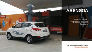
- 1. Business Development 1 Dr. Juan Fernández García 01/03/2017 Infrastructure: Hydrogen Service Stations
- 2. 321 Index 54 Compression, Storage and Dispensing Systems Outline of dispensing systems Abengoa Innovation Organization and strategic approach Abengoa’s Projects Project references for hydrogen service stations Hydrogen Supply Infrastructure General outline of the plant On-site Hydrogen Production Systems Electrolysis and reforming systems 2
- 4. Abengoa Innovation 4 Hydrogen Production: Procyon Project 300 kWe cogeneration plant, with electric and thermal production, based on a molten carbonate fuel cell (MCFC), from natural gas as the only fuel. Electronic Power Systems: Aress Project Design, execution and operation of a 1 MW energy storage system, capable of softening the production curve of a photovoltaic plant or regulating both the frequency and the supply voltage. Aerospace Main activities center around the electric and electronicproducts for aerospace and defense sectors, as well as enhancing synergies between space-based and energy technologies. 1H
- 6. Diagram of a hydrogen supply plant with on-site production Hydrogen supply infrastructure 6
- 8. Diagram of reforming production systemsOn-site Production 8 MTS1 MTS2 HX HX Burner HX HX HX HX HX Water Flue gas PSA / Membrane exhaust gas Fuel Fuel Oxygen Reformer Pure hydrogen gas (>99% H2 vol) 1 2 3 4 PSA system 10- 40 bar Membrane separation system
- 9. Diagram of production systems using electrolysisOn-site Production 9 Electrolysis stage H2O Water treatment Power adaptation system Electricity Separation stage H2+ H2OO2+ H2O H2 O2 Purification stage Recycled H2O Thermal control system Heat H2 (to final application) Tap water Electricity from the power grid
- 11. Diagram of compression, storage and dispensing systems Compression, Storage and Dispensing 11 Time-Fill Configuration H2Storage (LowPressure) HydrogenProduction Hydrogen Production and buffer storage Dispenser (350baror700bar) Compression and dispensing
- 12. Diagram of compression, storage and dispensing systems Compression, Storage and Dispensing 12 Buffer Fast Fill Configuration H2Storage (LowPressure) HydrogenProduction Hydrogen production and buffer storage Dispenser (350baror700bar) High Pressure Storage Precooing Compression, storage, precooling and dispensing
- 13. Diagram of compression, storage and dispensing systems Compression, Storage and Dispensing 13 Cascade Fast Fill Configuration H2Storage (LowPressure) HydrogenProduction Hydrogen production and buffer storage Dispenser (350baror700bar) High Pressure Storage Medium Pressure Storage Low Pressure Storage Precooing Compression, storage, precooling and dispensing
- 14. 5 Projects 14
- 15. Las Columnas Service station in Sanlúcar la Mayor, Seville, Spain. Service station producing hydrogen on-site by using water electrolysis in an alkaline electrolyzer from photovoltaic solar power. Production capacity up to 25 kg/day. Supply: 350 bar. Project start date: 2005. Project end date: 2009. Co-financed by: Andalusian Regional Government (IDEA Agency). CTA. Science and Innovation Ministry. ERDF Funds. Las Columnas: Sanlúcar La Mayor service stationProyectos 15
- 16. ESH2 2.0 Service station in Torrecuéllar, Seville, Spain. Service station producing hydrogen by using water electrolysis in a PEM electrolyzer from electricity from the grid. Production capacity up to 65 kg/day. Supply: 350 bar. Project start date: 2013. Project end date: 2015. Co-financed by: Andalusian Regional Government (IDEA Agency). ESH2 2.0: Torrecuéllar service stationProjects 16
- 17. Newbusfuel: EMT service station (municipal transport company)Projects 17 Newbusfuel Design for a service station at the EMT facilities in Madrid, Spain. Supplying a fleet of 100 buses. Service station produces hydrogen by using water electrolysis in a PEM electrolyzer from electricity from the grid and also by means of reforming with steam from natura l gas. Production capacity: up to 3000 kg/day. Storage capacity: more than 5000 kg/day. Supply: 350 bar. Project start date: 2015. Project end date: 2017. Co-financed by: FCH-JU.
- 18. Co-financersProjects 18 Co-financing: The following organizations have co-financed the projects:
- 19. Thank you. 19