Isolite Cleaning & Maintenance
•
1 recomendación•22,098 vistas

How to clean and maintain your Isolite Illuminated Dental Isolation System.

Recomendados
Más contenido relacionado
La actualidad más candente
La actualidad más candente (20)
Destacado
Destacado (19)
Similar a Isolite Cleaning & Maintenance
Similar a Isolite Cleaning & Maintenance (20)
Último
Último (20)
Isolite Cleaning & Maintenance
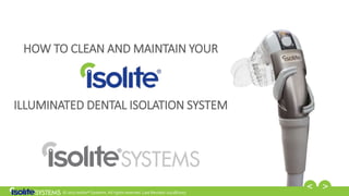
- 1. © 2017 Isolite® Systems. All rights reserved. Last Revised: 02/28/2017 HOW TO CLEAN AND MAINTAIN YOUR ILLUMINATED DENTAL ISOLATION SYSTEM
- 2. © 2017 Isolite® Systems. All rights reserved. Last Revised: 02/28/2017 2 Step One: Disassembly
- 3. © 2017 Isolite® Systems. All rights reserved. Last Revised: 02/28/2017 3 After Each Patient, Remove the Mouthpiece from the Control Head and Safely Dispose of It. Re-use of the mouthpiece can result in the transmission of infectious pathogens SINGLE-USE MEANS SAFE. Mouthpieces are single-use only to eliminate the risk of patient cross contamination.
- 4. © 2017 Isolite® Systems. All rights reserved. Last Revised: 02/28/2017 4 Remove the Vacuum Light Pipe from the Control Head Press and hold the rectangular release button on the underside of the Control Head to release and disconnect the Vacuum Light Pipe.
- 5. © 2017 Isolite® Systems. All rights reserved. Last Revised: 02/28/2017 5 Remove the LED Smart Stick Remove the LED Smart Stick from the Titanium Control Base by gently pulling it out in an arcing motion.
- 6. © 2017 Isolite® Systems. All rights reserved. Last Revised: 02/28/2017 6 Remove the Control Head from the Power Hose Carefully remove the Control Head by grasping the end of the Power Hose and pulling it straight off. DO NOT TWIST
- 7. © 2017 Isolite® Systems. All rights reserved. Last Revised: 02/28/2017 7 Cap the End of the Power Hose with the Suction Line Plug Suction Line Plug
- 8. © 2017 Isolite® Systems. All rights reserved. Last Revised: 02/28/2017 8 Remove the Vacuum Levers from the Titanium Control Base Remove the Vacuum Levers by rotating the levers to the off position. Keep pushing gently until each lever pops out. Titanium Control Base Vacuum Levers
- 9. © 2017 Isolite® Systems. All rights reserved. Last Revised: 02/28/2017 9 Your System Is Now Properly Disassembled Vacuum Light Pipe LED Smart Stick Titanium Control Base Vacuum Levers
- 10. © 2017 Isolite® Systems. All rights reserved. Last Revised: 02/28/2017 10 Step Two: Surface Disinfection Between Each Patient
- 11. © 2017 Isolite® Systems. All rights reserved. Last Revised: 02/28/2017 11 Between Each Patient, Perform a Surface Disinfection of the LED Smart Stick DO NOT SUBMERSE, AUTOCLAVE, CHEMCLAVE, OR PLACE IN ULSTRASONIC CLEANER Follow the cleaning recommendations provided in the Instructions for Use Wipe down the surface of the LED Smart Stick with an intermediate level disinfectant wipe with a claim to inactivate Mycobacterium tuberculosis.
- 12. © 2017 Isolite® Systems. All rights reserved. Last Revised: 02/28/2017 12 Between Each Patient, Perform a Surface Disinfection of the Titanium Control Base Wipe down the surface of the Titanium Control Base with an intermediate level disinfectant wipe with a claim to inactivate Mycobacterium tuberculosis. Titanium Control Base Vacuum Levers
- 13. © 2017 Isolite® Systems. All rights reserved. Last Revised: 02/28/2017 13 Between each patient, perform a surface disinfection of the Power Hose Wipe down the surface of the Power Hose with an intermediate level disinfectant wipe with a claim to inactivate Mycobacterium tuberculosis.
- 14. © 2017 Isolite® Systems. All rights reserved. Last Revised: 02/28/2017 14 Step Three: Cleaning
- 15. © 2017 Isolite® Systems. All rights reserved. Last Revised: 02/28/2017 15 Six Vacuum Light Pipes Are Provided So One Is Always Ready When You Need It
- 16. © 2017 Isolite® Systems. All rights reserved. Last Revised: 02/28/2017 16 Clean the Vacuum Light Pipe Using the provided Double End Tube Brush and a neutral pH (6.5-7.5) enzymatic cleaning solution, remove biomatter and debris from the suction channels. After cleaning, rinse with tap water and dry. DO NOT HOLD PARTS IN CLEANING SOLUTION.
- 17. © 2017 Isolite® Systems. All rights reserved. Last Revised: 02/28/2017 17 Clean the Titanium Control Base Using the provided Double End Tube Brush and a neutral pH (6.5-7.5) enzymatic cleaning solution, remove biomatter and debris from the suction channels. After cleaning, rinse with tap water and dry. DO NOT HOLD PARTS IN CLEANING SOLUTION OR USE ULTRASONIC CLEANERS
- 18. © 2017 Isolite® Systems. All rights reserved. Last Revised: 02/28/2017 18 According to Frequency of Use, Regularly Clean the inside of the Power Hose to Prevent Accumulation of Biofilm PRIOR TO CLEANING, UNPLUG THE POWER ADAPTER FROM THE POWER HOSE Start by vacuuming water through the Power Hose. Then, vacuum a dental hose cleaner with a pH between 6 and 8, through the Power Hose per manufacturer’s instructions.
- 19. © 2017 Isolite® Systems. All rights reserved. Last Revised: 02/28/2017 19 Step Three: Sterilization
- 20. © 2017 Isolite® Systems. All rights reserved. Last Revised: 02/28/2017 20 Follow the sterilization recommendations provided in the Instructions for Use Before Use on a Patient, Sterilize the Vacuum Light Pipes
- 21. © 2017 Isolite® Systems. All rights reserved. Last Revised: 02/28/2017 21 Before Use on a Patient, Sterilize the Vacuum Light Pipes Place the Vacuum Light Pipes into an autoclave pouch and sterilize in a steam autoclave using these validated sterilization cycles. Cycle Temperature Min. Exposure Time Min. Drying Time Standard 121 °C / 250 °F 30 min 30 min Standard 132 °C / 270 °F 15 min 15 min Prevacuum 132 °C / 270 °F 4 min 20 min Prevacuum 134 °C / 273 °F 3 min 20 min
- 22. © 2017 Isolite® Systems. All rights reserved. Last Revised: 02/28/2017 22 Follow the sterilization recommendations provided in the Instructions for Use Weekly, or as Needed per Standard Office Protocol, Sterilize the Titanium Control Base Titanium Control Base Vacuum Levers
- 23. © 2017 Isolite® Systems. All rights reserved. Last Revised: 02/28/2017 23 Weekly, or as Needed per Standard Office Protocol, Sterilize the Titanium Control Base Place the Titanium Control Base and Vacuum Levers into an autoclave pouch and sterilize in a steam autoclave using these validated sterilization cycles. Cycle Temperature Min. Exposure Time Min. Drying Time Standard 121 °C / 250 °F 30 min 30 min Standard 132 °C / 270 °F 15 min 15 min Prevacuum 132 °C / 270 °F 4 min 20 min Prevacuum 134 °C / 273 °F 3 min 20 min
- 24. © 2017 Isolite® Systems. All rights reserved. Last Revised: 02/28/2017 24 Step Four: Lubrication and Reassembly
- 25. © 2017 Isolite® Systems. All rights reserved. Last Revised: 02/28/2017 25 Inspect the Vacuum Lever O-rings for Damage If the O-rings shows signs of cracking, breakage, or crusty build-up that can not be completely cleaned with a wet cotton swab, the O-ring will need to be removed and replaced. If properly maintained and lubricated, the O-ring can last for many months or years.
- 26. © 2017 Isolite® Systems. All rights reserved. Last Revised: 02/28/2017 26 If Necessary, Remove the O-ring from the Vacuum Levers Using a probe with a point, pinch and slide the O-ring to one side to create a small loop. Slide the O-ring off. Insert the probe point under the O-ring.
- 27. © 2017 Isolite® Systems. All rights reserved. Last Revised: 02/28/2017 27 Replace the O-ring on the Vacuum Levers Roll the O-ring onto the end of the Vacuum Lever valve barrel and into the groove. O-ring in place.
- 28. © 2017 Isolite® Systems. All rights reserved. Last Revised: 02/28/2017 28 Lubricate the Vacuum Lever O-rings Coat the O-ring by applying a small amount of the Dow 111 O-ring Lubricant provided in the O-ring Maintenance Kit. THE VACUUM LEVER O-RINGS REQUIRE REGULAR LUBRICATION TO OPERATE AT PEAK EFFICIENCY.
- 29. © 2017 Isolite® Systems. All rights reserved. Last Revised: 02/28/2017 29 Inspect the Power Hose O-ring for Damage If the O-ring shows signs of cracking, breakage, or crusty build-up that can not be completely cleaned with a wet cotton swab, the O-ring will need to be removed and replaced. The O-ring is located less than ½ inch inside the blue plastic fitting at the head of the Power Hose.
- 30. © 2017 Isolite® Systems. All rights reserved. Last Revised: 02/28/2017 30 If Necessary, Remove the O-ring from the Power Hose Hold the head of the Power Hose and insert a probe with a point under the O-ring. Gently guide the probe around the groove. The O-ring should come out. Pull out the O-ring.
- 31. © 2017 Isolite® Systems. All rights reserved. Last Revised: 02/28/2017 31 Replace the O-ring on the Power Hose Pinch the O-ring and insert one end into the groove. Using the probe, massage the O-ring into the groove.
- 32. © 2017 Isolite® Systems. All rights reserved. Last Revised: 02/28/2017 32 Lubricate the Power Hose O-ring Coat the O-ring by applying a small amount of the Dow 111 O-ring Lubricant provided in the O-ring Maintenance Kit. THE POWER HOSE O-RING REQUIRES REGULAR LUBRICATION TO OPERATE AT PEAK EFFICIENCY
- 33. © 2017 Isolite® Systems. All rights reserved. Last Revised: 02/28/2017 33 Reconnect the Control Head to the Power Hose and Reinsert the LED Smart Stick
- 34. © 2017 Isolite® Systems. All rights reserved. Last Revised: 02/28/2017 34 Reattach the Vacuum Light Pipe to the Control Head
- 35. © 2017 Isolite® Systems. All rights reserved. Last Revised: 02/28/2017 35 THANK YOU. PLEASE CONTACT US IF YOU HAVE ANY QUESTIONS OR NEED ANY ADDITIONAL SUPPORT.