
Recomendados
Recomendados
Más contenido relacionado
La actualidad más candente
La actualidad más candente (18)
Similar a Network Monitoring with Wireshark
Similar a Network Monitoring with Wireshark (20)
Último
Último (20)
Network Monitoring with Wireshark
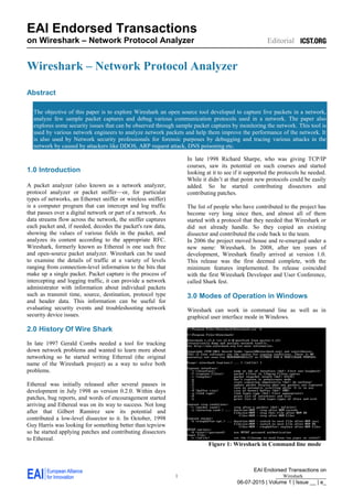
- 1. EAI Endorsed Transactions on _________________ 06-07-2015 | Volume 1 | Issue __ | e_ EAI Endorsed Transactions on Wireshark – Network Protocol Analyzer Editorial 1 Wireshark Wireshark – Network Protocol Analyzer Abstract The objective of this paper is to explore Wireshark an open source tool developed to capture live packets in a network, analyze few sample packet captures and debug various communication protocols used in a network. The paper also explores some security issues that can be observed through sample packet captures by monitoring the network. This tool is used by various network engineers to analyze network packets and help them improve the performance of the network. It is also used by Network security professionals for forensic purposes by debugging and tracing various attacks in the network by caused by attackers like DDOS, ARP request attack, DNS poisoning etc. 1.0 Introduction A packet analyzer (also known as a network analyzer, protocol analyzer or packet sniffer—or, for particular types of networks, an Ethernet sniffer or wireless sniffer) is a computer program that can intercept and log traffic that passes over a digital network or part of a network. As data streams flow across the network, the sniffer captures each packet and, if needed, decodes the packet's raw data, showing the values of various fields in the packet, and analyzes its content according to the appropriate RFC. Wireshark, formerly known as Ethereal is one such free and open-source packet analyzer. Wireshark can be used to examine the details of traffic at a variety of levels ranging from connection-level information to the bits that make up a single packet. Packet capture is the process of intercepting and logging traffic, it can provide a network administrator with information about individual packets such as transmit time, source, destination, protocol type and header data. This information can be useful for evaluating security events and troubleshooting network security device issues. 2.0 History Of Wire Shark In late 1997 Gerald Combs needed a tool for tracking down network problems and wanted to learn more about networking so he started writing Ethereal (the original name of the Wireshark project) as a way to solve both problems. Ethereal was initially released after several pauses in development in July 1998 as version 0.2.0. Within days patches, bug reports, and words of encouragement started arriving and Ethereal was on its way to success. Not long after that Gilbert Ramirez saw its potential and contributed a low-level dissector to it. In October, 1998 Guy Harris was looking for something better than tcpview so he started applying patches and contributing dissectors to Ethereal. In late 1998 Richard Sharpe, who was giving TCP/IP courses, saw its potential on such courses and started looking at it to see if it supported the protocols he needed. While it didn’t at that point new protocols could be easily added. So he started contributing dissectors and contributing patches. The list of people who have contributed to the project has become very long since then, and almost all of them started with a protocol that they needed that Wireshark or did not already handle. So they copied an existing dissector and contributed the code back to the team. In 2006 the project moved house and re-emerged under a new name: Wireshark. In 2008, after ten years of development, Wireshark finally arrived at version 1.0. This release was the first deemed complete, with the minimum features implemented. Its release coincided with the first Wireshark Developer and User Conference, called Shark fest. 3.0 Modes of Operation in Windows Wireshark can work in command line as well as in graphical user interface mode in Windows. Figure 1: Wireshark in Command line mode
- 2. Siddharth Coontoor 2 The Wireshark in command line mode supports a large number of command line parameters. The command line parameters can be explored using the command "wireshark -h" in the command line. All the functions that the tool supports in the graphical user interface can be also executed using the command line. Figure 1 is a screen shot of subset of the command line parameters. In the graphical interface mode, the Wireshark tool makes capturing and monitoring the packets very easy using a different colour scheme for different communication protocol. This feature makes it convenient for the security professionals to identify the various protocol messages and filter them using filtering rules or patterns so that they can remove the unwanted packets and focus only on the packets they are interested in from the packet capture. Figure 2: Graphical interface of Wireshark Figure 2 shows a sample screenshot of Wireshark graphical interface. Wireshark will typically display information in three panels. The top panel lists frames individually with key data on a single line. Any single frame selected in the top pane is further explained in the tool's middle panel. In this section of the display, Wireshark shows packet details, illustrating how various aspects of the frame can be understood as belonging to the data link layer, network layer, transport layer or application layer. Finally, Wireshark's bottom pane displays the raw frame, with a hexadecimal rendition on the left and the corresponding ASCII values on the right. It is easy to observe that the green coloured packets are TCP and packets marked in blue are DNS etc. 4.0 Analyzing Packets in a capture Wireshark is not an intrusion detection system. It will not warn the user when someone does strange things on the network that he/she is not allowed to do. However, if strange things happen, Wireshark would help to figure out what is really going on. Wireshark will not manipulate things on the network, it will only "measure" things from it. Wireshark does not send packets on the network or do other active operations. It would first do a packet capture by capturing all the packets in the network. This activity is sometimes called as sniffing and an attacker could also do this for reconnaissance. Network engineers would perform packet captures to monitor the network and debug the network for performance issues whereas Security professionals would use these captures to identify and debug malwares and other threats to the network. To perform a packet capture of the network in Windows operating system, the user would have to download the WinPcap driver (called NPF) which is also provided by Wireshark. This requires administrator privileges. Once the driver is loaded, every local user can capture from it until it's stopped again. While capturing packet from a network the NIC card would have to be enabled in promiscuous mode. This is a mode for a wired network interface controller (NIC) or wireless network interface controller (WNIC) that causes the controller to pass all traffic it receives to the central processing unit (CPU) rather than passing only the frames that the controller is intended to receive. The NIC would start to capture all the packets in the network in formats like .cap, .libcap, .pcap etc. The act of capturing packets in a network without the consent of the owner of the network could be considered malicious and the user could face legal actions, therefore it is best to perform these actions by consulting a lawyer. As seen in Figure 2, we observe in the second panel of the tool that different packets are represented by different colours. This is a feature in the tool that makes it easy for the user to identify the protocols when viewing a packet capture. The colour codes for every protocol is completely customizable. Figure 3 illustrates the customizable screen and the currently assigned colour rules set for the packets. Figure 3: Colouring Rules for packets Another useful feature in the tool is the filter. The filter allows the user to search for particular strings in packets and also create labels using pattern expressions and saving them for later use. This helps security and network
- 3. Wireshark – Network Protocol Analyzer 3 professionals to zero down on what they are looking for in thousands on packets that they are looking at. 5.0 Network Monitoring and Identifying Threats Using Wireshark This section introduces scenarios that demonstrates how Wireshark can be used to effectively to monitor network and understand the protocols using Scenarios 1 and 2. Also explores how the tool can be used by security professionals to investigate and analyze network threats like detecting port scanning, ARP cache poisoning and malware downloaded through websites. These techniques are used widely for forensic purposes and used to understand, document and publish the threats to the security community and help design a solution to avoid further exploits. 5.1 Scenario 1: Http packet request and response capture and analysis Wireshark supports capture and analysis of HTTP packets and allows the administrator to view the process of connection establishment in detail. This section explores how to analyze a simple HTTP connection using a packet capture. A detailed HTTP connection process flow diagram and TCP handshake process can be referenced while tracing the packets for clarity as presented in the Appendix A.1. In this scenario, the packet capture shows a client representing IP 145.254.160.237 establishing a connection with server 65.208.228.223. Snapshot 1 Initially, there is a TCP handshake between the client and server. This can be seen by looking at the frames 1, 2, 3 (snapshot 1) and observing the ACK and SYN flags. Also observe that the sequence and acknowledgment numbers that indicates that the connection is as per the flow diagram in Appendix A.1. Snapshot 2 As soon as the initial TCP handshake is established, we can say that the client has successfully connected to the server. Next, the client sends a HTTP GET request seen in frame 4 (snapshot 2). Also observe in the TCP level, the ports communicating between the client and the server are 3372 and 80(HTTP) respectively as shown in the snapshot 3. Snapshot 3 In the same packet at the HTTP level we can see exactly what the client is requesting from the server in the HTTP format. We see the client sending details to the server about the User Agent , the formats it would accept and languages it supports etc. as shown in the below snapshot 4. In addition Wireshark also mentions the response to this request is present at frame 38 making it easy to follow the communication in the last line. Snapshot 4 The frame 38 is a packet sent from the server to the client which contains the HTTP response and the page requested in by the client. The details can be seen in the HTTP response header in the frame 38 in the snapshot 5 below. Snapshot 5 Lastly, once the HTTP request/response phase is completed, the client and server would want to end the connection in a graceful manner, this can be seen in the below snapshot 6 where the client and server send FIN flag enabled TCP packets to close the connection gracefully.
- 4. Siddharth Coontoor 4 Snapshot 6 5.2 Scenario 2: SSL Handshake and encrypted payload capture and analysis SSL (Secure Sockets Layer) is the standard security technology for establishing an encrypted link between a web server and a browser. This section explores a packet capture of an SSL handshake between a server and a browser and also views the encrypted payload and methods that Wireshark provides to decrypted the payload using the encryption key. This can be used by security professionals for forensic analysis to gather information and evidence of communications between two parties. In this packet capture, the client and server are different ports of the same machine 127.0.0.1 communicating through ports 38713 and 443(default port for SSL). The SSL handshake protocol can be referenced from the Appendix A.2. This packet capture includes a SSL handshake in which a RSA key exchange algorithm is being used. Initially, a TCP three way handshake takes place that establishes connection between the client and the server as shown in snapshot 7. Snapshot 7 Once connection established, the client would send a “CLIENT HELLO” to the server which contains SSL protocol version, Session ID, a list of cipher suits client supports which the server would need to securely communicate with the client. This is seen in snapshot 8. Snapshot 8 Now the server would send a “SERVER HELLO” encapsulating information that a client would need to securely communicate with the server. This is seen in frame 6 as shown in the snapshot 9. Snapshot 9 The “SERVER HELLO” contains SSL version, session specific data, cipher selected for secure communication and the server’s certificate that contains the public key. The above cipher suite has been selected by the server which indicates that SSL version 3 TLS is used for secure communication, RSA is used for key exchange and 256 bit AES in CBC mode would be used for symmetric encryption and SHA algorithm for integrity of the messages exchanged. The client would now first validate the validate the server’s certificate and use the public key specified in the certificate to encrypt a pre master secret and sends it to the server. The pre master secret is created by the client based on the cipher suite selected by the server. This client key exchange is seen in frame 8 in the screenshot 10. Snapshot 10 Now, the server uses its private key to decrypt the pre master secret and generate the master key with the agreed cipher. Using this master secret they generate the
- 5. Wireshark – Network Protocol Analyzer 5 symmetric session key which would be used from now to encrypt and decrypt messages exchanged between them. The client and server therefore use asymmetric keys to establish a symmetric key that will be used throughout the session. The encrypted payload can be seen sent from the client to server in snapshot 11. Snapshot 11 Additionally, Wireshark also provides the functionality of decrypting the encrypted payload provided one has the session key. The below snapshot 12 shows the method of decrypting the payload by inserting the key into the packet capture. Snapshot 12 Snapshot 12, shows that after providing details of the IP address and port of the server, the underlying protocol used and the session key used to encrypt the application payload, the tool would decrypt the payload and allow the security professionals to gain information about the messages exchanged. Snapshot 13 Snapshot 13 shows packet capture after the decryption of the communication marked in green by the tool. 5.3 Scenario 3: NMAP OS Fingerprinting Scan OS fingerprinting is the process of determining the operating system used by a host on a network. This technique can be used by attackers to understand and gain more information about the systems in the target network. If an attacker can identify the operating systems that run on specific target machine, they can then learn which exact vulnerabilities to exploit. Each and every OS in deployment has unique bugs and vulnerabilities. When an exact OS is determined, it is really easy to research what they are. That is even often true when bug reports have not been sent to vendors already, and the corresponding patches have yet to be developed. So, hardening against OS fingerprinting can, in some cases, prevent zero-day attacks. Nmap ("Network Mapper") is a free and open source utility for network discovery and security auditing. Many systems and network administrators also find it useful for tasks such as network inventory, managing service upgrade schedules, and monitoring host or service uptime. This tool is often used by attackers in OS fingerprinting systems of the target network. It is therefore important to detect and harden against OS fingerprinting. This section demonstrates a packet capture of an active NMAP OS fingerprinting scan. Active fingerprinting works by sending packets to a target and analyzing the packets that are sent back. In this capture we observe the various packets sent by an attacker to the network. When Nmap scan is executed on a remote machine, it sends a number of TCP, UDP, and ICMP probes to the target machine. Nmap sent probes to lots of different TCP/IP ports, and analyzes what returned. Specific OSes and network service applications leave different types of data in their TCP, UDP, and ICMP packets. Nmap utilizes scripting that analyzes that data to print out results that are useful for OS fingerprinting. In the following packet capture, a host at IP 172.1.16.150 is a target of a NMAP OS fingerprint scan by IP 172.16.16.128 (attacker). The packet capture reveals a variety of packets sent by 172.16.16.128 that include TCP, UDP and ICMP echo. The packet capture includes frames in which the attacker tries to send these packets to port 135 and make the target host reply to these requests.
- 6. Siddharth Coontoor 6 Snapshot 14 The snapshot 14 shows 26 frames with respect to the relative times and several different types of packets have been sent by IP 172.16.16.128 to the host at IP 172.1.16.150 and port 135. Frames 1-12 show IP 172.16.16.128 create half open connections using TCP SYN/ACK and gathering the responses from the host machine. Also, the attacker at IP 172.16.16.128 uses different ports (53936-53941 and 53948-53952) to initiate the half open TCP connections, so as to bypass any firewall restrictions. In frame 13-16 we see ICMP ping requests from the attacker and the subsequent replies from the host. Frame 17,26 shows a UDP packet sent from attacker to the host to check if port 42283 is open, since the host doesn’t reply with a ICMP destination unreachable error code it is most likely that the UDP port is open. Frames 18-25 show TCP requests and responses to attacker with various flags like URG, CWR, ECN, FIN that seem to indicate a OS fingerprinting scan from IP 172.16.16.128. 5.4 Scenario 4: ARP cache poisoning at packet level Address Resolution Protocol (ARP) is a protocol for mapping an Internet Protocol address (IP address) to a physical machine address that is recognized in the local network. The physical machine address is also known as a Media Access Control (MAC). A table, usually called the ARP cache, is used to maintain a correlation between each MAC address and its corresponding IP address. Every machine in a local network maintains its own copy of the ARP cache. ARP provides the protocol rules for making this correlation and providing address conversion in both directions. When an incoming packet destined for a host machine on a particular local area network arrives at a gateway, the gateway asks the ARP program to find a physical host or MAC address that matches the IP address. The ARP program looks in the ARP cache and, if it finds the address, provides it so that the packet can be converted to the right packet length and format and sent to the machine. If no entry is found for the IP address, ARP broadcasts a request packet in a special format to all the machines on the LAN to see if one machine knows that it has that IP address associated with it. A machine that recognizes the IP address as its own returns a reply so indicating. ARP updates the ARP cache for future reference and then sends the packet to the MAC address that replied. This section explores ARP Poisoning that takes advantage of the overly trusting ARP system. By sending forged ARP packets, an attacker can cause a victim to send traffic to any nodes on the local network or perform a man-in-the-middle attack or also potentially cause a denial of service by broadcasting a bogus MAC address for the default gateway. There are two primary types of ARP messages: 1. ARP Request: This is a message broadcasted to IP addresses essentially asking "who has this IP address?" 2. ARP Reply: The machine with the IP address responds to the request with its MAC address. All machines that hear the reply cache the MAC address. Snapshot 15 In this packet capture as seen in snapshot 15, filtering to only "arp" packets and observing frame 54 which appears to be an arp request asking "who has 172.16.0.107? Tell 172.16.0.1". This packet sent by the attacker manages to poison the ARP cache of machine with IP address 172.16.0.107. The injected packet at frame 54 exploits the ARP protocol since ARP assumes that when a machine receives an ARP Request, it trusts the MAC/IP pair of the requester and thus the machine updates its ARP Table with the senders MAC and IP pair. Here the MAC (00:25:b3:bf:91:ee) as seen in the specially crafted packet in the is of the attacker and the IP address(172.16.0.1) is spoofed. The subsequent ARP responses in frame 55, 56 would be treated as unsolicit replies and ignored.
- 7. Wireshark – Network Protocol Analyzer 7 Snapshot 16 Furthermore as seen in snapshot 16, frame 165 shows a broadcast ARP request packet that is sent to all machines in the local network asking "who has 172.16.0.1? Tell 172.16.0.105". The result the attacker manages to poison all cache table entries to IP 172.16.0.105 with his MAC address (00:25:b3:bf:91:ee). 5.5 Scenario 5: Distributed Denial Of service By TCP SYN Flood attack TCP SYN flood is a type of Distributed Denial of Service (DDoS) attack that exploits part of the normal TCP three- way handshake to consume resources on the targeted server and render it unresponsive. Essentially, with SYN flood DDoS, the offender sends TCP connection requests faster than the targeted machine can process them, causing network saturation. A normal TCP three way handshake can be seen in Appendix A.1. In a SYN flood attack, the attacker sends repeated SYN packets to every port on the targeted server, often using a fake IP address. The server, unaware of the attack, receives multiple, apparently legitimate requests to establish communication. It responds to each attempt with a SYN-ACK packet from each open port. The malicious client either does not send the expected ACK, or if the IP address is spoofed never receives the SYN-ACK. Either way, the server under attack will wait for acknowledgement of its SYN-ACK packet for some time. During this time, the server cannot close down the connection by sending an RST packet, and the connection stays open. Before the connection can time out, another SYN packet will arrive. This leaves an increasingly large number of connections half open. Eventually, as the server’s connection overflow tables fill, service to legitimate clients will be denied, and the server may even malfunction or crash causing a denial of service to legitimate clients. Snapshot 17 Snapshot 17 shows a packet capture which demonstrates a host at IP 192.168.0.1 being flooded with SYN TCP packets from various IPs. These machines IP addresses could be either spoofed IPs or could be botnets that the attacker controllers to launch this attack. The tool clearly captures these random clients sending SYN packets to the host to create the half open connections and attempts to create a denial of service for legitimate clients.
- 8. Siddharth Coontoor 8 Appendix A. Protocols and Flow Diagrams This section provides protocols and its flow diagrams for reference purposes as used in the scenarios. A.1. HTTP connection and TCP handshake flow diagram: HTTP connection between client and server flow diagram TCP Handshake Flow diagram A.2. SSL Handshake: References [1] https://en.wikipedia.org/wiki/Packet_analyzer [2] https://en.wikipedia.org/wiki/Wireshark [3] http://searchsecurity.techtarget.in/definition/Wireshark [4] https://www.wireshark.org/docs/wsug_html_chunked/ChIn troHistory.html [5] http://malware-traffic-analysis.net/index.html [6] http://www.netresec.com/?page=PcapFiles [7] https://www.wireshark.org/docs/man-pages/ [8] https://en.wikipedia.org/wiki/Pcap [9] https://en.wikipedia.org/wiki/Promiscuous_mode [10] http://www.symantec.com/connect/blogs/trojanhydraq- incident-analysis-aurora-0-day-exploit [11] https://www.wireshark.org/docs/wsug_html_chunked/ChC ustColorizationSection.html [12] http://www.symantec.com/connect/blogs/how-does-ssl- work-what-ssl-handshake [13] http://resources.infosecinstitute.com/must-know-os- fingerprinting/ [14] http://forensicswiki.org/wiki/OS_fingerprinting [15] http://chrissanders.org/packet-captures/ [16] http://www.arppoisoning.com/demonstrating-an-arp- poisoning-attack/ [17] http://searchnetworking.techtarget.com/definition/Address- Resolution-Protocol-ARP [18] http://searchsecurity.techtarget.com/definition/SYN- flooding