Ijeee 33-36-surveillance system for coal mines based on wireless sensor network

Abstract: The foremost critical task for coal mine is of keeping track of miners spread out across a large mining areas .It becomes even difficult when mine tunnels collapse. Many mines use a radio system to track miners, but when a collapse occurs, the base stations connected by a thin wire often are rendered useless. In this project to overcome the demerits of radio system we used wireless technology for tracking the miners. For this purpose a small RF transmitter module is equipped to each person entering a mine. Each transceiver placed in the mine look after the location of miners. The transceivers communicate with base stations through Zigbee module. In addition of tracking the location of miners we also include sensors such as temperature & humidity to intimate the base station & miners when some atmosphere changes occur. Mine operators are now able to monitor the real-time locations of each miner to better pinpoint their locations in the event of an emergency. Even after a full-day of use, mine operators can locate an individual miner within ten feet. Key Words: Wireless sensor networks (WSN), ZIGBEE, and LPC2148.

Recomendados
Recomendados
Más contenido relacionado
La actualidad más candente
La actualidad más candente (20)
Similar a Ijeee 33-36-surveillance system for coal mines based on wireless sensor network
Similar a Ijeee 33-36-surveillance system for coal mines based on wireless sensor network (20)
Más de Kumar Goud
Más de Kumar Goud (20)
Último
Último (20)
Ijeee 33-36-surveillance system for coal mines based on wireless sensor network
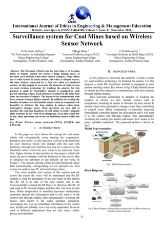
- 1. International Journal of Ethics in Engineering & Management Education Website: www.ijeee.in (ISSN: 2348-4748, Volume 1, Issue 11, November 2014) 33 Surveillance system for Coal Mines based on Wireless Sensor Network G.Venkata Aditya 1 P.Bujji Babu 2 U.Yedukondalu 3 1 M.Tech student in Embedded Systems 2 Assistant Professor, Dept of ECE 3 Associate Professor & HOD, Dept of ECE Aditya Engineering College Aditya Engineering College Aditya Engineering College Surampalem, Andhra Pradesh, India Surampalem, Andhra Pradesh, India Surampalem, Andhra Pradesh, India Abstract: The foremost critical task for coal mine is of keeping track of miners spread out across a large mining areas .It becomes even difficult when mine tunnels collapse. Many mines use a radio system to track miners, but when a collapse occurs, the base stations connected by a thin wire often are rendered useless. In this project to overcome the demerits of radio system we used wireless technology for tracking the miners. For this purpose a small RF transmitter module is equipped to each person entering a mine. Each transceiver placed in the mine look after the location of miners. The transceivers communicate with base stations through Zigbee module. In addition of tracking the location of miners we also include sensors such as temperature & humidity to intimate the base station & miners when some atmosphere changes occur. Mine operators are now able to monitor the real-time locations of each miner to better pinpoint their locations in the event of an emergency. Even after a full-day of use, mine operators can locate an individual miner within ten feet. Key Words: Wireless sensor networks (WSN), ZIGBEE, and LPC2148. I. INTRODUCTION In this paper we have shown the concept for coal mines which will automatically sense sensing the temperature, humidity and smoke. A user interface is given in the hardware for user interface which will interact with the user with hardware, through user interface user can set a value or set the threshold values which the user wants to be informed about that. Zigbee Section is that interface in this project, which will make the user to interact with the hardware so that user is able to initialize the hardware or can initially set the value. In Figure 1, The sensors sensing values exceeds threshold values then automatically corresponding device operated and then values are send to user PC and monitoring values. The voice module also include in this section and the across the action the voice will be announced and the RF module is used for attendance in the coal mine in this section the RF ID is at user of the coal miners and at the Microcontroller connect the RF Receiver. Receives the RF ID and send to PC through Zigbee and that data will store in data base. When temperature or humidity increases immediately controller detects the information and it will send it to the control unit through Zigbee, then automatically switching the motor, here motor is for water sprinkler indication. Advantages are, it gives immediate information to the control unit, Simple and reliable, Low cost, easily applicable. It can be used in different applications they are coal mines, public places and industries. II. PROPOSED WORK In this project to overcome the demerits of radio system we used wireless technology for tracking the miners. For this purpose a small RF transmitter module is equipped to each person entering a mine. It is shown in fig.3. Easy identification to miners and the transceivers communicate with base stations through Zigbee module. Take real-time scheduling in addition of tracking the location of miners we also include sensors such as temperature, humidity & smoke to intimate the base station & miners when some atmosphere changes occur then controlling to control room. When temperature or humidity increases immediately controller detects the information and it will send it to the control unit through Zigbee, then automatically switching the cooling fan, buzzer and motor, here motor is for water sprinkler indication. The proposed system is shown in fig.2. Model Representation: Fig1: Model Representation. Block Diagram: Fig:2 Block Diagram of Surveillance system for Cole Mines based on Wireless Sensor Network.
- 2. International Journal of Website: www.ijeee.in (ISSN: 2348 Miners: Fig3: Mine Section. Server Section: Fig4: Monitoring Section. 2.1 Zigbee Module Interfacing with LPC2148 The microcontroller output is not compatible with the Zigbee module. To make it compatible we require the DB9 connector and the MAX 232 connector. This will enable the microcontroller to send a message to a predefined is performed. 2.2 LCD Interface with LPC2148: The system also consists of a display system having in corresponding response display information on LCD module has 8-bit data interface and control pins as shown in Figure 3. One can send data as 8-bit or in pair of nibbles. To display any character on LCD micro controller has to send its ASCII value to the data bus of LCD. For e.g. to display 'AB' microcontroller has to send two hex bytes 41h and 42h respectively. Fig5. LCD interfacing with microcontroller Ethics in Engineering & Management Education Website: www.ijeee.in (ISSN: 2348-4748, Volume 1, Issue 11, November 34 with LPC2148: The microcontroller output is not compatible with the module. To make it compatible we require the DB9 connector and the MAX 232 connector. This will enable the microcontroller to send a message to a predefined when action The system also consists of a display system having response display information on LCD. LCD bit data interface and control pins as shown in bit or in pair of two 4-bit nibbles. To display any character on LCD micro controller has to send its ASCII value to the data bus of LCD. For e.g. to display 'AB' microcontroller has to send two hex bytes 41h microcontroller LCD display used here is having 16x2 each with 16 characters. 2.3 Embedded Processor: In the proposed work, from ARM-7 family. It is manufactured by Philips and it is pre-loaded with many inbuilt peripherals making it more efficient and a reliable option for the beginners as well as high end application developer. The features of LPC214x series controllers chip static RAM and 32 to 512 memory.128 bit wide interface/accelerator enables high speed 60 MHz operation. In-System/In (ISP/IAP) via on-chip boot- sector or full chip erase in 400 ms and programming of 256 bytes in 1ms. Embedded ICE RT and Embedded Trace interfaces offer real-time debugging with the Monitor software and high speed tracing of instruction execution. USB 2.0 Full Speed com with 2kB of endpoint RAMS. In provides 8kB of on-chip RAM accessible to USB by DMA. One or two (LPC2141/2 vs. LPC2144/6/8 converters provide a total of 6/14analog inputs, with conversion times as low as 2.44 us per channel. D/A converter provide variable analog ou timers/external event counters (with four capture and four compare channels each), PWM unit (six outputs) and watchdog. Low power real-time clock with independent power and dedicated 32 kHz clock input. including two UARTs (16C550), two Fast I2C (400kbit/s), SPI and SSP with buffering and variable data length capabilities. Vectored interrupt controller with configurable priorities and vector addresses. tolerant fast general purpose I/O pins in package. Up to nine edge or level sensitive external interrupt pins available. On-chip integrated oscillator operates with an external crystal in range from 1 MHz to30 MHz and with external oscillator up to 50MHz. Power saving modes includ Idle and Power-down. Individual enable/disable of peripheral functions as well as peripheral clock scaling for additional power optimization. Processor wake mode via external interrupt, USB, Brown or Real-Time Clock (RTC). Single power supply chip with Power-On Reset (POR) and BOD circuits: voltage range of 3.0 V to 3.6 V (3.3 V ± 10 %) with 5 V tolerant I/O pads. 2.4 MAX 232 (Communication Interface): RS-232 (Fig. 4.) was created for one purpose, to interface between Data Terminal Equipment (DTE) and Data Communications Equipment (DCE) employing serial binary data interchange. So as stated the DTE is the terminal or computer and the DCE is the modem or other communications device. RS 232 is the most widely used serial I/O interfacing standard. In RS 232, a 1 is represented by 0 bit is +3 to + 25 v, making Ethics in Engineering & Management Education November 2014) LCD display used here is having 16x2 sizes. It means 2 lines In the proposed work, LPC2148 is the widely used IC 7 family. It is manufactured by Philips and it is many inbuilt peripherals making it more efficient and a reliable option for the beginners as well as high of LPC214x series controllers 8 to 40kB of on- chip static RAM and 32 to 512kB of on-chip flash program .128 bit wide interface/accelerator enables high speed System/In-Application Programming -loader software. Single flash sector or full chip erase in 400 ms and programming of 256 ICE RT and Embedded Trace time debugging with the on-chip Real Monitor software and high speed tracing of instruction USB 2.0 Full Speed compliant Device Controller RAMS. In addition, the LPC2146/8 chip RAM accessible to USB by LPC2141/2 vs. LPC2144/6/8) 10-bit A/D converters provide a total of 6/14analog inputs, with conversion times as low as 2.44 us per channel. Single 10-bit variable analog output. Two 32-bit timers/external event counters (with four capture and four channels each), PWM unit (six outputs) and time clock with independent power and dedicated 32 kHz clock input. Multiple serial interfaces two UARTs (16C550), two Fast I2C-bus kbit/s), SPI and SSP with buffering and variable data Vectored interrupt controller with configurable priorities and vector addresses. Up to 45 of 5 V tolerant fast general purpose I/O pins in a tiny LQFP64 Up to nine edge or level sensitive external interrupt chip integrated oscillator operates with an external crystal in range from 1 MHz to30 MHz and with an MHz. Power saving modes include Individual enable/disable of peripheral functions as well as peripheral clock scaling for additional Processor wake-up from Power-down interrupt, USB, Brown-Out Detect (BOD) Single power supply chip with On Reset (POR) and BOD circuits: CPU operating voltage range of 3.0 V to 3.6 V (3.3 V ± 10 %) with 5 V MAX 232 (Communication Interface): 232 (Fig. 4.) was created for one purpose, to interface between Data Terminal Equipment (DTE) and Data Communications Equipment (DCE) employing serial binary data interchange. So as stated the DTE is the terminal or computer and the DCE is the modem or other communications idely used serial I/O interfacing standard. In RS 232, a 1 is represented by -3 to -25 v. while a 0 bit is +3 to + 25 v, making -3 to +3 undefined. For this
- 3. International Journal of Ethics in Engineering & Management Education Website: www.ijeee.in (ISSN: 2348-4748, Volume 1, Issue 11, November 2014) 35 reason, to connect any RS 232 to a Microcontroller system we must use voltage converters such as MAX 232 to convert the TTL logic levels to the RS 232 voltage level, and vice versa. Fig 6. Operating Circuit of MAX 232 This chip is used when interfacing micro controller with PC to check the Baud rate and changes the voltage level because micro controller is TTL compatible whereas PC is CMOS compatible. III. EXPERIMENTAL RESULTS a. The main interface: The main interface of monitor center where users can choose the operation is shown in Fig.4. In the main interface, the serial port should be set. Select the serial port 4, baud rate is 9600bps and take 8 data bits with no parity. After successful set .up, the situation of working node, dormant nodes and the coverage of the coal mine will be displayed in the main page after the working of deployment module as shown in Fig.7. Fig. 7: The main interface of monitoring software Fig. 8: output of the coal mine. Finally we get the value at server section and when it exceeds the threshold values then automatically corresponding sensors alert the miners. IV. CONCLUSIONS In this paper a real-time detection of Surveillance system for coal mines based on wireless sensor network is designed. The system takes modular design, including temperature and humidity and smoke data collection module, decision analysis module and warning module. The system collects current temperature, humidity and smoke of the surveillances in real time under the working of collection model by sensor nodes deployed in coal mines, and it processes the values from collection model quickly with decision module and uploads that values to control center, after evaluation the center can take real-time scheduling in order to adjust the ventilation adjustment. When the temperature is close to the warning value, then automatically cooling fan is on. As well as corresponding sensor value is get the automatically that devices is on. REFERENCES [1] A Wireless Surveillance and Safety System for Mine Workers based on Zigbee”. [2] Zigbee Based Intelligent Helmet for Coal Miners”, Proc.IEEE World Congress on Computer Science and Information Engineering. [3] Zigbee based mine safety monitoring system with GSM. [4] Multi-parameter Monitoring System for Coal Mine based on Wireless Sensor Network Technology. [5] Tanmoy Maity, Partha Sarathi Das, Mithu Mukherjee ‘A Wireless Surveillance and Safety System for Mine Workers based on Zigbee’. [6] Coal mining safety Wikipedia(internet) [7] Indian School Of Mines Internal Links And External data. [8] http://www.engineersgarage.com/. [9] V.K. Sehgal, Nitin, D.S. Chauhan, R. Sharma,” Smart Wireless Temperature Data Logger Using IEEE 802.15.4/Zigbee Protocol”. About the authors: G.Venkata Aditya M.Tech degree in Embedded Systems from Aditya Engineering College, Surampalem. B.Tech from Electronics & Communication Engineering from NIET,Guntur in . P.Bujji Babu, received the M.Tech degree in VLSI DESIGN from JNTUK, Kakinada, B.Tech degree in Electronics & Communication Engineering from AITAM, Tekkali. He is Assistant Professor, Department of Electronics and Communication Engineering at Aditya
- 4. International Journal of Ethics in Engineering & Management Education Website: www.ijeee.in (ISSN: 2348-4748, Volume 1, Issue 11, November 2014) 36 Engineering College. He is pursuing his Ph.D in JNTUK ,Kakainada. His research areas include Low power VLSI design, FPGA/ASIC design and antenna design. U.Yedukondalu received the M.Tech degree in ECE-ICS from JNTUK, Kakinada, B.Tech degree in Electronics Communication Engineering from VRSEC, Vijayawada. He is Associate Professor, Department of Electronics and Communication Engineering at Aditya Engineering College, Aditya. He is pursuing his PhD in ANU, Guntur. His research areas include Communication & VLSI.