
Recomendados
Recomendados
Más contenido relacionado
La actualidad más candente
La actualidad más candente (19)
Destacado
Destacado (8)
Similar a Computer Simulation Technique for Teaching Basic Communication Systems
Similar a Computer Simulation Technique for Teaching Basic Communication Systems (20)
Último
Último (20)
Computer Simulation Technique for Teaching Basic Communication Systems
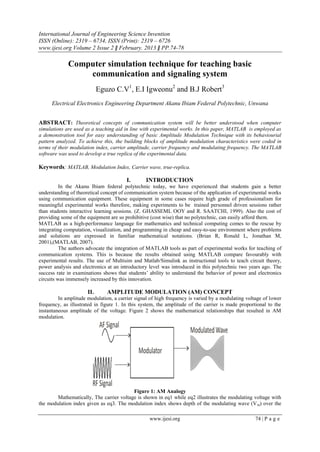
- 1. International Journal of Engineering Science Invention ISSN (Online): 2319 – 6734, ISSN (Print): 2319 – 6726 www.ijesi.org Volume 2 Issue 2 ǁ February. 2013 ǁ PP.74-78 www.ijesi.org 74 | P a g e Computer simulation technique for teaching basic communication and signaling system Eguzo C.V1 , E.I Igweonu2 and B.J Robert3 Electrical Electronics Engineering Department Akanu Ibiam Federal Polytechnic, Unwana ABSTRACT: Theoretical concepts of communication system will be better understood when computer simulations are used as a teaching aid in line with experimental works. In this paper, MATLAB is employed as a demonstration tool for easy understanding of basic Amplitude Modulation Technique with its behaviourial pattern analyzed. To achieve this, the building blocks of amplitude modulation characteristics were coded in terms of their modulation index, carrier amplitude, carrier frequency and modulating frequency. The MATLAB software was used to develop a true replica of the experimental data. Keywords: MATLAB, Modulation Index, Carrier wave, true-replica. I. INTRODUCTION In the Akanu Ibiam federal polytechnic today, we have experienced that students gain a better understanding of theoretical concept of communication system because of the application of experimental works using communication equipment. These equipment in some cases require high grade of professionalism for meaningful experimental works therefore, making experiments to be trained personnel driven sessions rather than students interactive learning sessions. (Z. GHASSEML OOY and R. SAATCHI, 1999). Also the cost of providing some of the equipment are so prohibitive (cost wise) that no polytechnic, can easily afford them. MATLAB as a high-performance language for mathematics and technical computing comes to the rescue by integrating computation, visualization, and programming in cheap and easy-to-use environment where problems and solutions are expressed in familiar mathematical notations. (Brian R, Ronald L, Jonathan M, 2001),(MATLAB, 2007). The authors advocate the integration of MATLAB tools as part of experimental works for teaching of communication systems. This is because the results obtained using MATLAB compare favourably with experimental results. The use of Multisim and Matlab/Simulink as instructional tools to teach circuit theory, power analysis and electronics at an introductory level was introduced in this polytechnic two years ago. The success rate in examinations shows that students’ ability to understand the behavior of power and electronics circuits was immensely increased by this innovation. II. AMPLITUDE MODULATION (AM) CONCEPT In amplitude modulation, a carrier signal of high frequency is varied by a modulating voltage of lower frequency, as illustrated in figure 1. In this system, the amplitude of the carrier is made proportional to the instantaneous amplitude of the voltage. Figure 2 shows the mathematical relationships that resulted in AM modulation. Figure 1: AM Analogy Mathematically, The carrier voltage is shown in eq1 while eq2 illustrates the modulating voltage with the modulation index given as eq3. The modulation index shows depth of the modulating wave (Vm) over the
- 2. Computer Simulation Technique For Teaching Basic Communication And Signaling System www.ijesi.org 75 | P a g e carrier wave (Vc). This figure ranges between 0 and 1, Over-modulation occurs when it exceeds 1 resulting in signal distortion because the amplifier is driven beyond set capacity. 𝑣𝑐 = 𝑉𝑐 𝑠𝑖𝑛𝜔𝑐 𝑡 − − − − − − − −𝑒𝑞1 𝑣 𝑚 = 𝑉𝑚 𝑠𝑖𝑛𝜔 𝑚 𝑡 − − − − − − − −𝑒𝑞2 𝑚 = 𝑉𝑚 𝑉𝑐 − − − − − − − − − − − 𝑒𝑞3 Figure 2: Modulated AM Wave III. MATLAB STUDY OF AMPLITUDE MODULATION We have tried to illustrate most experimental conditions of AM using MATLAB. Shown in figure 3 are the resulting waveforms, code declarations and mathematical computation of basic amplitude modulation characteristics. (a) (b) Figure 3: (a) Modulating wave. (b) Carrier Wave v +v sinw tc m m -(v +v sinw t)c m m Vc Vmin Vmax Vm Vm t0 V + - 0 0.01 0.02 0.03 0.04 0.05 0.06 0.07 0.08 0.09 0.1 -0.8 -0.6 -0.4 -0.2 0 0.2 0.4 0.6 0.8 Modulating Wave time amplitude 0 0.01 0.02 0.03 0.04 0.05 0.06 0.07 0.08 0.09 0.1 -1 -0.8 -0.6 -0.4 -0.2 0 0.2 0.4 0.6 0.8 1 Carrier Wave time amplitude
- 3. Computer Simulation Technique For Teaching Basic Communication And Signaling System www.ijesi.org 76 | P a g e (c) (d) Figure 3 (c) MATLAB Code (d) Modulated Wave The effect of modulation index is shown in figure 4 with different modulation indexes. The resulting AM signal with 100% modulation index and the MATLAB code are shown in figure 4a and 4b. The spectrum consists of 1000Hz carrier frequency with 30Hz modulating frequency. This result condition is replicated in 30% modulation except for changes in the modulating and carrier amplitude as shown in figure 4c and 4d. 0 0.01 0.02 0.03 0.04 0.05 0.06 0.07 0.08 0.09 0.1 -2 -1.5 -1 -0.5 0 0.5 1 1.5 2 AM waveform time amplitude
- 4. Computer Simulation Technique For Teaching Basic Communication And Signaling System www.ijesi.org 77 | P a g e Figure 4a: 100% Modulation index Figure 4b: Sample code for 100% Modulation Figure 4c: 30% Modulation Figure 4d: Sample code for 30% Modulation Figure 4c: 200% Overmodulation Figure 4b: Sample code for 200% Over-Modulation When the modulation index (m) is greater than one, over-modulation occurs which leads to signal distortion as shown in figure 4c. (UNESCO-NBTE, 2008). 0 0.01 0.02 0.03 0.04 0.05 0.06 0.07 0.08 0.09 0.1 -2 -1.5 -1 -0.5 0 0.5 1 1.5 2 AM waveform time amplitude 0 0.01 0.02 0.03 0.04 0.05 0.06 0.07 0.08 0.09 0.1 -1.5 -1 -0.5 0 0.5 1 1.5 AM waveform time amplitude 0 0.01 0.02 0.03 0.04 0.05 0.06 0.07 0.08 0.09 0.1 -3 -2 -1 0 1 2 3 AM waveform time amplitude
- 5. Computer Simulation Technique For Teaching Basic Communication And Signaling System www.ijesi.org 78 | P a g e IV. CONCLUSION In this paper, the authors have used MATLAB programming language to demonstrate how amplitude modulation can be simulated and studied outside the laboratory. This approach is very useful for teaching and learning of communication systems and other related areas. From the case study, the effectiveness of Matlab on more complex for teaching and research cannot be over-emphasized. The processes used here could very profitably be employed in the analysis of any signaling system. REFERENCES [1]. Brian R. Hunt, Ronald L. Lipsman, [2]. Jonathan M. Rosenberg (2001); A guide [3]. to MATLAB for beginners and experienced users, New York USA Cambridge University Press. [4]. MATLAB (2007); The language of Technical Computing, The Math Works, Inc.(U.S) UNESCO- Nigeria Technical & Vocational Education Revitalization Project Phase II (Dec, 2008); National Diploma in Electrical Engineering Technology Practical. UNESCO-NBTE. Z. GHASSEML OOY and R. SAATCHI (1999); [5]. Software Simulation Techniques For Teaching Communication Systems, Manchester U.P., Great Britain, Int. J. Elect. Enging. Educ., Vol. 36, pp. 287–297.