El documento lista diferentes modelos de cortadoras Eclipse 2 con diferentes tamaños de cuchillas y opciones de motor como generador o batería. También incluye advertencias de seguridad y una lista de piezas de repuesto y materiales de apoyo recomendados.


![CONTROLS 4
19
4.3 LCD DISPLAY_____________________________________________________________
The LCD displays current functional values for the
operation of the Eclipse 2 mower and sounds one of
three types of audible alerts. The LCD operates in one of
two modes, Operator Mode (Default), and Maintenance
Mode. Use of Maintenance mode requires a four digit pin
number.
Press either of the orange buttons (K or L) to change
screen display or change values. Push the right orange
button (K) to go forward in the display list or increase
setting value, and push the left orange button (L) to go
back in the display list or decrease setting value. The
black button (J) is used to select, reset, or change
values.
Figure 4B
Audible Alerts indicate one of three conditions detected
by the LCD Display and a corresponding message would
show on the display. A solid tone indicates low system
voltage. A fast beeping (2 per second) alert indicates an
over voltage condition. A slow beeping (1 every 3
seconds) alert indicates mower is in backlap mode.
Alert Displays: In addition to the standard displays for each mode, there are six displays that are used to alert the
operator/mechanic of a problem the needs to be corrected.
G
J
K
L
Alert Display Alert Description
Low Voltage display is shown when system voltage drops below 42 Volts DC on Battery
powered mowers or 38 Volts DC on Gen-Set powered mowers, for 30 seconds and a solid tone
alarm will sound. Press the black button (J) to silence the alarm. Return mower to storage area
or install a fully charged battery pack. Reel motor will not operate with low voltage on the display.
Overvoltage/Check Voltage display is shown when system voltage is above 60 Volts DC and a
fast (2 per second) beeping alarm will sound. If not corrected, controller will shut down after 60
seconds. Check generator output before restarting system. [See Section 11.4].
Traction Motor Controller Fault display is shown when a problem is detected in the traction
motor controller. Traction motor will not operate until the problem is resolved. Return mower to
maintenance area for repair.
Traction Motor Fault display is shown when a traction motor short circuit is detected or the
traction motor current draw exceeds 30 Amps for one second. Traction motor will not operate
until the problem is resolved. Return mower to maintenance area for repair.
Reel Motor Controller Fault display is shown when a problem is detected in the reel motor
controller. Reel motor will not operate until the problem is resolved. Return mower to
maintenance area for repair.
Reel Motor Fault display is shown when a reel motor short circuit is detected or the reel motor
current draw exceeds 30 Amps for one second. Reel motor will not operate until the problem is
resolved. Return mower to maintenance area for repair.
WARNING
Turn reel switch off, release bail, turn key to off position, and disconnect battery connector before checking for
obstructions in reel.
!](https://image.slidesharecdn.com/eclipce2-210721150107/85/Eclipce-2-19-320.jpg)

![4 CONTROLS
22
Display Description
To enter Maintenance Mode, press either orange buttons (K or L) until Maintenance Mode PIN
screen is on the display and press black button (J). Use the orange buttons (K or L) to select and
the black button (J) to enter the digits for the Mechanic Mode pin.
NOTE: The default PIN for Maintenance Mode is 6789. The Maintenance Mode PIN can be
customized to a setting of your choice. Please contact your Jacobsen Dealer or Jacobsen
Technical Support (1800-848-1636 Option 2) for complete instructions.
Maintenance Hours - System can track up to 999.9 hours for maintenance purposes.
To reset maintenance hours, press either of the orange buttons (K or L) on the front cover until
the maintenance hours screen is on the LCD display. Press the black button (J) to move to the
confirm reset screen. Press the right orange button (K) to confirm reset, or press left orange
button (L) to cancel reset.
Backlap Select - Used to switch mower to backlap mode. See Section 12.4 for backlap screen
descriptions.
Set FOC - To set the fixed FOC, press either of the orange buttons (K or L) on the front cover
until the FOC set screen is on the LCD display. Press the black button (J) to enter set mode. Use
the orange buttons to raise (K) or lower (L) the FOC value to the desired setting. press the black
button to set speed.
Fixed FOC setting must be 0 or between 0.087 and 0.178 in. (2.2 and 4.5 mm). [See Section
4.4].
Traction Motor Current - Displays current draw of traction drum motor. Fault will be displayed if
current draw is greater than 30 Amps for one second.
Reel Motor Current - Displays current draw of reel motor. Fault will be displayed if current draw
is greater than 30 Amps for one second.
Total Motor Current - Displays total current draw of traction drum motor and reel motor.
Maximum Mow Speed - To set the maximum mow speed, press either of the orange buttons (K
or L) on the front cover until the set max mow speed screen is on the LCD display. Press the
black button (J) to enter set mode. Use the orange buttons to raise (K) or lower (L) the maximum
mow speed to the desired speed. press the black button to set speed.
Maximum mow speed must be between 2.0 and 3.8 MPH (3.2 and 6.1 kph).
Fixed Reel Speed: To set the fixed reel speed, the FOC setting must be set to 0, then press
either of the orange buttons (K or L) on the front cover until the set reel speed screen is on the
LCD display. Press the black button (J) to enter set mode. Use the orange buttons to raise (K) or
lower (L) the reel speed to the desired setting.
Fixed reel speed must be set between 1800 and 2200 rpm.
The Maximum Mow Speed and the Fixed Reel Speed are used to determine the FOC
(Frequency of Cut) [See Section 4.4].](https://image.slidesharecdn.com/eclipce2-210721150107/85/Eclipce-2-22-320.jpg)
![CONTROLS 4
23
Gen-Set Power Module - Used to indicate the gen-set power module is installed on the mower.
This setting is used by system controllers and does not affect operation of mower. Do not
operate mower with incorrect power module setting. Press the black button (J) to toggle
between the power module settings.
Battery Power Module - Used to indicate the battery power module is installed on the mower.
This setting is used by system controllers and does not affect operation of mower. Do not
operate mower with incorrect power module setting. Press the black button (J) to toggle
between the power module settings.
Set Number of Reel Blades: To set the number of reel blades, press either of the orange
buttons (K or L) on the front cover until the reel blades screen is on the LCD display. Press the
black button (J) to enter set mode. Use the orange buttons to set the number of blades.
Available reel blades are 7, 9 (Floating Only), 11 or 15.
Speed Paddle Calibration - Before calibrating the speed paddle, check that paddle stops are
properly adjusted [See Section 6.3].To calibrate the paddle, press either of the orange buttons
(K or L) on the front cover until the speed paddle calibration screen is on the LCD display. Press
the black button (J) to enter set mode. Move the speed paddle through its entire range of
movement to determine minimum and maximum values.
Values displayed will change as controls are moved.
Bail Lever Calibration - To calibrate the bail lever, press either of the orange buttons (K or L) on
the front cover until the bail lever calibration screen is on the LCD display. Press the black button
(J) to enter set mode. Fully engage and disengage the bail lever to determine minimum and
maximum values.
Values displayed will change as controls are moved.
Display Units - To set the display units, press either of the orange buttons (K or L) on the front
cover until the units screen is on the LCD display. Press the black button (J) to toggle between
english (MPH, IN) or metric (KPH, mm) units.
Factory Reset - To reset controller to factory default values, press either of the orange buttons
(K or L) on the front cover until the Factory Reset screen is on the LCD display. Press the black
button (J) to move to the confirm reset screen. Press the right orange button (K) to confirm reset,
or press left orange button (L) to cancel reset.
Maximum Mow Speed......3.4 Mph (5.5 kph)
Reel Speed ......................2200 rpm
Fixed FOC Setting............0.146
Display units.....................English
Display Description](https://image.slidesharecdn.com/eclipce2-210721150107/85/Eclipce-2-23-320.jpg)
![4 CONTROLS
24
4.4 FREQUENCY OF CUT ______________________________________________________
The FOC (Frequency of cut) is the distance, in inches
(mm), the machine travels forward between reel blades
contacting the bedknife. The FOC can be adjusted either
by changing the Fixed FOC setting or by changing the
maximum mow speed and the fixed reel speed on the
LCD display.
Adjust FOC with Fixed FOC setting
Changing the FOC setting to a value other than 0 will
enable the fixed FOC mode and disable the reel speed
setting. As mower travel speed increases or decreases,
reel speed will automatically adjust as required to
maintain set FOC.
Adjust FOC with Reel Speed Setting
1. Using the FOC charts, determine the maximum mow
speed and fixed reel speed required for the desired
FOC.
2. Start the unit in Maintenance mode. [Section 4.3]
3. Set fixed FOC setting to 0
4. Set desired Maximum Mow Speed
5. Set desired Fixed Reel Speed
NOTE: Mow speed is measured in mph (kph), FOC is
measured in inches (millimeters).](https://image.slidesharecdn.com/eclipce2-210721150107/85/Eclipce-2-24-320.jpg)


![OPERATION 5
33
5.5 MOWING _________________________________________________________________
1. Turn power OFF. Remove the transport wheels (If
installed).
2. Engage the reel switch. Start the unit.
3. Position mower slightly off green.
a. Adjust traction speed paddle (B) to provide a
safe, comfortable walking speed.
b. Push handle down to lift the mower head above
the grass then engage the O.P.C. bail (C).
c. As the mower crosses the edge of the green,
lower the mower head to the ground, and
proceed across the green in a straight line.
When mowing lift up as required to keep handle
centered in slots on handle stops. Do not push
down on handle when mowing or the mower
head may lift off the grass.
d. When the opposite side of the green is reached,
push down of the handle to lift the mower head
without disengaging the O.P.C. bail, and proceed
off the green to turn around, or simply release
O.P.C. bail and turn around.
e. To turn to the right, start by turning mower slightly
to the left (2). When the mower has moved
approximately 1/2 its own width to the left, swing
it around quickly to the right (3 and 4), guiding
the mower with your right hand. This method
makes it possible to turn around quickly with very
few steps. [Figure 5C].
4. To assure complete, even cutting, overlap swaths by
1 to 2 in., (25 to 50 mm), then make one or more
passes around the perimeter of the green to clean
ragged edges and separate the putting green
surface from the apron.
5. For a more even playing surface and neater
appearance, alter the mowing pattern each time a
green is mowed. The patterns shown in Figure 5D
are suggestions only, the operator or course
superintendent can arrange patterns to suit each
green.
6. Use caution while operating on hillside and drop-
offs.
Figure 5C
Figure 5D
WARNING
To prevent serious injuries, keep hands, feet, and
clothing away from cutting unit when the blades are
moving.
NEVER use your hands to clean cutting units. Use a
brush to remove grass clippings from blades. Blades
can be sharp and could cause injuries.
To clear obstructions from cutting unit, disengage
O.P.C. bail, engage parking brake, turn off power
switch, and disconnect power connector then remove
obstruction.
NOTICE
To prevent damage to the reel and bedknife never
operate the reels when they are not cutting grass.
Excessive friction and heat will develop between the
bedknife and reel and damage the cutting edge.
!
1
2
3
4
5
First
Mowing
Second
Mowing
Third
Mowing
Fourth
Mowing](https://image.slidesharecdn.com/eclipce2-210721150107/85/Eclipce-2-33-320.jpg)


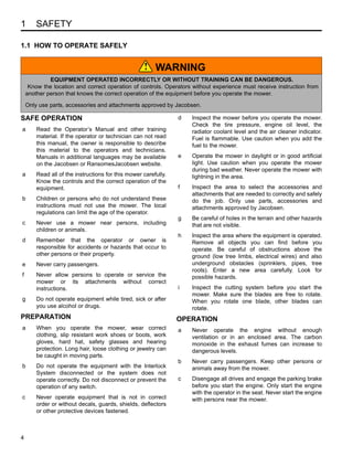
![6 ADJUSTMENTS (ALL UNITS)
36
6 ADJUSTMENTS (ALL UNITS)
6.1 GENERAL________________________________________________________________
1. Adjustments and maintenance should always be
performed by a qualified technician. If proper
adjustment cannot be made, contact an authorized
Jacobsen Dealer.
2. Replace, do not adjust, worn or damaged
components.
3. Long hair, jewelry, or loose fitting clothing may get
tangled in moving parts.
4. Do not change speed limit settings or overspeed the
drive motors.
6.2 BRAKE __________________________________________________________________
A properly adjusted brake requires 10 lbs. pull at top of
brake lever to engage and must have 1-1/2” (38 mm)
center to center when released.
1. Minor adjustments are made at the handle. Loosen
nut (A), turn nut (B) to adjust the brake cable, then
tighten nut (A).
2. If adjustments cannot be made at the handle,
remove the transport wheel, and make the
adjustment at the brake band.
3. Loosen screw (C) and pull cable to obtain desired
brake tension. Tighten screw (C). Readjust (A) and
(B).
Figure 6A
6.3 SPEED PADDLE STOPS ____________________________________________________
1. Loosen both nuts (X).
2. Adjust positive paddle stop (Y) to 7/8 in. (22 mm).
3. Adjust negative paddle stop (Z) to 1-1/16 in. (27
mm).
4. Tighten nuts (X) to lock adjustment.
After adjusting paddle stops, the controller speed paddle
calibration must be reset. [See Section 4.3].
Figure 6B
WARNING
Before you adjust, clean, or repair this equipment,
always disengage all drives, engage parking brake,
turn key switch OFF, and disconnect power connector
to prevent serious injury.
!
CAUTION
Be careful to prevent entrapment of the hands and
fingers between moving and fixed components of the
machine.
!
HANDLE
BRAKE BAND
A
B
C
1-1/2”
(38 mm)
1-1/16 in.
(27 mm)
7/8 in.
(22 mm)
X
Y
Z](https://image.slidesharecdn.com/eclipce2-210721150107/85/Eclipce-2-36-320.jpg)


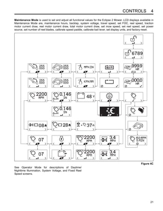
![FIXED HEAD REEL ADJUSTMENTS 7
41
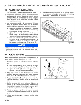
7.3 BEDKNIFE ADJUSTMENT ___________________________________________________
1. Adjuster (A) is used to increase or decrease the
spring load on the bedknife. Adjuster (B) is used to
move the bedknife to the reel or away from the reel.
2. Once the spring is totally collapsed as a result of
many adjustments, the bedknife cannot be moved.
Back-off adjuster (A) before adjusting (B).
3. For most applications, compress the spring to 1 in.,
(25 mm).
4. Start adjustment at the leading edge of the reel,
followed by the trailing end. The leading end of the
reel blade is the end that passes over the bedknife
first during normal rotation.
5. Turn adjuster (B) clockwise to bring the bedknife
closer to the reel or counterclockwise to back the
bedknife away from the reel.
a. Slide a feeler gauge or shim stock 0.001 - 0.003
in., (0.025 - 0.075 mm) between the reel blade
and the bedknife. Do not turn the reel.
b. Adjust the trailing end of the reel in the same
manner, then recheck the adjustment at the
leading end.
c. When the reel and bedknife are properly
adjusted, the reel will spin freely and will cut a
piece of newspaper along the full length of the
reel when the paper is held at 90° to the
bedknife.
Figure 7B
Figure 7C
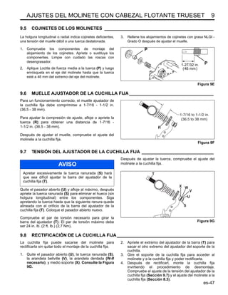
7.4 CUTTING HEIGHT _________________________________________________________
Note: Make sure the bedknife is properly adjusted before
setting the cutting height. [See Section 7.3].
1. Push kickstand down and tip mower back on it’s
handle.
2. Loosen nuts (D) on both sides just enough to allow
knob (C) to raise the front roller. Raise both sides an
equal amount.
3. Set gauge screw (G) to the desired cutting height
(F). Measure from the gauge bar (E) to the
underside of the screw head (G) then tighten wing
nut to lock the adjustment.
4. Place gauge bar between front roller and traction
roller, near the outer end of the rollers.
5. Slide screw head over bedknife (H) and adjust knob
(C) so roller just contacts the gauge bar. Tighten nut
(D).
6. Repeat Steps 4 and 5 on the opposite end of the
reel then tighten nuts (D). Recheck and readjust the
cutting height if necessary.
Figure 7D
NOTICE
Before tipping mower back for adjustments, the fuel
lever must be moved to the OFF position to prevent
fuel from leaking into the crankcase.
CAUTION
Handle the reel with extreme care to prevent personal
injury and damage to the cutting edges.
!
Rotation
Leading Edge
A
B
NOTICE
Gen-Set Power Modules: Do not leave the mower
tipped back for an extended length of time or oil may
migrate into the combustion chamber.
C
D
E F G H](https://image.slidesharecdn.com/eclipce2-210721150107/85/Eclipce-2-41-320.jpg)


![12 MAINTENANCE
58
12.4 BACKLAPPING AND GRINDING _____________________________________________
Check for damage to the bedknife and reel blades.
Refer to (Section 6.2).
1. Determine if backlapping or grinding will restore the
proper cutting edge.
2. For optimum performance use a bedknife grinder to
touch-up the blade then reassemble and adjust the
bedknife to the reel as described in (Section 6.2).
Disconnect motor connections whenever turning the
reel by means other than the reel motor. When
tightening, hand tighten motor connections only,
do not use wrenches to tighten motor
connection.
Figure 12B
3. Apply lapping compound with a long handle brush
along the entire length of the reel, (180 grit is
recommended, Section 2.7).
4. Continue lapping and at the same time make a fine
adjustment on the reel and bedknife until there is a
uniform clearance along the full length of the cutting
edges.
5. Exit backlap mode by allowing the five minute timer
to end, selecting Cancel (Ø), placing reel switch (E)
in the OFF position, moving the O.P.C. bail (C),
moving the thumb lever (B), or turning key switch
(D) to the OFF position.
6. Turn key switch (D) to off position.
7. Carefully and thoroughly remove all lapping
compound from reel and bedknife before running
the reel in forward direction.
A
F
G
H
E
B
C
D
Backlap Display Description
Backlap Select - Used to switch mower into backlap mode. Start the mower and enter
Maintenance mode. [See Section 4.3]
Use the orange buttons (G or H) until the select backlap screen is on the display. Press the
black button (F) to enter backlap mode.
Engage Reel Switch - To backlap, place reel switch (E) in ON position. If Cancel (Ø) is
selected, display will return to backlap select screen.
Engage Bail - Engage O.P.C. bail (C) and release. Reel motor will begin turning, a slow beeping
(1 every three seconds) alarm will sound and a five minute timer will start. If Cancel (Ø) is
selected, display will return to backlap select screen.
Backlap Reel Speed and Timer Adjust reel speed between 150 to 400 rpm using the orange
buttons (G or H). Press the black button (F) to Cancel (Ø) backlap.](https://image.slidesharecdn.com/eclipce2-210721150107/85/Eclipce-2-58-320.jpg)


![CONTROLES 4
es-19
4.3 MONITOR LCD ____________________________________________________________
El monitor LCD muestra valores funcionales actuales para
el funcionamiento del cortacésped Eclipse 2 y hace sonar
uno de los tres tipos de alertas. El monitor LCD tiene dos
modos de funcionamiento: Modo Operario (predeterminado)
y Modo Encargado. El uso en Modo Encargado requiere
introducir un número PIN de cuatro dígitos.
Pulse cualquiera de los botones naranjas (K o L) para
cambiar la apariencia de la pantalla o cambiar los valores.
Pulse el botón naranja derecho (K) para desplazarse hacia
delante en la lista o aumentar el valor, y pulse el botón
naranja izquierdo (L) para volver a la lista o disminuir el
valor de ajuste. El botón negro (J) se utiliza para
seleccionar, restablecer o cambiar los valores.
Figura 4B
Alertas sonoras: Indican una de las tres condiciones
detectadas por el monitor LCD y aparece en el monitor el
mensaje correspondiente. Un tono constante indica bajo
voltaje del sistema. Una alerta sonora rápida (2 por
segundo) alerta de una condición de sobrevoltaje. Una
alerta sonora lenta (1 cada 3 segundos) indica que el
cortacésped está en modo de esmerilado.
Pantallas de alerta: Además de las pantallas estándar para cada modo, existen cuatro pantallas utilizadas para alertar al
operario/mecánico de un problema que debe solucionarse.
G
J
K
L
Pantalla de alerta: Descripción de la alerta
La pantalla Voltaje bajo aparece cuando el voltaje del sistema baja por debajo de 42 V CC en
cortacéspedes alimentados por baterías o 38 V CC en cortacéspedes alimentados con bloque generador
durante 30 segundos y suena un tono de alarma. Pulse el botón negro (J) para silenciar la alarma. Lleve el
cortacésped a la zona de almacenamiento o instale una batería totalmente cargada. El motor del molinete
no funcionará con la alerta de voltaje bajo en la pantalla.
La pantalla Sobrevoltaje/Comprobar voltaje aparece y suena una alarma intermitente rápida (2 por
segundo) cuando el voltaje del sistema supera los 60 V CC. Si no se corrige, el controlador se apaga
después de 60 segundos. Compruebe la salida del generador antes de reiniciar el sistema. [Ver Sección
11.4].
La pantalla Fallo del controlador del motor de tracción aparece cuando se detecta un problema en el
controlador del motor de tracción. El motor de tracción no funcionará hasta que se resuelva el problema.
Lleve el cortacésped a la zona de mantenimiento para ser reparado.
La pantalla Fallo del motor de tracción aparece cuando se detecta un cortocircuito en el motor de
tracción o su consumo de corriente es superior a 30 A por segundo. El motor de tracción no funcionará
hasta que se resuelva el problema. Lleve el cortacésped a la zona de mantenimiento para ser reparado.
La pantalla Fallo del controlador del motor de molinete aparece cuando se detecta un problema en el
controlador del motor del molinete. El motor del molinete no funcionará hasta que se resuelva el problema.
Lleve el cortacésped a la zona de mantenimiento para ser reparado.
La pantalla Fallo del motor del molinete aparece cuando se detecta un cortocircuito en el motor del
molinete o su consumo de corriente es superior a 30 A por segundo. El motor del molinete no funcionará
hasta que se resuelva el problema. Lleve el cortacésped a la zona de mantenimiento para ser reparado.
ADVERTENCIA
Apague el molinete, suelte la palanca, ponga la llave en la posición de apagado y desconecte el conector de la
batería para comprobar si hay alguna obstrucción en el molinete.
!](https://image.slidesharecdn.com/eclipce2-210721150107/85/Eclipce-2-81-320.jpg)

![4 CONTROLES
es-22
Pantalla Descripción
Para entrar en el Modo de mantenimiento, pulse alguno de los botones naranjas (K o L) hasta que
aparezca en la pantalla PIN de Modo de mantenimiento y a continuación pulse el botón negro (J). Use los
botones naranjas (K o L) para seleccionar y el botón negro (J) para introducir los dígitos del PIN en Modo
Mecánico.
NOTA: El PIN predeterminado para el modo Mantenimiento es 6789. El PIN del modo Mantenimiento
puede ser personalizado a su elección. Póngase en contacto con su distribuidor Jacobsen o con el servicio
de asistencia técnica de Jacobsen (teléfono 1800-848-1636 Opción 2) para recibir instrucciones completas.
Horas de mantenimiento - El sistema puede registrar hasta 999,9 horas para mantenimiento.
Para establecer las horas de mantenimiento, pulse alguno de los botones naranjas (K o L) de la tapa
delantera hasta que aparezca la pantalla de horas de mantenimiento en el monitor LCD. Pulse el botón
negro (J) para pasar a la pantalla de confirmación de reajuste. Pulse el botón naranje derecho (K) para
confirmar el reajuste o el botón naranje izquierdo (L) para cancelarlo.
Seleccionar esmerilado - Se utiliza para poner el cortacésped en modo de esmerilado. Consulte la
Sección 12.4 para ver descripciones de las pantallas de esmerilado.
Establecer frecuencia de corte (FOC) - Para establecer la frecuencia de corte fija, pulse alguno de los
botones naranjas (K o L) de la tapa delantera hasta que aparezca la pantalla de ajuste de frecuencia de
corte en el monitor LCD. Pulse el botón negro (J) para entrar en modo de ajuste. Use los botones naranjas
para aumentar (K) o disminuir (L) el valor FOC hasta el ajuste deseado, y a continuación pulse el botón
negro para establecer la velocidad.
El ajuste de frecuencia de corte fija debe ser 0 o estar entre 2,2 y 4,5 mm. [Ver Sección 4.4].
Corriente del motor de tracción - Muestra la corriente del motor del tambor de tracción. Si la corriente es
mayor de 30 A durante un segundo aparecerá una avería.
Corriente del motor del molinete - Muestra la corriente del motor del molinete. Si la corriente es mayor
de 30 A durante un segundo aparecerá una avería.
Corriente total del motor - Muestra la corriente total del motor del tambor de tracción y del molinete.
Velocidad de corte máxima - Para establecer la velocidad de corte máxima, pulse alguno de los botones
naranjas (K o L) de la tapa delantera hasta que aparezca la pantalla de establecimiento de velocidad de
corte máxima en el monitor LCD. Pulse el botón negro (J) para entrar en modo de ajuste. Use los botones
naranjas para aumentar (K) o disminuir (L) la velocidad de corte máxima, y a continuación pulse el botón
negro para establecer la velocidad.
La velocidad de corte máxima debe estar entre 3,2 y 6,1 km/h.
Velocidad del molinete fijo: Para establecer la velocidad del molinete fijo, el ajuste FOC debe estar en 0,
y después debe pulsar alguno de los botones naranjas (K o L) de la tapa delantera hasta que aparezca la
pantalla VELOCIDAD molinete en el monitor LCD. Pulse el botón negro (J) para entrar en modo de ajuste.
Use los botones naranjas para aumentar (K) o disminuir (L) la velocidad del molinete.
La velocidad del molinete debe estar entre 1800 y 2200 rpm.
La velocidad de corte máxima y la velocidad del molinete fijo se utilizan para determinar el ajuste FOC
(frecuencia de corte) [Ver Sección 4.4].](https://image.slidesharecdn.com/eclipce2-210721150107/85/Eclipce-2-84-320.jpg)
![CONTROLES 4
es-23
Módulo de encendido con bloque generador - Se utiliza para indicar que está instalado el módulo de
encendido con bloque generador en el cortacésped. Este ajuste lo utilizan los controladores del sistema y
no afecta al funcionamiento del cortacésped. No utilice el cortacésped con un ajuste incorrecto del módulo
de encendido. Pulse el botón negro (J) para cambiar entre los ajustes del módulo de encendido.
Módulo de encendido con baterías - Se utiliza para indicar que está instalado el módulo de encendido
con baterías en el cortacésped. Este ajuste lo utilizan los controladores del sistema y no afecta al
funcionamiento del cortacésped. No utilice el cortacésped con un ajuste incorrecto del módulo de
encendido. Pulse el botón negro (J) para cambiar entre los ajustes del módulo de encendido.
Ajustar número de cuchillas por molinete: Para cajustar el número de cuchillas por molinete, pulse
alguno de los botones naranjas (K o L) de la tapa delantera hasta que aparezca la pantalla de cuchillas por
molinete en el monitor LCD. Pulse el botón negro (J) para entrar en modo de ajuste. Utilice los botones
naranjas para ajustar el número de cuchillas.
El número de cuchillas por molinete disponibles es 7, 9 (flotantes únicamente), 11 o 15.
Calibración de la palanca de velocidad - Antes de calibrar la palanca de velocidad, compruebe que los
topes de la palanca estén bien ajustados [Ver Sección 6.3]. Para calibrar la palanca, pulse alguno de los
botones naranjas (K o L) en la tapa delantera hasta que aparezca la pantalla de calibración de la palanca
de velocidad en el monitor LCD. Pulse el botón negro (J) para entrar en modo de ajuste. Mueva la palanca
de velocidad todo el recorrido de la misma para determinar los valores mínimo y máximo.
Los valores mostrados cambian a medida que se mueven los controles.
Calibración de la palanca OPC - Para calibrar la palanca OPC, pulse alguno de los botones naranjas (K o
L) de la tapa delantera hasta que aparezca la pantalla de calibración de la palanca OPC en el monitor LCD.
Pulse el botón negro (J) para entrar en modo de ajuste. Presione y suelte la palanca OPC para determinar
los valores máximo y mínimo.
Los valores mostrados cambian a medida que se mueven los controles.
Unidades de la pantalla - Para establecer las unidades de la pantalla, pulse alguno de los botones
naranjas (K o L) de la tapa delantera hasta que aparezca la pantalla de unidades en el monitor LCD. Pulse
el botón negro (J) para cambiar entre unidades imperiales (mph, in) o métricas (km/h, mm).
Reajuste de fábrica - Para reajustar el controlador con los ajustes de fábrica, pulse alguno de los botones
naranjas (K o L) de la tapa delantera hasta que aparezca la pantalla de reajuste de fábrica en el monitor
LCD. Pulse el botón negro (J) para pasar a la pantalla de confirmación de reajuste. Pulse el botón naranje
derecho (K) para confirmar el reajuste o el botón naranje izquierdo (L) para cancelarlo.
Velocidad de corte máxima ......5,5 km/h
Velocidad de los molinetes.......2200 RPM
Ajuste FOC fijo .........................0,146
Unidades de la pantalla ............Inglés
Pantalla Descripción](https://image.slidesharecdn.com/eclipce2-210721150107/85/Eclipce-2-85-320.jpg)
![4 CONTROLES
es-24
4.4 FRECUENCIA DE CORTE ___________________________________________________
El ajuste FOC (frecuencia de corte) es la distancia en mm
que recorre la máquina entre contacto y contacto de las
cuchillas del molinete con la cuchilla fija. El ajuste FOC
puede realizarse cambiando el ajuste FOC fijo o cambiando
la velocidad de corte máxima y la velocidad del molinete fijo
en el monitor LCD.
Ajuste FOC con ajuste FOC fijo
Cambiar el ajuste FOC a un valor distinto de 0 habilita el
modo FOC fijo e inhabilita el ajuste de velocidad del
molinete. A medida que aumenta o disminuye la velocidad
del cortacésped, la velocidad del molinete se ajusta
automáticamente lo necesario para mantener la frecuencia
de corte establecida.
Conversión de 9 cuchillas.......0,81818 (9/11)
Conversión de 7 cuchillas.......0,63636 (7/11)
Ajustar FOC con ajuste de velocidad de molinete
1. Usando los cuadros de frecuencia de corte, determine
la velocidad de corte máxima y la velocidad del
molinete fijo necesarias para la frecuencia de corte
deseada.
2. Encienda la unidad en modo Encargado. [Sección
4.3]
3. Establezca el ajuste FOC a 0.
4. Ajuste la velocidad de corte máxima.
5. Ajuste la velocidad del molinete fijo deseada.
Nota: La velocidad de corte se mide en mph (km/h), el
ajuste FOC en pulgadas (milímetros).](https://image.slidesharecdn.com/eclipce2-210721150107/85/Eclipce-2-86-320.jpg)


![FUNCIONAMIENTO 5
es-33
5.5 CORTE __________________________________________________________________
1. Apague la máquina. Coloque el cortacésped sobre un
soporte y quite las ruedas de transporte (si están
instaladas).
2. Conecte el interruptor del molinete. Empuje el
cortacésped hacia delante para sacarlo del soporte.
Encienda la máquina.
3. Coloque el cortacésped ligeramente fuera del green.
a. Ajuste la palanca de velocidad de tracción (B) a
una velocidad lenta, segura y cómoda.
b. Empuje el manillar hacia abajo para levantar la
parte delantera del cortacésped y luego presione la
palanca OPC (C).
c. Cuando el cortacésped atraviese el borde del
green, baje su parte delantera al suelo y avance
por el green en línea recta.
Cuando corte, levante lo necesario para mantener
el manillar centrado en las ranuras o los topes. No
baje el manillar al cortar, de lo contrario la parte
delantera del cortacésped puede levantarse.
d. Cuando llegue al borde opuesto del green, empuje
hacia abajo el manillar para levantar la parte
delantera del cortacésped sin desactivar la palanca
OPC y siga avanzando fuera del green para dar
media vuelta o simplemente desactive la palanca
OPC y dé media vuelta.
e. Para girar a la derecha, gire el cortacésped
ligeramente a la izquierda (2). Cuando el
cortacésped se haya movido alrededor de la mitad
de su propia anchura a la izquierda, gírelo
rápidamente a la derecha (3 y 4), guiándolo con la
mano derecha. Este método permite girar
rápidamente en pocos pasos. [Figura 5C]
4. Para asegurar un corte completo y uniforme, solape
las pasadas unos 25 o 50 mm y luego haga una o más
pasadas en torno al perímetro del green para limpiar
los bordes desiguales y separar la superficie del
putting green del césped a su alrededor.
5. Para conseguir una superficie de juego más regular y
más atractiva, cambie el patrón de corte cada vez que
corte el césped del green. Los patrones mostrados en
la Figura 5D son sólo sugerencias, el operario o el
encargado pueden crear patrones adecuados para
cada green.
6. Tenga cuidado al trabajar en pendientes o terraplenes.
Figura 5C
Figura 5D
ADVERTENCIA
Para evitar lesiones graves, mantenga las manos, pies y
ropa alejados de la unidad de corte cuando las cuchillas
estén en movimiento.
NUNCA limpie las unidades de corte con las manos.
Utilice un cepillo para retirar los restos de hierba de las
cuchillas. Las cuchillas están extremadamente afiladas y
pueden causar lesiones graves.
Para limpiar las obstrucciones de la unidad de corte,
suelte la palanca OPC, ponga el freno de
estacionamiento, apague el interruptor de encendido y
desconecte el conector de encendido.
AVISO
Para evitar daños al molinete y a la cuchilla fija, no opere
nunca los molinetes cuando no estén cortando césped.
Producirá fricción y calor excesivos entre la cuchilla fija y
el molinete, causando desperfectos al borde de corte.
!
1
2
3
4
5
Primer
corte
Segundo
corte
Tercer
corte
Cuarto
corte](https://image.slidesharecdn.com/eclipce2-210721150107/85/Eclipce-2-95-320.jpg)


![6 AJUSTES (TODAS LAS UNIDADES)
es-36
6 AJUSTES (TODAS LAS UNIDADES)
6.1 GENERALIDADES _________________________________________________________
1. Los ajustes y las tareas de mantenimiento deben ser
realizadas siempre por un técnico cualificado. Si no
puede realizar el ajuste deseado, póngase en
contacto con un distribuidor Jacobsen autorizado.
2. Cambie, no ajuste, los componentes desgastados y
dañados.
3. El pelo largo, las joyas o la ropa suelta pueden
trabarse en las partes móviles.
4. No cambie los ajustes de límite de velocidad ni aplique
demasiada velocidad a los motores de tracción.
6.2 FRENO __________________________________________________________________
Un freno ajustado apropiadamente requiere una
resistencia de 4,5 kg en el vértice de la palanca del freno
para engranar, y debe haber una distancia de 38 mm de
centro a centro cuando se suelta.
1. Los ajustes menores se hacen en el manillar. Afloje
la tuerca (A), gire la tuerca (B) para ajustar el cable
del freno y apriete de nuevo la tuerca (A).
2. Si no puede hacer los ajustes en el manillar, quite
las ruedas de transporte y realice el ajuste en la
banda del freno.
3. Afloje el tornillo (C) y tire del cable hasta obtener la
tensión deseada en el freno. Apriete el tornillo (C).
Vuelva a ajustar (A) y (B).
Figura 6A
6.3 TOPES DE LA PALANCA DE VELOCIDAD _____________________________________
1. Afloje las tuercas (X).
2. Ajuste el tope positivo de la palanca (Y) a 22 mm.
3. Ajuste el tope negativo de la palanca (Z) a 27 mm.
4. Apriete las tuercas (X) para fijar el ajuste.
Despuñes de ajustr los topes de la palanca, debe
reajustarse la calibración de la palanca de velocidad del
controlador. [Ver Sección 4.3]
Figura 6B
ADVERTENCIA
Para impedir lesiones graves, antes de ajustar,
limpiar o reparar este equipo, desactive todas las
transmisiones, ponga el freno de estacionamiento y
apague el motor y desconecte el conector d
encendido.
!
PRECAUCIÓN
Tenga cuidado para evitar que las manos y los dedos
queden atrapados entre los componentes móviles y
fijos de la máquina.
!
MANILLAR
BANDA DEL FRENO
A
B
C
38 mm
1-1/16 in.
(27 mm)
7/8 in.
(22 mm)
X
Y
Z](https://image.slidesharecdn.com/eclipce2-210721150107/85/Eclipce-2-98-320.jpg)


![12 MANTENIMIENTO
es-58
12.4 ESMERILADO Y RECTIFICADO ______________________________________________
Compruebe si la cuchilla fija y las cuchillas del molinete
han sufrido daños. Consulte la Sección 6.2.
1. Determine si es posible esmerilar o rectificar el borde
de corte para restaurarlo.
2. Para obtener el rendimiento óptimo, use un
rectificador de cuchillas fijas para darle acabado a
la cuchilla; luego vuelva a montar la cuchilla fija y
ajuste su separación al molinete de la manera
descrita en la Sección 6.2.
Desconecte las conexiones del motor siempre que
gire el molinete sin el motor del molinete. Cuando lo
apriete, apriete las conexiones del motor
únicamernte a mano y no use llaves para hacerlo.
Figura 12B
3. Aplique compuesto de rectificado con un cepillo de
mango largo en toda la longitud del molinete (se
recomienda pasta de granularidad 180, Sección
2.7).
4. Siga rectificando y al mismo tiempo haga un ajuste
fino de la distancia entre el molinete y la cuchilla fija
hasta que haya una separación uniforme a lo largo
de todos los bordes de corte.
5. Salga del modo de esmerilado dejando que termine
el temporizador de cinco minutos, colocando el
interruptor del molinete (E) en la posición OFF
(desconectado), moviendo la palanca OPC (C) o
moviendo la palanca de pulgar (B).
6. Ponga el interruptor de encendido (D) en la posición
OFF (desconectado).
7. Quite el compuesto de rectificado con cuidado y
completamente del molinete y de la cuchilla fija
antes de hacer funcionar el molinete en sentido de
avance.
A
F
G
H
E
B
C
D
Pantalla de
esmerilado
Descripción
Seleccionar esmerilado - Se utiliza para poner el cortacésped en modo de esmerilado. Ponga
en marcha el cortacésped y entre en el Modo de mentenimiento. [Consulte la sección 4.3]
Utilice los botones naranjas (G o H) hasta que aparezca la pantalla de selección de
esmerilado. Pulse el botón negro (F) para entrar en modo de esmerilado.
Conexión del interruptor del molinete - Para esmerilar, ponga el interruptor del molinete (E)
en la posición ON. Si selecciona Cancelar (Ø), el monitor volverá a mostrar la pantalla de
selección de esmerilado.
Activar enganche OPC - Presione la palanca OPC (C) y suéltela. El motor del molinete
comenzará a girar, sonará una alarma lenta (1 pitido cada tres segundos) y se inciará un
temporizador de cinco minutos. Si selecciona Cancelar (Ø), el monitor volverá a mostrar la
pantalla de selección de esmerilado.
Velocidad y temporizador del molinete de esmerilado Ajuste la velocidad del molinete entre
150 y 400 rpm mediante los botones naranjas (G o H). Pulse el botón negro (F) para cancelar
(Ø) el esmerilado.](https://image.slidesharecdn.com/eclipce2-210721150107/85/Eclipce-2-120-320.jpg)