SlideShare una empresa de Scribd logo
1 de 28
Descargar para leer sin conexión
TI00443F/97/en/12.10
Technical Information
Soliwave FQR56/FDR56
Microwave Barrier
Your benefits
•	Flush-mounted installation, non-contact installation
possible
•	Easy installation using R 1½ or 1½ NPT thread or
suitable installation brackets
•	Electronics housing can be rotated by 360°, allowing
orientation into optimum position after installation
•	Mechanical robustness
	 -	 No wear
	 -	 Process-wetted ceramic sensor diaphragm (optional)
	 -	 Long service life
	 -	 Maintenance-free
•	Indication of the signal strength on the receiver
•	Adjustable sensitivity
•	Direct connection of the supply voltage
	 (emitter and receiver separately or together)
•	Mechanically compatible to FQR50/FDR50 microwave
barrier, existing process connections can continue to be
used; likewise, accessories such as adapter flanges, instal-
lation brackets and sight glasses can continue to be used.
•	Conforms to ATEX and IECEx
Application
The Soliwave microwave barrier uses a contact-free
procedure for detection. It can be installed in contai-
ners, conduits, shafts or on free fall shafts. It is possible
to take a measurement through non-metallic container
materials from the outside.
Suitable as level limit switch for controlling and counting all
types of bulk solids or piece goods (such as bags or boxes).
Typical bulk solids include:
•	Wood chips, wood dust or flour
•	Plaster, cement, ash
•	Paper or cardboard shred
•	Gravel, sand
•	Dried powders in general
The FQR56 emitter and FDR56 receiver are compact trans-
mitters with integrated power unit, and the receiver has an
additional integrated switching amplifier, which enables easy
electrical installation onsite.
The microwave barrier has an optional analog output
(4 – 20 mA current output) for analysis of build-up, fouling
etc. This allows, for example, the progress of fouling to be
evaluated from uncontaminated to contaminated (the
limits can be configured individually).
FQR56 emitter
FDR56 receiver
2
Soliwave FQR56 / FDR56
Endress+Hauser
Table of contents
Function and system design .................................................. 3
Measuring principle ...................................................................... 3
Characteristic quantities ....................................................... 3
Measured variable ......................................................................... 3
Measuring range (detection range) ................................................. 3
Operating frequency ...................................................................... 3
Transmission power ...................................................................... 3
Switching frequency FDR56 .......................................................... 3
Operating conditions............................................................. 4
Installation instructions ................................................................. 4
Instructions for orientation ............................................................ 4
Operation with reflector(s) ............................................................ 5
Parallel operation of multiple microwave barriers ........................... 5
Dependency of detection distance to the distance of the
microwave barriers......................................................................... 6
Installation ............................................................................ 7
Direct installation with threaded connection .................................. 7
Bracket installation in front of microwave-permeable window ........ 7
Bracket installation in front of microwave-permeable window
with danger of condensation on the container's inner wall ............. 7
Bracket installation in front of microwave-permeable
sight glass fitting ............................................................................ 8
Angle installation on container ...................................................... 8
Flange mounting using screw-in flange .......................................... 9
Flange mounting using screw-in flange
for oblique conical containers ........................................................ 9
Flange mounting using screw-in flange with danger of build-up ..... 9
Installation with pipe as wave guide ............................................. 10
Mechanical construction ...................................................... 11
Design/dimensions of F16 housing (polyester) .............................. 11
Weight ......................................................................................... 11
Material ....................................................................................... 11
Process connection ....................................................................... 11
Design/dimensions of F16 housing (stainless steel hygiene) .......... 11
Weight ......................................................................................... 11
Material ....................................................................................... 11
Process connection ....................................................................... 11
Power supply ....................................................................... 12
Electrical connection .................................................................... 12
Wiring 1: operation with one power supply .................................. 12
Wiring 2: operation with two power supplies ................................ 12
Supply voltage .............................................................................. 13
Power consumption ..................................................................... 13
Cable entry .................................................................................. 13
Cable gland .................................................................................. 13
Wire specification ......................................................................... 13
Output ................................................................................. 13
Relay ........................................................................................... 13
Solid-state relay ............................................................................ 13
Current ........................................................................................ 13
Settings ................................................................................ 14
Operating the receiver .................................................................. 14
Display ........................................................................................ 15
Parameter configuration ............................................................... 15
Configuration functions ................................................................ 16
Display on emitter ........................................................................ 17
Configuring an operating frequency .............................................. 17
Ordering information ........................................................... 18
Ordering information for FDR56 Soliwave receiver ....................... 18
Notes on product structure ........................................................... 19
Ordering information for FQR56 Soliwave emitter ........................ 20
Notes on product structure ........................................................... 20
Safety instructions ................................................................ 21
General safety instructions for electrical equipment
for hazardous areas ...................................................................... 21
Zone classification ........................................................................ 21
Environment ........................................................................ 21
Ambient temperature range .......................................................... 21
Storage temperature ..................................................................... 21
Degree of protection ..................................................................... 21
Electromagnetic compatibility ....................................................... 21
Process conditions ............................................................... 21
Process temperature ..................................................................... 21
Process pressure ........................................................................... 21
Accessories .......................................................................... 22
Mounting bracket ........................................................................ 22
Installation flanges, material 316Ti (stainless steel) ........................ 22
Sight glass fitting .......................................................................... 24
High-temperature application ....................................................... 26
High-temperature adapter and extension ...................................... 26
Certificates and approvals .................................................... 27
CE approval ................................................................................. 27
Radio approval ............................................................................. 27
Ex approval .................................................................................. 27
Other standards and guidelines ..................................................... 27
Supplementary Documentation............................................. 27
Operating Instructions (KA) .......................................................... 27
Safety instructions ........................................................................ 27
Soliwave FQR56 / FDR56
Endress+Hauser 3
Function and system design
Measuring principle	The FQR56 emitter puts out the microwave signal via an integrated horn antenna. The FDR56 receiver
directly opposite detects this signal and generates the selected output signal (relay, solid-state relay or
4 - 20 mA current output).
The range of the path is influenced by the different types of materials. The attenuation of the microwaves
here depends on the electric characteristics of the attenuating material. Materials with the capacity to con-
duct electricity, such as metals, reflect the waves, while other materials with lower conductivity only weaken
them or are even penetrated. The attenuation of the microwaves is reduced as the dielectric constant of the
material to be emitted through becomes lower.
	
FDR56 receiverFQR56 emitter
	 The complete measuring system for limit detection consists of an FQR56 emitter and a FDR56 receiver.
	 Note:
	 •	The FQR56 emitter and the FDR56 receiver are compact devices for connecting to one shared power
supply or two separate power supplies.
	 •	The FDR56 receiver has an integrated switching amplifier; therefore, no external switching amplifier such
as the Nivotester FTR325 is required.
	 •	The FQR56/FDR56 device type remains mechanically compatible to the type FQR50/FDR50;
corresponding process adapters can continue to be used.
	 •	The compact variant FQR56/FDR56 is electrically incompatible with the FQR50/FDR50 device type,
as these devices have to be operated with an external switching amplifier (Nivotester FTR325).
Characteristics quantities
Measured variable	 Absorption of the electromagnetic waves radiated by the FQR56 emitter
Measuring range	 With an unobstructed radiation path between the FQR56 emitter and the FDR56 receiver, the maximum
(detection range)	 range is 100 m. The range also depends on the container walls to be penetrated.
Operating frequency	 24.15 GHz ± 80 MHz
Transmission power	The power produced by the FQR56 emitter is less than or equal to 100 mW e.i.r.p.
(equivalent isotrope radiation performance).
	 •	Power density directly in front of the emitter:	 1 mW/cm2
	 •	Power density at a distance of 1 m:		 0.3 µW/cm2
	 Note:
	The power density is clearly under the recommended limit values of the ICNIRP guidelines Guidelines for
Limiting Exposure to Time-Varying Electric, Magnetic, and Electromagnetic Fields (up to 300 GHz) and
thus is completely harmless for humans.
Switching frequency	 max. 2 Hz
FDR56
4
Soliwave FQR56 / FDR56
Endress+Hauser
Operating conditions
Installation instructions	Both the FQR56 emitter and the FDR56 receiver are equipped with a standard thread (R 1½ to EN 10226
or 1½ NPT to ANSI/ASME B1.20.1) as the process connection. This enables easy installation in existing
container couplings or nozzles. For optimal orientation of emitter and receiver after installation at the process,
the electronics housing can be rotated as desired (by 360°).
	
2.5mm hex.
	 •	To fasten the enclosure in place, the screw
(Allen screw, size 2.5) must then be
tightened.
			 •	The emitter and receiver should be oppo-
site and facing each other on an axis.
			 •	As the microwaves are polarized, the
FQR56 emitter and the FDR56 receiver
must not be turned towards each other by
their longitudinal axis (except by 180° or
for detection distances less than 30 cm).
			 •	Avoid interference from reflections off of
metal parts.
			
	 •	An improvement of signal quality can be attained by installing the FQR56 emitter and FDR56 receiver so
that they can be moved by ±10 mm along their longitudinal axis.
	 •	To avoid overranging when the detection range is under 30 cm, in this case, the FQR56 emitter and
FDR56 receiver should be installed at a 90° angle to each other.
	 •	Between the FQR56 emitter and the FDR56 receiver, a minimum clearance of 30 mm should be
maintained.
Instructions for orientation	 0.3 m ... 100 m
 0.3 m
90°
Soliwave FQR56 / FDR56
Endress+Hauser 5
Operation with reflector(s)	If, for construction reasons, it is not possible for the FQR56 emitter and the FDR56 receiver to be directly
facing each other, the microwave beam can be redirected using flat metal mirrors (reflectors). By using reflec-
tors the range of the microwave barrier is reduced by approximately 10% per reflector.
	
ReflectorReflector
Reflector
	Note that the FQR56 emitter and FDR56 receiver have to be arranged symmetrically to the reflector (angle of
entrance = angle of emission), as otherwise the receiver does not receive a signal that it can evaluate.
Parallel operation of	In practice, in some instances multiple microwave barriers are to be operated in parallel at one location
multiple microwave barriers	 (e. g. for multiple limit detections in a pipe, see example). To keep the microwave barriers from influencing
	 each other, you can operate the FQR56 emitter with three different operating frequencies. To do so, observe
	 the following instructions:
	 •	Use the operating frequencies in series, e. g. 1, 2, 3, 1, etc.
	 •	Observe the minimum clearance A depending on the detection distance D (see diagram).
	 •	Rotate every other microwave barrier by 90° to prevent interference (see example, pertains to emitter
and receiver).
	 For details on configuring the operating frequency, refer to the section entitled Settings.
6
Soliwave FQR56 / FDR56
Endress+Hauser
	
A
D
Dependency of detection	When using microwave emitters with selectable modulation frequencies and operation as shown in the
distance to the distance 	 example for parallel operation, the following dependency of the detection distance D to the distance of the
of the microwave barriers 	 individual microwave barriers A applies.
	
20
40
60
80
100
120
140
160
180
200
40
30
20
10
Amin
/cm
D/cm
	 Note:
	The values that appear in the diagram pertain to optimal installation conditions and can vary according to
the installation position. When installed in closed metallic containers, hoppers or the like, in some instances
reflections may occur that make it necessary to adjust the distances of the individual microwave barriers.
Soliwave FQR56 / FDR56
Endress+Hauser 7
Installation
Direct installation with	
R 1½ /
1½ NPT
threaded connection
Bracket installation in front 	
Mounting bracket *1
of microwave-permeable
window
Bracket installation in front 	
of microwave-permeable
window with danger of
condensation on the
container's inner wall
8
Soliwave FQR56 / FDR56
Endress+Hauser
Bracket installation in front 	
Mounting bracket *1
Sight glass fitting *2
of microwave-permeable
sight glass fitting
	
Mounting bracket *1
Sight glass fitting *2
A*3
Purge air *6
Angle installation 	
Mounting bracket *1
Securing arm
max.
200 *4
Installation flange
Ceramic disk (aluminum oxide)on container *5
	 *1	 Suitable installation brackets are available as accessories, see Accessories
	 *2	 Suitable microwave-permeable sight glass fittings are available as accessories, see Accessories
	 *3	The distance A depends on the nominal diameter of the sight glass fitting (or the diameter of the sight
glass) and the temperature at the fitting. To prevent possible signal attenuation, we recommend keeping
the distance as short as possible (e. g. max. 40 mm at DN50).
	 *4	Distance for temperature reduction between the process temperature and max. 70°C at the microwave
barrier
	 *5	 Various installation adapters (e. g. for angle installation) are available as special equipment packages.
	 *6	We recommend using purge air to prevent fouling (material accumulation) in the nozzle that is open to
the process. Alternatively, you can also close the nozzle using a plastic plug (see next page).
Soliwave FQR56 / FDR56
Endress+Hauser 9
Flange mounting using 	
L
Plastic plug
Installation flange *1
screw-in flange
	 *1	 Suitable installation flanges are available as accessories, see Accessories
	 Note:
	 •	The maximum length L depends on the dielectric constant and the water absorption of the plastic material.
Observe the manufacturer's specifications.
	 •	We recommend PTFE as the material, as this allows the length at the emitter and receiver to be
up to 300 mm.
	 •	For optimal orientation, the emitter and receiver should be able to be moved by ± 10 mm along their
longitudinal axis.
Flange mounting using 	
screw-in flange for
oblique conical containers
Flange mounting using 	
screw-in flange with
danger of build-up
10
Soliwave FQR56 / FDR56
Endress+Hauser
Installation with 	
L
pipe as wave guide
	 Note:
	 •	This type of mounting is recommended if conditions at the process or in the area surrounding the process
are unfavorable (such as high temperatures or heavy contamination) or if the building's situation does not
permit direct installation.
	 •	The pipe can be made of any desired metallic material, and the length L is unimportant due to the wave-
guide effect.
	 •	Edges inside the pipe (for example at transitions) can cause signal attenuation and thus should be avoided
wherever possible.
Soliwave FQR56 / FDR56
Endress+Hauser 11
Mechanical construction
Design/dimensions 	
of F16 housing
(polyester)
Weight	 •	0.6 to 1.1 kg (depending on the version)
Materials	 •	Housing: polyester
	 •	Process connection (fluid-wetted parts):
		 - Aluminum or stainless steel 316Ti/1.4571
		 - Sensor diaphragm: PTFE or ceramic
	 •	Cable glands: PA
Process connection	 •	Thread R 1½ (EN 10226) or
	 •	1½ NPT (ANSI/ASME B1.20.1)
Design/dimensions 	
of F16 housing
(stainless steel hygiene)
Weight	 •	1.1 to 1.4 kg (depending on the version)
Materials	 •	Housing: stainless steel 316L
	 •	Process connection (fluid-wetted parts):
		 - Stainless steel 316Ti/1.4571
		 - Sensor diaphragm: Ceramic or PTFE (device versions with approval)
	 •	Cable glands:
		 - PA (device version without approval)
		 - Brass, nickel-plated (device versions with approval)
Process connection	 •	Thread R 1½ (EN 10226) or
	 •	1½ NPT (ANSI/ASME B1.20.1)
12
Soliwave FQR56 / FDR56
Endress+Hauser
Power supply
Electrical connection	A suitable wire (see Wire specification) is used to connect the emitter and receiver of the Soliwave micro-
wave barrier to one or two power supplies. The following wiring variants are permitted:
Wiring 1: operation 	
* *
FQR56 emitter FDR56 receiver
1 2 1 2 1 2 3 4 5
with one power supply
				 Signal output
	 Power supply
	
* *
FQR56 emitter FDR56 receiver
1 2 1 2 1 2 3 4 5
	
				 Signal output
	 Power supply
Wiring 2: operation 	
* *
FQR56 emitter FDR56 receiver
1 2 1 2 1 2 3 4 5
with two power supplies
				 Signal output
	 Power supply 1	 Power supply 2
	 Note:
	 •	If the emitter and receiver are to be fed by two different power supplies, these can have different voltages
(versions according to the product structure).
		 Example:
		 Emitter supply voltage: 24 V (DC), receiver supply voltage: 230 V (AC)
	 •	For the electrical characteristics of the signal outputs, refer to the section entitled Output characteristics.
Soliwave FQR56 / FDR56
Endress+Hauser 13
Supply voltage	 •	AC version:
		 85 – 253 V (AC), 50/60 Hz
	 •	DC version:
		 20 – 60 V (DC) or 20 – 30 V (AC), 50/60 Hz
Power consumption	 •	FQR56: max. 2.5 VA (AC version) and max. 1 W (DC version)
	 •	FDR56: max. 4 VA (AC version) and max. 1.5 W (DC version)
Cable entry	 •	M20 x 1.5 or
	 •	½ NPT
Cable gland	 M20 x 1.5:
	 •	Degree of protection IP66
	 •	Scope of supply: 2
Wire specification	 •	Usual commercial installation wire
	 •	Conductor cross-section: max. 1.5 mm
Output
Relay	 •	Potential-free change-over contact	
3
4
5
	 •	Switching capacity:
		 - AC: 250 V/6 A
		 - DC: 125 V/0.4 A or 30 V/5 A
	 •	Contact material: AgCdO (gold-flashed)
	 Note:
	The contact material is also suitable for switching small signal circuits. However, this is possible
only if no inductive loads or higher currents have been switched previously.
Solid-state relay	 •	Switching contact of a semiconductor relay	
3
4
	 •	Switching capacity:
		 - AC: 30 V/0.4 A
		 - DC: 40 V/0.4 A
	 Note:
	Unlike the switching contact of the relay output, this can be used to evaluate higher switching frequencies
(e. g. for piece goods counting).
Current	 •	Current output 4 – 20 mA	 A+
-4
3
	 •	Active
	 •	Max. load: 600 Ω
14
Soliwave FQR56 / FDR56
Endress+Hauser
Settings
	By using frequencies in the 24 GHz range, products with low attenuation can be detected, even if the
product quantity between the emitter and receiver is low. Accordingly, the calibration options of the devices
provide the necessary flexibility for adapting the barrier to the specific application without any problems:
	 •	Adjustable sensitivity
	 •	Switchable signal function:
		 - Switch point exceeded = Max. safety (e. g. overflow protection) or
		 - Switch point undershot = Min. safety (e. g. dry running protection)
	 •	Adjustable switching hysteresis (not with current output)
	 •	Switching delay (not with current output):
		 - 100 ms to 20 s
		 - with response and drop-out delay, can be selected separately
	 •	LED field strength display as an adjustment and positioning aid
Operating the receiver	
0F
EDCBA
987
65432
1
m
r
q
pon
	The Soliwave microwave barrier FQR56/FDR56 is configured using the function selection m and the two
operating keys q and r. For this purpose, a calibration to a sensitivity necessary for clear and unambiguous
identification of the products is carried out. If the attenuation or interruption of the microwaves by the pro-
duct is sufficient, the receiver unit responds with a corresponding output signal.
	The parameter configuration is stored internally and is retained even after the supply voltage is disconnected.
No other operator intervention is necessary during operation. The adaptation to the application is required
during initial installation only. However, subsequent changes can be made and stored at any time.
Soliwave FQR56 / FDR56
Endress+Hauser 15
Display	The attenuation of the product and the configured values (in the function selection) are displayed locally
using a bar graph display o. In addition, a green LED n indicates that the device is ready to operate (supply
voltage is present) and a yellow LED p displays the status of the switch output (LED off: relay in rest position,
solid-state relay high-impedance).
	 Note:
	 •	Toggling the encoding switch for the function selection ( 0) puts the FDR56 receiver into parameter
configuration mode. The microwave barrier continues working in the background, and changed settings
are taken into account immediately.
	 •	Remember to set the function selection to 0 = operation when you are done configuring settings.
	 •	For current output, the yellow LED p has no function and remains off.
Parameter configuration	 The parameter configuration is carried out as follows:
	 1.	Select any desired function (for the functions that are available, refer to the section
		 Programming functions)
		 È	Encoding switch m = 1 to F
		 È	The display shows the selected function for two seconds.
			 Example of function 3:
	 2.	Setting the selected function
		 Example: function 3 (upper limit of sensitivity)
		 È	Using the r Æ and q Å keys, the upper level of sensitivity can be increased or reduced in 10%
increments.
				 	 or	
		 È Å	 	 È Æ	
		 È Å	 	 È Æ	
		 ...			 ...
	 3.	The configured value is stored as soon as the function is switched. The value can be displayed again at any
time by selecting the corresponding programming function and changed if necessary.
	 4.	After finishing the parameter configuration (i.e. after adapting the microwave barrier to the specific applica-
tion), the encoding switch must be returned to the 0 position; the barrier is now ready for operation.
16
Soliwave FQR56 / FDR56
Endress+Hauser
Configuration functions	
Function/meaning Value range
1 =
Automatic adjustment of the sensitivity with
uncovered radiation path
—
2 =
Automatic adjustment of the sensitivity with
covered radiation path
—
3 =
Manual adjustment of the sensitivity
(upper limit, 10% increment/LED)
	 È	 	 minimum
(upper limit from		 ···
function 1)		 	 maximum
4 =
Manual adjustment of the sensitivity
(lower limit, 10% increment/LED)
	 È	 	 minimum
(lower limit from		 ···
function 1)		 	 maximum
5 =
Hysteresis setting
	 ···	
6 =
Selection of the limit signal function
(Min./Max. safety, relay output only)
	Relay switches when microwave
barrier is covered
	Relay switches when microwave
barrier is uncovered
7 =
Switching delay setting
(response delay)
	 Off (no delay)
	 100 ms
···	 (200/300/500 ms, 1/2/3/5/10 s)
	 20 s
8 =
Switching delay setting
(drop-out delay)
	 Off (no delay)
	 100 ms
···	 (200/300/500 ms, 1/2/3/5/10 s)
	 20 s
9 =
Enable simulation mode
	 Radiation path covered
···
	 Radiation path uncovered
A =
Attenuation setting
	 Off (no attenuation)
	 100 ms
···	 (200/300/500 ms, 1/2/3/5/10 s)
	 20 s
F =
Reset to factory settings
—
Soliwave FQR56 / FDR56
Endress+Hauser 17
Display on emitter	
0F
EDCBA
987
65432
1
m n
	The FQR56 emitter has a green LED m that signals the operating status (supply voltage present).
Configuring an operating	To prevent intermodulation interference from microwave barriers located close to each other, slightly different
frequency 	 operating frequencies for parallel operation (see mounting instructions in the corresponding section) can be
	 configured:
	 Switch position Operating frequency
0F
EDCBA
987
65432
1
1
(factory setting)
0F
EDCBA
987
65432
1
2
0F
EDCBA
987
65432
1
3
	 Note:
	 •	In individual operation, the switch position is irrelevant and can be any desired position.
	 •	For additional information about settings and parameter configuration, refer to the Operating
Instructions KA00291F/97
18
Soliwave FQR56 / FDR56
Endress+Hauser
Ordering information
Ordering information for	 10 Approval:
AA Non-hazardous areas
BA ATEX II 1/2D Ex ta/tb IIIC T102°C Da/Db IP66
ATEX II 2D Ex tb IIIC T102°C Db IP66
IA IECEx Ex ta/tb IIIC T102°C Da/Db IP66
IECEx Ex tb IIIC T102°C Db IP66
99 Special version, to be specified
20 Output:
1 Relay SPDT
2 Analog 4 – 20 mA
3 Solid-state relay
9 Special version, to be specified
30 Power supply:
A 85 – 253 VAC, 50/60 Hz
E 20 – 60 VDC
20 – 30 VAC, 50/60 Hz
Y Special version, to be specified
40 Housing:
A F16 polyester, IP66
B F15 stainless steel hygiene, IP66
C F15 stainless steel hygiene, IP66 + sight glass
Y Special version, to be specified
50 Electrical connection:
A Gland M20
D Thread ½ NPT
Y Special version, to be specified
60 Process connection:
XFA Thread EN 10226 R 1½, aluminum
VEA Thread ANSI 1½ NPT, aluminum
XF2 Thread EN 10226 R 1½, 316Ti
VE2 Thread ANSI 1½ NPT, 316Ti
YYY Special version, to be specified
70 Window transmission:
1 PTFE
2 Ceramic
9 Special version, to be specified
FDR56 -
FDR56 Soliwave receiver
Soliwave FQR56 / FDR56
Endress+Hauser 19
Notes on product structure	 For the device version FDR56-BA******, the following limitations apply:
	 •	Housing (40): (A) not permitted
	 •	Electrical connection (50): only (A) permitted
	 •	Process connection (60): (XFA) and (VEA) not permitted
	 •	Window transmission (70): only (1) permitted
	 For the device version FDR56-IA******, the following limitations apply:
	 •	Housing (40): (A) not permitted
	 •	Process connection (60): (XFA) and (VEA) not permitted
	 •	Window transmission (70): only (1) permitted
	 For device versions FDR56-***B*** and FDR56-***C***, the following limitations apply:
	 •	Process connection (60): (XFA) and (VEA) not permitted
20
Soliwave FQR56 / FDR56
Endress+Hauser
Ordering information for	 10 Approval:
AA Non-hazardous areas
BA ATEX II 1/2D Ex ta/tb IIIC T102°C Da/Db IP66
ATEX II 2D Ex tb IIIC T102°C Db IP66
IA IECEx Ex ta/tb IIIC T102°C Da/Db IP66
IECEx Ex tb IIIC T102°C Db IP66
99 Special version, to be specified
20 Power supply:
A 85 – 253 VAC, 50/60 Hz
E 20 – 60 VDC
20 – 30 VAC, 50/60 Hz
Y Special version, to be specified
30 Housing:
A F16 polyester, IP66
B F15 stainless steel hygiene, IP66
Y Special version, to be specified
40 Electrical connection:
A Gland M20
D Thread ½ NPT
Y Special version, to be specified
50 Process connection:
XFA Thread EN 10226 R 1½, aluminum
VEA Thread ANSI 1½ NPT, aluminum
XF2 Thread EN 10226 R 1½, 316Ti
VE2 Thread ANSI 1½ NPT, 316Ti
YYY Special version, to be specified
60 Window transmission:
1 PTFE
2 Ceramic
9 Special version, to be specified
FQR56 -
FQR56 Soliwave emitter
Notes on product structure	 For the device version FQR56-BA***** the following limitations apply:
	 •	Housing (30): (A) not permitted
	 •	Electrical connection (40): only (A) permitted
	 •	Process connection (50): (XFA) and (VEA) not permitted
	 •	Window transmission (60): only (1) permitted
	 For the device version FQR56-IA*****, the following limitations apply:
	 •	Housing (30): (A) not permitted
	 •	Process connection (50): (XFA) and (VEA) not permitted
	 •	Window transmission (60): only (1) permitted
	 For the device version FQR56-**B***, the following limitations apply:
	 •	Process connection (50): (XFA) and (VEA) not permitted
Soliwave FQR56 / FDR56
Endress+Hauser 21
Safety instructions
	
General safety instructions	 •	Install it according to manufacturer's specifications and the standards and regulations applicable in your
for electrical equipment 		 area.
for hazardous areas	 •	Installation, electrical connection, commissioning, operation and, if necessary, maintenance may be carried
out only by trained specialists authorized to do so by the facility's owner-operator.
	 •	Do not operate the devices of the microwave barrier outside of the electrical, thermal or mechanical cha-
racteristic quantities.
	 •	For additional safety instructions, refer to the XA00509F/97/a3 (ATEX) or XA00543F/97/en (IECEx)
Zone classification	
Hazardous areas
Emitter
FQR56-BA*
FQR56-IA*
Receiver
FDR56-BA*
FDR56-IA*
Zone 20
Zone 21
Environment
Ambient temperature	 •	-40°C to +70°C
Storage temperature	 •	-40°C to +80°C
Degree of protection	 •	With closed housing: IP 66
	 •	With open housing: IP 20
Electromagnetic compatibility	 •	Interference Emission to EN 61326, Electrical Equipment Class B
(EMC)	 •	Interference Immunity to EN 61326, Appendix A (Industrial)
Process conditions
Process temperature	 •	-40°C to +70°C (without optional adapter for temperature reduction)
	 •	-40°C to +450°C (with optional adapter for temperature reduction, see Accessories)
Process pressure	 •	50 to 680 kPa absolute (0.5 to 6.8 bar absolute)
(Applies only when FQR56 emitter or FDR56 receiver is installed directly in the process.)
	 •	80 to 510 kPa absolute (0.8 to 5.1 bar absolute)
(Applies only when using the optional adapter for temperature reduction.)
22
Soliwave FQR56 / FDR56
Endress+Hauser
Accessories
Mounting bracket	The FQR56 emitter and FDR56 receiver can be easily installed on existing frames using a mounting
bracket.
	
	 Mounting bracket for frame mounting
	 •	Aluminum material:	 Part number 52017501
	 •	Plastic material:	 Part number 52017502
	
M6 / ¼ UNC
86
66
66
66
Installation flanges, material: 	
316Ti (stainless steel)
		 Connection dimensions to DIN EN 1092-1, with Rp 1½ internal thread:
		 •	DN40 PN16			 Part number 71006348
with inspection certificate to EN 10204-3.1		 Part number 71108383
		 •	DN50 PN16			 Part number 71006350
with inspection certificate to EN 10204-3.1		 Part number 71108388
		 •	DN100 PN16			 Part number 71006352
with inspection certificate to EN 10204-3.1		 Part number 71108390
Soliwave FQR56 / FDR56
Endress+Hauser 23
	
d3
Rp1½
d2
d1
D
Flange
d1/
mm
d2/
mm
d3/
mm
D/
mm
Number of
bores
DN40/PN16 110 150 18 16 4
DN50/PN16 125 165 18 18 4
DN100/PN16 180 220 18 20 8
	 Connection dimensions to ANSI/ASME B16.5, with 1½ NPT internal thread:
		 •	1½ 150 lbs				 Part number 71006349
with inspection certificate to EN 10204-3.1		 Part number 71108387
		 •	2 150 lbs				 Part number 71006351
with inspection certificate to EN 10204-3.1		 Part number 71108389
		 •	4 150 lbs				 Part number 71006353
with inspection certificate to EN 10204-3.1		 Part number 71108391
		
d3
1½NPT
Flange
d1/
mm
d2/
mm
d3/
mm
D/
mm
Number of
bores
1½ 150 lbs 98.6 127 15.7 17.5 4
2 150 lbs 120.7 152.4 19.1 19.1 4
4 150 lbs 190.5 228.6 19.1 23.9 8
d1
d2
D
24
Soliwave FQR56 / FDR56
Endress+Hauser
Sight glass fitting	Screw-type fitting similar to DIN 11851, materials: stainless steel 304, silicone and C4400,
Pmax = 600 kPa (6 bar), Tmax = 200°C, borosilicate glass, screw-on installation, thread adapter nut
	
d2
D
A
DN
d1/
mm
d2/
mm
s/
mm
D/
mm
d/
mm
A/
mm
a/
mm
50 50 63 10 92 61 44 21
80 80 94 12 127 93 57 25
100 100 113 15 148 114 69 34
d1
DN
d
sa
	 •	DN 50, part number 71026440
	 •	DN 80, part number 71026441
	 •	DN 100, part number 71026442
	Weld-in fitting for unpressurized containers, materials: stainless steel 316Ti and silicone, Tmax = 200°C,
borosilicate glass, screw-on installation
	
DN
d1/
mm
d2/
mm
D/
mm
k/
mm
d3/
mm
50 80 100 140 120 102
80 100 125 165 145 127
100 125 150 190 170 152
d2
d3
d1
k
D
10
15
	 •	DN 50, part number 71026443
	 •	DN 80, part number 71026444
	 •	DN 100, part number 71026445
Soliwave FQR56 / FDR56
Endress+Hauser 25
	Weld-in fitting to DIN 28120, materials: stainless steel 316Ti/321 and silicone,
Pmax = 1 MPa (10 bar), Tmax = 200°C, borosilicate glass, screw-on installation
	
k
D
DN
d1/
mm
d2/
mm
D/
mm
k/
mm
h1/
mm
d3/
mm
50 80 100 165 125 16 102
80 100 125 200 160 20 127
100 125 150 220 180 22 152
d1
d2
d3
h130
45°
	 •	DN 50, part number 71026446
	 •	DN 80, part number 71026447
	 •	DN 100, part number 71026448
	Flange fitting to DIN 28121 for screwing onto existing counterflanges, materials: stainless steel 316Ti,
PTFE and C4400, Pmax = 2.5 MPa (25 bar), Tmax = 200°C, borosilicate glass
	
d10
DN
d1/
mm
d3/
mm
s/
mm
D/
mm
k/
mm
h3/
mm
d9/
mm
d10/
mm
50 65 80 15 165 125 41 18 82
80 80 100 20 200 160 50 18 102
100 100 125 25 235 190 59 22 127
h3
7
d3
d1
d9
k
D
d1
d10
Seal,
product-side
s
	 •	DN 50, part number 71026449
	 •	DN 80, part number 71026450
	 •	DN 100, part number 71026451
26
Soliwave FQR56 / FDR56
Endress+Hauser
High-temperature application	For applications with process temperatures up to +450°C, the temperature reduction to max. +70°C takes
place on the microwave barrier with a corresponding high-temperature adapter (with extension where
necessary). 	The length of the adapter is based on the insulation thickness to be penetrated (if present) and
the ambient conditions at the measuring point.
Tmax = +70°CTP,max = +450°C
Pmax = 80 ... 510 kPa abs.
(0.8 ... 5.1 bar abs.)
Wall Insulation
HT adapter
Extension
X
	 Note:
	 •	To maintain the maximum temperature of +70°C at the FQR56/FDR56, we recommend a minimum
difference (X) of 200 mm between the process or the insulation and the devices.
	 •	The individual extensions can also be combined in any way desired.
	 •	Each high-temperature adapter results in a reduction of the range.
High-temperature adapter	
R1½/1½NPT
170 L
m n
and extension
	 HT adapter m with flush-mounted ceramic disk:
	 •	Thread R 1½ or Rp 1½, 55mm hex, 316Ti/1.4571
		 Part number 71113441
	 •	Thread 1½ NPT, 55mm hex, 316Ti/1.4571
		 Part number 71113449
	 Extension for HT adapter n:
	 •	Thread R 1½ or Rp 1½, 55mm hex, 316Ti/1.4571
		 L = 225 mm	 Part number 71113450
		 L = 325 mm	 Part number 71113451
		 L = 525 mm	 Part number 71113452
	 •	Thread 1½ NPT, 55mm hex, 316Ti/1.4571
		 L = 225 mm	 Part number 71113453
		 L = 325 mm	 Part number 71113454
		 L = 525 mm	 Part number 71113455
Soliwave FQR56 / FDR56
Endress+Hauser 27
Certificates and approvals
CE mark	The Soliwave microwave barrier is in conformity with the statutory requirements of the EC Directives.
The manufacturer confirms successful testing of the device by affixing to it the CE mark.
Radio approval	 RTTE to EN 300440-2
Ex approval	 ATEX II 1/2D or IECEx
Other standards 	Directive 1999/05/EC Article 3.1 (a) and 3.1 (b) and the included Directives 73/23/EEC and 89/336/EEC
and guidelines
Supplementary Documentation
Operating Instructions (KA)	 Soliwave FQR56/FDR56
	 KA00291F/97/a6
Safety instructions	 Soliwave FQR56/FDR56-BA*
	 XA00509F/97/a3
	 Soliwave FQR56/FDR56-IA*
	 XA00543F/97/en
28
Soliwave FQR56 / FDR56
Endress+Hauser
International Head Quarter
Endress+Hauser
GmbH+Co. KG
Instruments International
Colmarer Str. 6
79576 Weil am Rhein
Deutschland
Tel. +49 76 21 9 75 02
Fax +49 76 21 9 75 34 5
www.endress.com
info@ii.endress.com
TI00443F/97/en/12.10
InDesign 6.0.6
Subject to modifications and amendments

Más contenido relacionado

La actualidad más candente

10 blocos de organização
10   blocos de organização10   blocos de organização
10 blocos de organizaçãoconfidencial
 
Ntc 905200 2014 - acesso de micro e minigeração distribuida ao sistema copel;
Ntc 905200 2014  - acesso de micro e minigeração distribuida ao sistema copel;Ntc 905200 2014  - acesso de micro e minigeração distribuida ao sistema copel;
Ntc 905200 2014 - acesso de micro e minigeração distribuida ao sistema copel;Marcelo Godoy
 
Entrenamiento 430
Entrenamiento 430Entrenamiento 430
Entrenamiento 430risoul
 
Convertidores dc-dc (Colección apuntes UJA 96/97)
Convertidores dc-dc (Colección apuntes UJA 96/97)Convertidores dc-dc (Colección apuntes UJA 96/97)
Convertidores dc-dc (Colección apuntes UJA 96/97)JUAN AGUILAR
 
PLC: Los automatismos industriales con PLC
PLC: Los automatismos industriales con PLCPLC: Los automatismos industriales con PLC
PLC: Los automatismos industriales con PLCSANTIAGO PABLO ALBERTO
 
Córdoba en tiempos de "La feria de los discretos", novela de Pío Baroja
Córdoba en tiempos de "La feria de los discretos", novela de Pío BarojaCórdoba en tiempos de "La feria de los discretos", novela de Pío Baroja
Córdoba en tiempos de "La feria de los discretos", novela de Pío Barojalazator
 
Diseño instalaciones de ventilación
Diseño instalaciones de ventilaciónDiseño instalaciones de ventilación
Diseño instalaciones de ventilación1979jge
 
Teoria de operacion fly back
Teoria de operacion fly backTeoria de operacion fly back
Teoria de operacion fly backJesus Sanchez
 
Diseño y configuración de una red device net manual del estudiante
Diseño y configuración de una red device net manual del estudianteDiseño y configuración de una red device net manual del estudiante
Diseño y configuración de una red device net manual del estudianteNilo Ruddy
 
PLC y Electroneumática: Instalaciones básicas programadas
PLC y Electroneumática: Instalaciones básicas programadasPLC y Electroneumática: Instalaciones básicas programadas
PLC y Electroneumática: Instalaciones básicas programadasSANTIAGO PABLO ALBERTO
 
A ameaça de harmônicos e suas solucoes
A ameaça de harmônicos e suas solucoesA ameaça de harmônicos e suas solucoes
A ameaça de harmônicos e suas solucoesAnderson Silva
 

La actualidad más candente (20)

Corrente alternada
Corrente alternadaCorrente alternada
Corrente alternada
 
10 blocos de organização
10   blocos de organização10   blocos de organização
10 blocos de organização
 
Tiristores triac
Tiristores triacTiristores triac
Tiristores triac
 
Soft starters
Soft startersSoft starters
Soft starters
 
Protecciones MT-MT-BT
Protecciones MT-MT-BTProtecciones MT-MT-BT
Protecciones MT-MT-BT
 
Ntc 905200 2014 - acesso de micro e minigeração distribuida ao sistema copel;
Ntc 905200 2014  - acesso de micro e minigeração distribuida ao sistema copel;Ntc 905200 2014  - acesso de micro e minigeração distribuida ao sistema copel;
Ntc 905200 2014 - acesso de micro e minigeração distribuida ao sistema copel;
 
Entradas de plc
Entradas de plcEntradas de plc
Entradas de plc
 
PA's - composições sugeridas
PA's - composições sugeridasPA's - composições sugeridas
PA's - composições sugeridas
 
Entrenamiento 430
Entrenamiento 430Entrenamiento 430
Entrenamiento 430
 
Convertidores dc-dc (Colección apuntes UJA 96/97)
Convertidores dc-dc (Colección apuntes UJA 96/97)Convertidores dc-dc (Colección apuntes UJA 96/97)
Convertidores dc-dc (Colección apuntes UJA 96/97)
 
PLC: Los automatismos industriales con PLC
PLC: Los automatismos industriales con PLCPLC: Los automatismos industriales con PLC
PLC: Los automatismos industriales con PLC
 
Córdoba en tiempos de "La feria de los discretos", novela de Pío Baroja
Córdoba en tiempos de "La feria de los discretos", novela de Pío BarojaCórdoba en tiempos de "La feria de los discretos", novela de Pío Baroja
Córdoba en tiempos de "La feria de los discretos", novela de Pío Baroja
 
Diseño instalaciones de ventilación
Diseño instalaciones de ventilaciónDiseño instalaciones de ventilación
Diseño instalaciones de ventilación
 
Tipos de transformadores
Tipos de transformadoresTipos de transformadores
Tipos de transformadores
 
Teoria de operacion fly back
Teoria de operacion fly backTeoria de operacion fly back
Teoria de operacion fly back
 
Diseño y configuración de una red device net manual del estudiante
Diseño y configuración de una red device net manual del estudianteDiseño y configuración de una red device net manual del estudiante
Diseño y configuración de una red device net manual del estudiante
 
Sirena
SirenaSirena
Sirena
 
PLC y Electroneumática: Instalaciones básicas programadas
PLC y Electroneumática: Instalaciones básicas programadasPLC y Electroneumática: Instalaciones básicas programadas
PLC y Electroneumática: Instalaciones básicas programadas
 
Manual del electricista viakon
Manual del electricista viakonManual del electricista viakon
Manual del electricista viakon
 
A ameaça de harmônicos e suas solucoes
A ameaça de harmônicos e suas solucoesA ameaça de harmônicos e suas solucoes
A ameaça de harmônicos e suas solucoes
 

Destacado (7)

Dosimag. Electromagnetic Flow Measuring System
Dosimag. Electromagnetic Flow Measuring SystemDosimag. Electromagnetic Flow Measuring System
Dosimag. Electromagnetic Flow Measuring System
 
pH electrodes-pH sensors CPS41
pH electrodes-pH sensors CPS41pH electrodes-pH sensors CPS41
pH electrodes-pH sensors CPS41
 
Microwave barrier-Soliwave M FQR50 / FDR50
Microwave barrier-Soliwave M FQR50 / FDR50Microwave barrier-Soliwave M FQR50 / FDR50
Microwave barrier-Soliwave M FQR50 / FDR50
 
pH.ORP Transmitter-Analog and digital glass
pH.ORP Transmitter-Analog and digital glasspH.ORP Transmitter-Analog and digital glass
pH.ORP Transmitter-Analog and digital glass
 
Flow In Pipes
Flow In PipesFlow In Pipes
Flow In Pipes
 
Flow charts for pipes
Flow charts for pipesFlow charts for pipes
Flow charts for pipes
 
Water flow pipe sizes
Water flow pipe sizesWater flow pipe sizes
Water flow pipe sizes
 

Similar a Microwave barrier- Soliwave FQR56/FDR56

Liquipoint t ftw31 32 endress+hauser datasheet-level limit switch for multipl...
Liquipoint t ftw31 32 endress+hauser datasheet-level limit switch for multipl...Liquipoint t ftw31 32 endress+hauser datasheet-level limit switch for multipl...
Liquipoint t ftw31 32 endress+hauser datasheet-level limit switch for multipl...ENVIMART
 
Proline prosonic flow 91 w endress+hauser datasheet-ultrasonic flowmeter
Proline prosonic flow 91 w endress+hauser datasheet-ultrasonic flowmeterProline prosonic flow 91 w endress+hauser datasheet-ultrasonic flowmeter
Proline prosonic flow 91 w endress+hauser datasheet-ultrasonic flowmeterENVIMART
 
Proline proline prowirl 72 f 72w_73f_73w-endress+hauser datasheet-vortex flow...
Proline proline prowirl 72 f 72w_73f_73w-endress+hauser datasheet-vortex flow...Proline proline prowirl 72 f 72w_73f_73w-endress+hauser datasheet-vortex flow...
Proline proline prowirl 72 f 72w_73f_73w-endress+hauser datasheet-vortex flow...ENVIMART
 
E82 ev _8200 vector 0.25-90kw__v3-0__en
E82 ev _8200 vector 0.25-90kw__v3-0__enE82 ev _8200 vector 0.25-90kw__v3-0__en
E82 ev _8200 vector 0.25-90kw__v3-0__enCharles Santos
 
Proline promag 50 l endress+hauser datasheet-electromagnetic flowmeter
Proline promag 50 l endress+hauser datasheet-electromagnetic flowmeterProline promag 50 l endress+hauser datasheet-electromagnetic flowmeter
Proline promag 50 l endress+hauser datasheet-electromagnetic flowmeterENVIMART
 
NX Air also Any other MV Training Index
NX Air also Any other MV Training IndexNX Air also Any other MV Training Index
NX Air also Any other MV Training IndexNiels Inderbiethen
 
Proline promag 10 p endress+hauser datasheet-electromagnetic flowmeter
Proline promag 10 p endress+hauser datasheet-electromagnetic flowmeterProline promag 10 p endress+hauser datasheet-electromagnetic flowmeter
Proline promag 10 p endress+hauser datasheet-electromagnetic flowmeterENVIMART
 
Prosonic t fmu30 endress+hauser datasheet-ultrasonic level measurement
Prosonic t fmu30 endress+hauser datasheet-ultrasonic level measurementProsonic t fmu30 endress+hauser datasheet-ultrasonic level measurement
Prosonic t fmu30 endress+hauser datasheet-ultrasonic level measurementENVIMART
 
Motorola solutions ap7131 access point installation guide wi ng 5.5 version...
Motorola solutions ap7131 access point installation guide   wi ng 5.5 version...Motorola solutions ap7131 access point installation guide   wi ng 5.5 version...
Motorola solutions ap7131 access point installation guide wi ng 5.5 version...Advantec Distribution
 

Similar a Microwave barrier- Soliwave FQR56/FDR56 (20)

Liquipoint t ftw31 32 endress+hauser datasheet-level limit switch for multipl...
Liquipoint t ftw31 32 endress+hauser datasheet-level limit switch for multipl...Liquipoint t ftw31 32 endress+hauser datasheet-level limit switch for multipl...
Liquipoint t ftw31 32 endress+hauser datasheet-level limit switch for multipl...
 
Electromagnetic flowmeter - Proline promag 10D
Electromagnetic flowmeter - Proline promag 10DElectromagnetic flowmeter - Proline promag 10D
Electromagnetic flowmeter - Proline promag 10D
 
TXR_HF_Manual.pdf
TXR_HF_Manual.pdfTXR_HF_Manual.pdf
TXR_HF_Manual.pdf
 
Ultrasonic flowmeter-Chemical or process applications
Ultrasonic flowmeter-Chemical or process applicationsUltrasonic flowmeter-Chemical or process applications
Ultrasonic flowmeter-Chemical or process applications
 
Level radar measurement in liquids-Micropilot FMR50
Level radar measurement in liquids-Micropilot FMR50Level radar measurement in liquids-Micropilot FMR50
Level radar measurement in liquids-Micropilot FMR50
 
Ultrasonic flowmeter- Drinking water, wastewater
Ultrasonic flowmeter- Drinking water, wastewaterUltrasonic flowmeter- Drinking water, wastewater
Ultrasonic flowmeter- Drinking water, wastewater
 
Proline prosonic flow 91 w endress+hauser datasheet-ultrasonic flowmeter
Proline prosonic flow 91 w endress+hauser datasheet-ultrasonic flowmeterProline prosonic flow 91 w endress+hauser datasheet-ultrasonic flowmeter
Proline prosonic flow 91 w endress+hauser datasheet-ultrasonic flowmeter
 
Ultrasonic flowmeter-Drinking water and process water
Ultrasonic flowmeter-Drinking water and process waterUltrasonic flowmeter-Drinking water and process water
Ultrasonic flowmeter-Drinking water and process water
 
Electromagnetic flowmeter - Proline Promag 10H
Electromagnetic flowmeter - Proline Promag 10HElectromagnetic flowmeter - Proline Promag 10H
Electromagnetic flowmeter - Proline Promag 10H
 
Proline proline prowirl 72 f 72w_73f_73w-endress+hauser datasheet-vortex flow...
Proline proline prowirl 72 f 72w_73f_73w-endress+hauser datasheet-vortex flow...Proline proline prowirl 72 f 72w_73f_73w-endress+hauser datasheet-vortex flow...
Proline proline prowirl 72 f 72w_73f_73w-endress+hauser datasheet-vortex flow...
 
Vortex flowmeter for gas, steam and liquids
Vortex flowmeter for gas, steam and liquidsVortex flowmeter for gas, steam and liquids
Vortex flowmeter for gas, steam and liquids
 
Electromagnetic flowmeter - Proline Promag 50D
Electromagnetic flowmeter - Proline Promag 50DElectromagnetic flowmeter - Proline Promag 50D
Electromagnetic flowmeter - Proline Promag 50D
 
E82 ev _8200 vector 0.25-90kw__v3-0__en
E82 ev _8200 vector 0.25-90kw__v3-0__enE82 ev _8200 vector 0.25-90kw__v3-0__en
E82 ev _8200 vector 0.25-90kw__v3-0__en
 
Proline promag 50 l endress+hauser datasheet-electromagnetic flowmeter
Proline promag 50 l endress+hauser datasheet-electromagnetic flowmeterProline promag 50 l endress+hauser datasheet-electromagnetic flowmeter
Proline promag 50 l endress+hauser datasheet-electromagnetic flowmeter
 
Proline Promag 50L-Electromagnetic Flowmeter
Proline Promag 50L-Electromagnetic FlowmeterProline Promag 50L-Electromagnetic Flowmeter
Proline Promag 50L-Electromagnetic Flowmeter
 
NX Air also Any other MV Training Index
NX Air also Any other MV Training IndexNX Air also Any other MV Training Index
NX Air also Any other MV Training Index
 
Proline promag 10 p endress+hauser datasheet-electromagnetic flowmeter
Proline promag 10 p endress+hauser datasheet-electromagnetic flowmeterProline promag 10 p endress+hauser datasheet-electromagnetic flowmeter
Proline promag 10 p endress+hauser datasheet-electromagnetic flowmeter
 
Proline Promag 10P-Electromagnetic Flowmeter
Proline Promag 10P-Electromagnetic FlowmeterProline Promag 10P-Electromagnetic Flowmeter
Proline Promag 10P-Electromagnetic Flowmeter
 
Prosonic t fmu30 endress+hauser datasheet-ultrasonic level measurement
Prosonic t fmu30 endress+hauser datasheet-ultrasonic level measurementProsonic t fmu30 endress+hauser datasheet-ultrasonic level measurement
Prosonic t fmu30 endress+hauser datasheet-ultrasonic level measurement
 
Motorola solutions ap7131 access point installation guide wi ng 5.5 version...
Motorola solutions ap7131 access point installation guide   wi ng 5.5 version...Motorola solutions ap7131 access point installation guide   wi ng 5.5 version...
Motorola solutions ap7131 access point installation guide wi ng 5.5 version...
 

Más de Edress Hauser: Flow Meter, Level, Pressure, Temperature

Más de Edress Hauser: Flow Meter, Level, Pressure, Temperature (20)

Liquiphant M Density and Density Computer FML621
Liquiphant M Density and Density Computer FML621Liquiphant M Density and Density Computer FML621
Liquiphant M Density and Density Computer FML621
 
Level Limit Switch-Soliswitch FTE31
Level Limit Switch-Soliswitch FTE31Level Limit Switch-Soliswitch FTE31
Level Limit Switch-Soliswitch FTE31
 
Level limit switch-Soliswitch FTE30
Level limit switch-Soliswitch FTE30Level limit switch-Soliswitch FTE30
Level limit switch-Soliswitch FTE30
 
Flow indicator for bulk solids-Solimotion FTR20
Flow indicator for bulk solids-Solimotion FTR20Flow indicator for bulk solids-Solimotion FTR20
Flow indicator for bulk solids-Solimotion FTR20
 
Level measurement with Prothermo NMT532
Level measurement with Prothermo NMT532 Level measurement with Prothermo NMT532
Level measurement with Prothermo NMT532
 
High accuracy liquid level measurement-Proservo NMS5
High accuracy liquid level measurement-Proservo NMS5High accuracy liquid level measurement-Proservo NMS5
High accuracy liquid level measurement-Proservo NMS5
 
Conductive Limit Detection-Rod Probe 11263
Conductive Limit Detection-Rod Probe 11263Conductive Limit Detection-Rod Probe 11263
Conductive Limit Detection-Rod Probe 11263
 
FTW360 compact pump protector
FTW360 compact pump protectorFTW360 compact pump protector
FTW360 compact pump protector
 
Conductive-Point level switch for multiple point
Conductive-Point level switch for multiple pointConductive-Point level switch for multiple point
Conductive-Point level switch for multiple point
 
Level limit switch compact design-Liquiphant T FTL20H
Level limit switch compact design-Liquiphant T FTL20HLevel limit switch compact design-Liquiphant T FTL20H
Level limit switch compact design-Liquiphant T FTL20H
 
Vibronic-Point level switch for all kinds of liquids
Vibronic-Point level switch for all kinds of liquidsVibronic-Point level switch for all kinds of liquids
Vibronic-Point level switch for all kinds of liquids
 
Vibronic-Point level switch-Liquiphant M FTL51C
Vibronic-Point level switch-Liquiphant M FTL51CVibronic-Point level switch-Liquiphant M FTL51C
Vibronic-Point level switch-Liquiphant M FTL51C
 
Level limit switch for liquids-Liquiphant T FTL20
Level limit switch for liquids-Liquiphant T FTL20Level limit switch for liquids-Liquiphant T FTL20
Level limit switch for liquids-Liquiphant T FTL20
 
Radiometric measuring technology-Gammapilot FTG20
Radiometric measuring technology-Gammapilot FTG20Radiometric measuring technology-Gammapilot FTG20
Radiometric measuring technology-Gammapilot FTG20
 
Differential pressure measurement-Level transmiter
Differential pressure measurement-Level transmiterDifferential pressure measurement-Level transmiter
Differential pressure measurement-Level transmiter
 
Hydrostatic Level Measurement-Deltapilot S DB50/50L/51/52/53
Hydrostatic Level Measurement-Deltapilot S DB50/50L/51/52/53Hydrostatic Level Measurement-Deltapilot S DB50/50L/51/52/53
Hydrostatic Level Measurement-Deltapilot S DB50/50L/51/52/53
 
Hydrostatic level measurement-Deltapilot M FMB50/51/52/53
Hydrostatic level measurement-Deltapilot M FMB50/51/52/53Hydrostatic level measurement-Deltapilot M FMB50/51/52/53
Hydrostatic level measurement-Deltapilot M FMB50/51/52/53
 
Capacitance level measurement-Liquicap M FMI51, FMI52
Capacitance level measurement-Liquicap M FMI51, FMI52Capacitance level measurement-Liquicap M FMI51, FMI52
Capacitance level measurement-Liquicap M FMI51, FMI52
 
Ultrasonic Level Measurement-Prosonic M FMU40/41/42/43/44
Ultrasonic Level Measurement-Prosonic M FMU40/41/42/43/44Ultrasonic Level Measurement-Prosonic M FMU40/41/42/43/44
Ultrasonic Level Measurement-Prosonic M FMU40/41/42/43/44
 
Ultrasonic Level Measurement-Prosonic T FMU30
Ultrasonic Level Measurement-Prosonic T FMU30Ultrasonic Level Measurement-Prosonic T FMU30
Ultrasonic Level Measurement-Prosonic T FMU30
 

Último

Kotlin Multiplatform & Compose Multiplatform - Starter kit for pragmatics
Kotlin Multiplatform & Compose Multiplatform - Starter kit for pragmaticsKotlin Multiplatform & Compose Multiplatform - Starter kit for pragmatics
Kotlin Multiplatform & Compose Multiplatform - Starter kit for pragmaticscarlostorres15106
 
Advanced Test Driven-Development @ php[tek] 2024
Advanced Test Driven-Development @ php[tek] 2024Advanced Test Driven-Development @ php[tek] 2024
Advanced Test Driven-Development @ php[tek] 2024Scott Keck-Warren
 
What's New in Teams Calling, Meetings and Devices March 2024
What's New in Teams Calling, Meetings and Devices March 2024What's New in Teams Calling, Meetings and Devices March 2024
What's New in Teams Calling, Meetings and Devices March 2024Stephanie Beckett
 
Vector Databases 101 - An introduction to the world of Vector Databases
Vector Databases 101 - An introduction to the world of Vector DatabasesVector Databases 101 - An introduction to the world of Vector Databases
Vector Databases 101 - An introduction to the world of Vector DatabasesZilliz
 
"Federated learning: out of reach no matter how close",Oleksandr Lapshyn
"Federated learning: out of reach no matter how close",Oleksandr Lapshyn"Federated learning: out of reach no matter how close",Oleksandr Lapshyn
"Federated learning: out of reach no matter how close",Oleksandr LapshynFwdays
 
Are Multi-Cloud and Serverless Good or Bad?
Are Multi-Cloud and Serverless Good or Bad?Are Multi-Cloud and Serverless Good or Bad?
Are Multi-Cloud and Serverless Good or Bad?Mattias Andersson
 
Artificial intelligence in cctv survelliance.pptx
Artificial intelligence in cctv survelliance.pptxArtificial intelligence in cctv survelliance.pptx
Artificial intelligence in cctv survelliance.pptxhariprasad279825
 
SIP trunking in Janus @ Kamailio World 2024
SIP trunking in Janus @ Kamailio World 2024SIP trunking in Janus @ Kamailio World 2024
SIP trunking in Janus @ Kamailio World 2024Lorenzo Miniero
 
Vertex AI Gemini Prompt Engineering Tips
Vertex AI Gemini Prompt Engineering TipsVertex AI Gemini Prompt Engineering Tips
Vertex AI Gemini Prompt Engineering TipsMiki Katsuragi
 
Designing IA for AI - Information Architecture Conference 2024
Designing IA for AI - Information Architecture Conference 2024Designing IA for AI - Information Architecture Conference 2024
Designing IA for AI - Information Architecture Conference 2024Enterprise Knowledge
 
Anypoint Exchange: It’s Not Just a Repo!
Anypoint Exchange: It’s Not Just a Repo!Anypoint Exchange: It’s Not Just a Repo!
Anypoint Exchange: It’s Not Just a Repo!Manik S Magar
 
"Subclassing and Composition – A Pythonic Tour of Trade-Offs", Hynek Schlawack
"Subclassing and Composition – A Pythonic Tour of Trade-Offs", Hynek Schlawack"Subclassing and Composition – A Pythonic Tour of Trade-Offs", Hynek Schlawack
"Subclassing and Composition – A Pythonic Tour of Trade-Offs", Hynek SchlawackFwdays
 
Install Stable Diffusion in windows machine
Install Stable Diffusion in windows machineInstall Stable Diffusion in windows machine
Install Stable Diffusion in windows machinePadma Pradeep
 
Transcript: New from BookNet Canada for 2024: BNC CataList - Tech Forum 2024
Transcript: New from BookNet Canada for 2024: BNC CataList - Tech Forum 2024Transcript: New from BookNet Canada for 2024: BNC CataList - Tech Forum 2024
Transcript: New from BookNet Canada for 2024: BNC CataList - Tech Forum 2024BookNet Canada
 
Search Engine Optimization SEO PDF for 2024.pdf
Search Engine Optimization SEO PDF for 2024.pdfSearch Engine Optimization SEO PDF for 2024.pdf
Search Engine Optimization SEO PDF for 2024.pdfRankYa
 
Leverage Zilliz Serverless - Up to 50X Saving for Your Vector Storage Cost
Leverage Zilliz Serverless - Up to 50X Saving for Your Vector Storage CostLeverage Zilliz Serverless - Up to 50X Saving for Your Vector Storage Cost
Leverage Zilliz Serverless - Up to 50X Saving for Your Vector Storage CostZilliz
 
Commit 2024 - Secret Management made easy
Commit 2024 - Secret Management made easyCommit 2024 - Secret Management made easy
Commit 2024 - Secret Management made easyAlfredo García Lavilla
 
Streamlining Python Development: A Guide to a Modern Project Setup
Streamlining Python Development: A Guide to a Modern Project SetupStreamlining Python Development: A Guide to a Modern Project Setup
Streamlining Python Development: A Guide to a Modern Project SetupFlorian Wilhelm
 
DevEX - reference for building teams, processes, and platforms
DevEX - reference for building teams, processes, and platformsDevEX - reference for building teams, processes, and platforms
DevEX - reference for building teams, processes, and platformsSergiu Bodiu
 

Último (20)

Kotlin Multiplatform & Compose Multiplatform - Starter kit for pragmatics
Kotlin Multiplatform & Compose Multiplatform - Starter kit for pragmaticsKotlin Multiplatform & Compose Multiplatform - Starter kit for pragmatics
Kotlin Multiplatform & Compose Multiplatform - Starter kit for pragmatics
 
Advanced Test Driven-Development @ php[tek] 2024
Advanced Test Driven-Development @ php[tek] 2024Advanced Test Driven-Development @ php[tek] 2024
Advanced Test Driven-Development @ php[tek] 2024
 
What's New in Teams Calling, Meetings and Devices March 2024
What's New in Teams Calling, Meetings and Devices March 2024What's New in Teams Calling, Meetings and Devices March 2024
What's New in Teams Calling, Meetings and Devices March 2024
 
DMCC Future of Trade Web3 - Special Edition
DMCC Future of Trade Web3 - Special EditionDMCC Future of Trade Web3 - Special Edition
DMCC Future of Trade Web3 - Special Edition
 
Vector Databases 101 - An introduction to the world of Vector Databases
Vector Databases 101 - An introduction to the world of Vector DatabasesVector Databases 101 - An introduction to the world of Vector Databases
Vector Databases 101 - An introduction to the world of Vector Databases
 
"Federated learning: out of reach no matter how close",Oleksandr Lapshyn
"Federated learning: out of reach no matter how close",Oleksandr Lapshyn"Federated learning: out of reach no matter how close",Oleksandr Lapshyn
"Federated learning: out of reach no matter how close",Oleksandr Lapshyn
 
Are Multi-Cloud and Serverless Good or Bad?
Are Multi-Cloud and Serverless Good or Bad?Are Multi-Cloud and Serverless Good or Bad?
Are Multi-Cloud and Serverless Good or Bad?
 
Artificial intelligence in cctv survelliance.pptx
Artificial intelligence in cctv survelliance.pptxArtificial intelligence in cctv survelliance.pptx
Artificial intelligence in cctv survelliance.pptx
 
SIP trunking in Janus @ Kamailio World 2024
SIP trunking in Janus @ Kamailio World 2024SIP trunking in Janus @ Kamailio World 2024
SIP trunking in Janus @ Kamailio World 2024
 
Vertex AI Gemini Prompt Engineering Tips
Vertex AI Gemini Prompt Engineering TipsVertex AI Gemini Prompt Engineering Tips
Vertex AI Gemini Prompt Engineering Tips
 
Designing IA for AI - Information Architecture Conference 2024
Designing IA for AI - Information Architecture Conference 2024Designing IA for AI - Information Architecture Conference 2024
Designing IA for AI - Information Architecture Conference 2024
 
Anypoint Exchange: It’s Not Just a Repo!
Anypoint Exchange: It’s Not Just a Repo!Anypoint Exchange: It’s Not Just a Repo!
Anypoint Exchange: It’s Not Just a Repo!
 
"Subclassing and Composition – A Pythonic Tour of Trade-Offs", Hynek Schlawack
"Subclassing and Composition – A Pythonic Tour of Trade-Offs", Hynek Schlawack"Subclassing and Composition – A Pythonic Tour of Trade-Offs", Hynek Schlawack
"Subclassing and Composition – A Pythonic Tour of Trade-Offs", Hynek Schlawack
 
Install Stable Diffusion in windows machine
Install Stable Diffusion in windows machineInstall Stable Diffusion in windows machine
Install Stable Diffusion in windows machine
 
Transcript: New from BookNet Canada for 2024: BNC CataList - Tech Forum 2024
Transcript: New from BookNet Canada for 2024: BNC CataList - Tech Forum 2024Transcript: New from BookNet Canada for 2024: BNC CataList - Tech Forum 2024
Transcript: New from BookNet Canada for 2024: BNC CataList - Tech Forum 2024
 
Search Engine Optimization SEO PDF for 2024.pdf
Search Engine Optimization SEO PDF for 2024.pdfSearch Engine Optimization SEO PDF for 2024.pdf
Search Engine Optimization SEO PDF for 2024.pdf
 
Leverage Zilliz Serverless - Up to 50X Saving for Your Vector Storage Cost
Leverage Zilliz Serverless - Up to 50X Saving for Your Vector Storage CostLeverage Zilliz Serverless - Up to 50X Saving for Your Vector Storage Cost
Leverage Zilliz Serverless - Up to 50X Saving for Your Vector Storage Cost
 
Commit 2024 - Secret Management made easy
Commit 2024 - Secret Management made easyCommit 2024 - Secret Management made easy
Commit 2024 - Secret Management made easy
 
Streamlining Python Development: A Guide to a Modern Project Setup
Streamlining Python Development: A Guide to a Modern Project SetupStreamlining Python Development: A Guide to a Modern Project Setup
Streamlining Python Development: A Guide to a Modern Project Setup
 
DevEX - reference for building teams, processes, and platforms
DevEX - reference for building teams, processes, and platformsDevEX - reference for building teams, processes, and platforms
DevEX - reference for building teams, processes, and platforms
 

Microwave barrier- Soliwave FQR56/FDR56

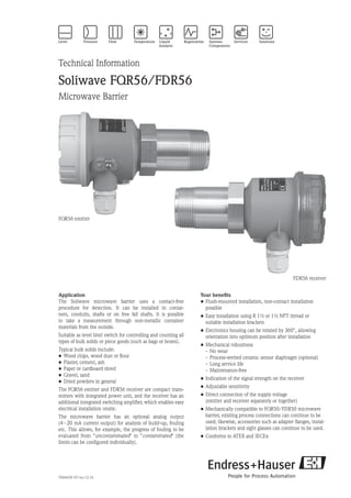
  • 1. TI00443F/97/en/12.10 Technical Information Soliwave FQR56/FDR56 Microwave Barrier Your benefits • Flush-mounted installation, non-contact installation possible • Easy installation using R 1½ or 1½ NPT thread or suitable installation brackets • Electronics housing can be rotated by 360°, allowing orientation into optimum position after installation • Mechanical robustness - No wear - Process-wetted ceramic sensor diaphragm (optional) - Long service life - Maintenance-free • Indication of the signal strength on the receiver • Adjustable sensitivity • Direct connection of the supply voltage (emitter and receiver separately or together) • Mechanically compatible to FQR50/FDR50 microwave barrier, existing process connections can continue to be used; likewise, accessories such as adapter flanges, instal- lation brackets and sight glasses can continue to be used. • Conforms to ATEX and IECEx Application The Soliwave microwave barrier uses a contact-free procedure for detection. It can be installed in contai- ners, conduits, shafts or on free fall shafts. It is possible to take a measurement through non-metallic container materials from the outside. Suitable as level limit switch for controlling and counting all types of bulk solids or piece goods (such as bags or boxes). Typical bulk solids include: • Wood chips, wood dust or flour • Plaster, cement, ash • Paper or cardboard shred • Gravel, sand • Dried powders in general The FQR56 emitter and FDR56 receiver are compact trans- mitters with integrated power unit, and the receiver has an additional integrated switching amplifier, which enables easy electrical installation onsite. The microwave barrier has an optional analog output (4 – 20 mA current output) for analysis of build-up, fouling etc. This allows, for example, the progress of fouling to be evaluated from uncontaminated to contaminated (the limits can be configured individually). FQR56 emitter FDR56 receiver
  • 2. 2 Soliwave FQR56 / FDR56 Endress+Hauser Table of contents Function and system design .................................................. 3 Measuring principle ...................................................................... 3 Characteristic quantities ....................................................... 3 Measured variable ......................................................................... 3 Measuring range (detection range) ................................................. 3 Operating frequency ...................................................................... 3 Transmission power ...................................................................... 3 Switching frequency FDR56 .......................................................... 3 Operating conditions............................................................. 4 Installation instructions ................................................................. 4 Instructions for orientation ............................................................ 4 Operation with reflector(s) ............................................................ 5 Parallel operation of multiple microwave barriers ........................... 5 Dependency of detection distance to the distance of the microwave barriers......................................................................... 6 Installation ............................................................................ 7 Direct installation with threaded connection .................................. 7 Bracket installation in front of microwave-permeable window ........ 7 Bracket installation in front of microwave-permeable window with danger of condensation on the container's inner wall ............. 7 Bracket installation in front of microwave-permeable sight glass fitting ............................................................................ 8 Angle installation on container ...................................................... 8 Flange mounting using screw-in flange .......................................... 9 Flange mounting using screw-in flange for oblique conical containers ........................................................ 9 Flange mounting using screw-in flange with danger of build-up ..... 9 Installation with pipe as wave guide ............................................. 10 Mechanical construction ...................................................... 11 Design/dimensions of F16 housing (polyester) .............................. 11 Weight ......................................................................................... 11 Material ....................................................................................... 11 Process connection ....................................................................... 11 Design/dimensions of F16 housing (stainless steel hygiene) .......... 11 Weight ......................................................................................... 11 Material ....................................................................................... 11 Process connection ....................................................................... 11 Power supply ....................................................................... 12 Electrical connection .................................................................... 12 Wiring 1: operation with one power supply .................................. 12 Wiring 2: operation with two power supplies ................................ 12 Supply voltage .............................................................................. 13 Power consumption ..................................................................... 13 Cable entry .................................................................................. 13 Cable gland .................................................................................. 13 Wire specification ......................................................................... 13 Output ................................................................................. 13 Relay ........................................................................................... 13 Solid-state relay ............................................................................ 13 Current ........................................................................................ 13 Settings ................................................................................ 14 Operating the receiver .................................................................. 14 Display ........................................................................................ 15 Parameter configuration ............................................................... 15 Configuration functions ................................................................ 16 Display on emitter ........................................................................ 17 Configuring an operating frequency .............................................. 17 Ordering information ........................................................... 18 Ordering information for FDR56 Soliwave receiver ....................... 18 Notes on product structure ........................................................... 19 Ordering information for FQR56 Soliwave emitter ........................ 20 Notes on product structure ........................................................... 20 Safety instructions ................................................................ 21 General safety instructions for electrical equipment for hazardous areas ...................................................................... 21 Zone classification ........................................................................ 21 Environment ........................................................................ 21 Ambient temperature range .......................................................... 21 Storage temperature ..................................................................... 21 Degree of protection ..................................................................... 21 Electromagnetic compatibility ....................................................... 21 Process conditions ............................................................... 21 Process temperature ..................................................................... 21 Process pressure ........................................................................... 21 Accessories .......................................................................... 22 Mounting bracket ........................................................................ 22 Installation flanges, material 316Ti (stainless steel) ........................ 22 Sight glass fitting .......................................................................... 24 High-temperature application ....................................................... 26 High-temperature adapter and extension ...................................... 26 Certificates and approvals .................................................... 27 CE approval ................................................................................. 27 Radio approval ............................................................................. 27 Ex approval .................................................................................. 27 Other standards and guidelines ..................................................... 27 Supplementary Documentation............................................. 27 Operating Instructions (KA) .......................................................... 27 Safety instructions ........................................................................ 27
  • 3. Soliwave FQR56 / FDR56 Endress+Hauser 3 Function and system design Measuring principle The FQR56 emitter puts out the microwave signal via an integrated horn antenna. The FDR56 receiver directly opposite detects this signal and generates the selected output signal (relay, solid-state relay or 4 - 20 mA current output). The range of the path is influenced by the different types of materials. The attenuation of the microwaves here depends on the electric characteristics of the attenuating material. Materials with the capacity to con- duct electricity, such as metals, reflect the waves, while other materials with lower conductivity only weaken them or are even penetrated. The attenuation of the microwaves is reduced as the dielectric constant of the material to be emitted through becomes lower. FDR56 receiverFQR56 emitter The complete measuring system for limit detection consists of an FQR56 emitter and a FDR56 receiver. Note: • The FQR56 emitter and the FDR56 receiver are compact devices for connecting to one shared power supply or two separate power supplies. • The FDR56 receiver has an integrated switching amplifier; therefore, no external switching amplifier such as the Nivotester FTR325 is required. • The FQR56/FDR56 device type remains mechanically compatible to the type FQR50/FDR50; corresponding process adapters can continue to be used. • The compact variant FQR56/FDR56 is electrically incompatible with the FQR50/FDR50 device type, as these devices have to be operated with an external switching amplifier (Nivotester FTR325). Characteristics quantities Measured variable Absorption of the electromagnetic waves radiated by the FQR56 emitter Measuring range With an unobstructed radiation path between the FQR56 emitter and the FDR56 receiver, the maximum (detection range) range is 100 m. The range also depends on the container walls to be penetrated. Operating frequency 24.15 GHz ± 80 MHz Transmission power The power produced by the FQR56 emitter is less than or equal to 100 mW e.i.r.p. (equivalent isotrope radiation performance). • Power density directly in front of the emitter: 1 mW/cm2 • Power density at a distance of 1 m: 0.3 µW/cm2 Note: The power density is clearly under the recommended limit values of the ICNIRP guidelines Guidelines for Limiting Exposure to Time-Varying Electric, Magnetic, and Electromagnetic Fields (up to 300 GHz) and thus is completely harmless for humans. Switching frequency max. 2 Hz FDR56
  • 4. 4 Soliwave FQR56 / FDR56 Endress+Hauser Operating conditions Installation instructions Both the FQR56 emitter and the FDR56 receiver are equipped with a standard thread (R 1½ to EN 10226 or 1½ NPT to ANSI/ASME B1.20.1) as the process connection. This enables easy installation in existing container couplings or nozzles. For optimal orientation of emitter and receiver after installation at the process, the electronics housing can be rotated as desired (by 360°). 2.5mm hex. • To fasten the enclosure in place, the screw (Allen screw, size 2.5) must then be tightened. • The emitter and receiver should be oppo- site and facing each other on an axis. • As the microwaves are polarized, the FQR56 emitter and the FDR56 receiver must not be turned towards each other by their longitudinal axis (except by 180° or for detection distances less than 30 cm). • Avoid interference from reflections off of metal parts. • An improvement of signal quality can be attained by installing the FQR56 emitter and FDR56 receiver so that they can be moved by ±10 mm along their longitudinal axis. • To avoid overranging when the detection range is under 30 cm, in this case, the FQR56 emitter and FDR56 receiver should be installed at a 90° angle to each other. • Between the FQR56 emitter and the FDR56 receiver, a minimum clearance of 30 mm should be maintained. Instructions for orientation 0.3 m ... 100 m 0.3 m 90°
  • 5. Soliwave FQR56 / FDR56 Endress+Hauser 5 Operation with reflector(s) If, for construction reasons, it is not possible for the FQR56 emitter and the FDR56 receiver to be directly facing each other, the microwave beam can be redirected using flat metal mirrors (reflectors). By using reflec- tors the range of the microwave barrier is reduced by approximately 10% per reflector. ReflectorReflector Reflector Note that the FQR56 emitter and FDR56 receiver have to be arranged symmetrically to the reflector (angle of entrance = angle of emission), as otherwise the receiver does not receive a signal that it can evaluate. Parallel operation of In practice, in some instances multiple microwave barriers are to be operated in parallel at one location multiple microwave barriers (e. g. for multiple limit detections in a pipe, see example). To keep the microwave barriers from influencing each other, you can operate the FQR56 emitter with three different operating frequencies. To do so, observe the following instructions: • Use the operating frequencies in series, e. g. 1, 2, 3, 1, etc. • Observe the minimum clearance A depending on the detection distance D (see diagram). • Rotate every other microwave barrier by 90° to prevent interference (see example, pertains to emitter and receiver). For details on configuring the operating frequency, refer to the section entitled Settings.
  • 6. 6 Soliwave FQR56 / FDR56 Endress+Hauser A D Dependency of detection When using microwave emitters with selectable modulation frequencies and operation as shown in the distance to the distance example for parallel operation, the following dependency of the detection distance D to the distance of the of the microwave barriers individual microwave barriers A applies. 20 40 60 80 100 120 140 160 180 200 40 30 20 10 Amin /cm D/cm Note: The values that appear in the diagram pertain to optimal installation conditions and can vary according to the installation position. When installed in closed metallic containers, hoppers or the like, in some instances reflections may occur that make it necessary to adjust the distances of the individual microwave barriers.
  • 7. Soliwave FQR56 / FDR56 Endress+Hauser 7 Installation Direct installation with R 1½ / 1½ NPT threaded connection Bracket installation in front Mounting bracket *1 of microwave-permeable window Bracket installation in front of microwave-permeable window with danger of condensation on the container's inner wall
  • 8. 8 Soliwave FQR56 / FDR56 Endress+Hauser Bracket installation in front Mounting bracket *1 Sight glass fitting *2 of microwave-permeable sight glass fitting Mounting bracket *1 Sight glass fitting *2 A*3 Purge air *6 Angle installation Mounting bracket *1 Securing arm max. 200 *4 Installation flange Ceramic disk (aluminum oxide)on container *5 *1 Suitable installation brackets are available as accessories, see Accessories *2 Suitable microwave-permeable sight glass fittings are available as accessories, see Accessories *3 The distance A depends on the nominal diameter of the sight glass fitting (or the diameter of the sight glass) and the temperature at the fitting. To prevent possible signal attenuation, we recommend keeping the distance as short as possible (e. g. max. 40 mm at DN50). *4 Distance for temperature reduction between the process temperature and max. 70°C at the microwave barrier *5 Various installation adapters (e. g. for angle installation) are available as special equipment packages. *6 We recommend using purge air to prevent fouling (material accumulation) in the nozzle that is open to the process. Alternatively, you can also close the nozzle using a plastic plug (see next page).
  • 9. Soliwave FQR56 / FDR56 Endress+Hauser 9 Flange mounting using L Plastic plug Installation flange *1 screw-in flange *1 Suitable installation flanges are available as accessories, see Accessories Note: • The maximum length L depends on the dielectric constant and the water absorption of the plastic material. Observe the manufacturer's specifications. • We recommend PTFE as the material, as this allows the length at the emitter and receiver to be up to 300 mm. • For optimal orientation, the emitter and receiver should be able to be moved by ± 10 mm along their longitudinal axis. Flange mounting using screw-in flange for oblique conical containers Flange mounting using screw-in flange with danger of build-up
  • 10. 10 Soliwave FQR56 / FDR56 Endress+Hauser Installation with L pipe as wave guide Note: • This type of mounting is recommended if conditions at the process or in the area surrounding the process are unfavorable (such as high temperatures or heavy contamination) or if the building's situation does not permit direct installation. • The pipe can be made of any desired metallic material, and the length L is unimportant due to the wave- guide effect. • Edges inside the pipe (for example at transitions) can cause signal attenuation and thus should be avoided wherever possible.
  • 11. Soliwave FQR56 / FDR56 Endress+Hauser 11 Mechanical construction Design/dimensions of F16 housing (polyester) Weight • 0.6 to 1.1 kg (depending on the version) Materials • Housing: polyester • Process connection (fluid-wetted parts): - Aluminum or stainless steel 316Ti/1.4571 - Sensor diaphragm: PTFE or ceramic • Cable glands: PA Process connection • Thread R 1½ (EN 10226) or • 1½ NPT (ANSI/ASME B1.20.1) Design/dimensions of F16 housing (stainless steel hygiene) Weight • 1.1 to 1.4 kg (depending on the version) Materials • Housing: stainless steel 316L • Process connection (fluid-wetted parts): - Stainless steel 316Ti/1.4571 - Sensor diaphragm: Ceramic or PTFE (device versions with approval) • Cable glands: - PA (device version without approval) - Brass, nickel-plated (device versions with approval) Process connection • Thread R 1½ (EN 10226) or • 1½ NPT (ANSI/ASME B1.20.1)
  • 12. 12 Soliwave FQR56 / FDR56 Endress+Hauser Power supply Electrical connection A suitable wire (see Wire specification) is used to connect the emitter and receiver of the Soliwave micro- wave barrier to one or two power supplies. The following wiring variants are permitted: Wiring 1: operation * * FQR56 emitter FDR56 receiver 1 2 1 2 1 2 3 4 5 with one power supply Signal output Power supply * * FQR56 emitter FDR56 receiver 1 2 1 2 1 2 3 4 5 Signal output Power supply Wiring 2: operation * * FQR56 emitter FDR56 receiver 1 2 1 2 1 2 3 4 5 with two power supplies Signal output Power supply 1 Power supply 2 Note: • If the emitter and receiver are to be fed by two different power supplies, these can have different voltages (versions according to the product structure). Example: Emitter supply voltage: 24 V (DC), receiver supply voltage: 230 V (AC) • For the electrical characteristics of the signal outputs, refer to the section entitled Output characteristics.
  • 13. Soliwave FQR56 / FDR56 Endress+Hauser 13 Supply voltage • AC version: 85 – 253 V (AC), 50/60 Hz • DC version: 20 – 60 V (DC) or 20 – 30 V (AC), 50/60 Hz Power consumption • FQR56: max. 2.5 VA (AC version) and max. 1 W (DC version) • FDR56: max. 4 VA (AC version) and max. 1.5 W (DC version) Cable entry • M20 x 1.5 or • ½ NPT Cable gland M20 x 1.5: • Degree of protection IP66 • Scope of supply: 2 Wire specification • Usual commercial installation wire • Conductor cross-section: max. 1.5 mm Output Relay • Potential-free change-over contact 3 4 5 • Switching capacity: - AC: 250 V/6 A - DC: 125 V/0.4 A or 30 V/5 A • Contact material: AgCdO (gold-flashed) Note: The contact material is also suitable for switching small signal circuits. However, this is possible only if no inductive loads or higher currents have been switched previously. Solid-state relay • Switching contact of a semiconductor relay 3 4 • Switching capacity: - AC: 30 V/0.4 A - DC: 40 V/0.4 A Note: Unlike the switching contact of the relay output, this can be used to evaluate higher switching frequencies (e. g. for piece goods counting). Current • Current output 4 – 20 mA A+ -4 3 • Active • Max. load: 600 Ω
  • 14. 14 Soliwave FQR56 / FDR56 Endress+Hauser Settings By using frequencies in the 24 GHz range, products with low attenuation can be detected, even if the product quantity between the emitter and receiver is low. Accordingly, the calibration options of the devices provide the necessary flexibility for adapting the barrier to the specific application without any problems: • Adjustable sensitivity • Switchable signal function: - Switch point exceeded = Max. safety (e. g. overflow protection) or - Switch point undershot = Min. safety (e. g. dry running protection) • Adjustable switching hysteresis (not with current output) • Switching delay (not with current output): - 100 ms to 20 s - with response and drop-out delay, can be selected separately • LED field strength display as an adjustment and positioning aid Operating the receiver 0F EDCBA 987 65432 1 m r q pon The Soliwave microwave barrier FQR56/FDR56 is configured using the function selection m and the two operating keys q and r. For this purpose, a calibration to a sensitivity necessary for clear and unambiguous identification of the products is carried out. If the attenuation or interruption of the microwaves by the pro- duct is sufficient, the receiver unit responds with a corresponding output signal. The parameter configuration is stored internally and is retained even after the supply voltage is disconnected. No other operator intervention is necessary during operation. The adaptation to the application is required during initial installation only. However, subsequent changes can be made and stored at any time.
  • 15. Soliwave FQR56 / FDR56 Endress+Hauser 15 Display The attenuation of the product and the configured values (in the function selection) are displayed locally using a bar graph display o. In addition, a green LED n indicates that the device is ready to operate (supply voltage is present) and a yellow LED p displays the status of the switch output (LED off: relay in rest position, solid-state relay high-impedance). Note: • Toggling the encoding switch for the function selection ( 0) puts the FDR56 receiver into parameter configuration mode. The microwave barrier continues working in the background, and changed settings are taken into account immediately. • Remember to set the function selection to 0 = operation when you are done configuring settings. • For current output, the yellow LED p has no function and remains off. Parameter configuration The parameter configuration is carried out as follows: 1. Select any desired function (for the functions that are available, refer to the section Programming functions) È Encoding switch m = 1 to F È The display shows the selected function for two seconds. Example of function 3: 2. Setting the selected function Example: function 3 (upper limit of sensitivity) È Using the r Æ and q Å keys, the upper level of sensitivity can be increased or reduced in 10% increments. or È Å È Æ È Å È Æ ... ... 3. The configured value is stored as soon as the function is switched. The value can be displayed again at any time by selecting the corresponding programming function and changed if necessary. 4. After finishing the parameter configuration (i.e. after adapting the microwave barrier to the specific applica- tion), the encoding switch must be returned to the 0 position; the barrier is now ready for operation.
  • 16. 16 Soliwave FQR56 / FDR56 Endress+Hauser Configuration functions Function/meaning Value range 1 = Automatic adjustment of the sensitivity with uncovered radiation path — 2 = Automatic adjustment of the sensitivity with covered radiation path — 3 = Manual adjustment of the sensitivity (upper limit, 10% increment/LED) È minimum (upper limit from ··· function 1) maximum 4 = Manual adjustment of the sensitivity (lower limit, 10% increment/LED) È minimum (lower limit from ··· function 1) maximum 5 = Hysteresis setting ··· 6 = Selection of the limit signal function (Min./Max. safety, relay output only) Relay switches when microwave barrier is covered Relay switches when microwave barrier is uncovered 7 = Switching delay setting (response delay) Off (no delay) 100 ms ··· (200/300/500 ms, 1/2/3/5/10 s) 20 s 8 = Switching delay setting (drop-out delay) Off (no delay) 100 ms ··· (200/300/500 ms, 1/2/3/5/10 s) 20 s 9 = Enable simulation mode Radiation path covered ··· Radiation path uncovered A = Attenuation setting Off (no attenuation) 100 ms ··· (200/300/500 ms, 1/2/3/5/10 s) 20 s F = Reset to factory settings —
  • 17. Soliwave FQR56 / FDR56 Endress+Hauser 17 Display on emitter 0F EDCBA 987 65432 1 m n The FQR56 emitter has a green LED m that signals the operating status (supply voltage present). Configuring an operating To prevent intermodulation interference from microwave barriers located close to each other, slightly different frequency operating frequencies for parallel operation (see mounting instructions in the corresponding section) can be configured: Switch position Operating frequency 0F EDCBA 987 65432 1 1 (factory setting) 0F EDCBA 987 65432 1 2 0F EDCBA 987 65432 1 3 Note: • In individual operation, the switch position is irrelevant and can be any desired position. • For additional information about settings and parameter configuration, refer to the Operating Instructions KA00291F/97
  • 18. 18 Soliwave FQR56 / FDR56 Endress+Hauser Ordering information Ordering information for 10 Approval: AA Non-hazardous areas BA ATEX II 1/2D Ex ta/tb IIIC T102°C Da/Db IP66 ATEX II 2D Ex tb IIIC T102°C Db IP66 IA IECEx Ex ta/tb IIIC T102°C Da/Db IP66 IECEx Ex tb IIIC T102°C Db IP66 99 Special version, to be specified 20 Output: 1 Relay SPDT 2 Analog 4 – 20 mA 3 Solid-state relay 9 Special version, to be specified 30 Power supply: A 85 – 253 VAC, 50/60 Hz E 20 – 60 VDC 20 – 30 VAC, 50/60 Hz Y Special version, to be specified 40 Housing: A F16 polyester, IP66 B F15 stainless steel hygiene, IP66 C F15 stainless steel hygiene, IP66 + sight glass Y Special version, to be specified 50 Electrical connection: A Gland M20 D Thread ½ NPT Y Special version, to be specified 60 Process connection: XFA Thread EN 10226 R 1½, aluminum VEA Thread ANSI 1½ NPT, aluminum XF2 Thread EN 10226 R 1½, 316Ti VE2 Thread ANSI 1½ NPT, 316Ti YYY Special version, to be specified 70 Window transmission: 1 PTFE 2 Ceramic 9 Special version, to be specified FDR56 - FDR56 Soliwave receiver
  • 19. Soliwave FQR56 / FDR56 Endress+Hauser 19 Notes on product structure For the device version FDR56-BA******, the following limitations apply: • Housing (40): (A) not permitted • Electrical connection (50): only (A) permitted • Process connection (60): (XFA) and (VEA) not permitted • Window transmission (70): only (1) permitted For the device version FDR56-IA******, the following limitations apply: • Housing (40): (A) not permitted • Process connection (60): (XFA) and (VEA) not permitted • Window transmission (70): only (1) permitted For device versions FDR56-***B*** and FDR56-***C***, the following limitations apply: • Process connection (60): (XFA) and (VEA) not permitted
  • 20. 20 Soliwave FQR56 / FDR56 Endress+Hauser Ordering information for 10 Approval: AA Non-hazardous areas BA ATEX II 1/2D Ex ta/tb IIIC T102°C Da/Db IP66 ATEX II 2D Ex tb IIIC T102°C Db IP66 IA IECEx Ex ta/tb IIIC T102°C Da/Db IP66 IECEx Ex tb IIIC T102°C Db IP66 99 Special version, to be specified 20 Power supply: A 85 – 253 VAC, 50/60 Hz E 20 – 60 VDC 20 – 30 VAC, 50/60 Hz Y Special version, to be specified 30 Housing: A F16 polyester, IP66 B F15 stainless steel hygiene, IP66 Y Special version, to be specified 40 Electrical connection: A Gland M20 D Thread ½ NPT Y Special version, to be specified 50 Process connection: XFA Thread EN 10226 R 1½, aluminum VEA Thread ANSI 1½ NPT, aluminum XF2 Thread EN 10226 R 1½, 316Ti VE2 Thread ANSI 1½ NPT, 316Ti YYY Special version, to be specified 60 Window transmission: 1 PTFE 2 Ceramic 9 Special version, to be specified FQR56 - FQR56 Soliwave emitter Notes on product structure For the device version FQR56-BA***** the following limitations apply: • Housing (30): (A) not permitted • Electrical connection (40): only (A) permitted • Process connection (50): (XFA) and (VEA) not permitted • Window transmission (60): only (1) permitted For the device version FQR56-IA*****, the following limitations apply: • Housing (30): (A) not permitted • Process connection (50): (XFA) and (VEA) not permitted • Window transmission (60): only (1) permitted For the device version FQR56-**B***, the following limitations apply: • Process connection (50): (XFA) and (VEA) not permitted
  • 21. Soliwave FQR56 / FDR56 Endress+Hauser 21 Safety instructions General safety instructions • Install it according to manufacturer's specifications and the standards and regulations applicable in your for electrical equipment area. for hazardous areas • Installation, electrical connection, commissioning, operation and, if necessary, maintenance may be carried out only by trained specialists authorized to do so by the facility's owner-operator. • Do not operate the devices of the microwave barrier outside of the electrical, thermal or mechanical cha- racteristic quantities. • For additional safety instructions, refer to the XA00509F/97/a3 (ATEX) or XA00543F/97/en (IECEx) Zone classification Hazardous areas Emitter FQR56-BA* FQR56-IA* Receiver FDR56-BA* FDR56-IA* Zone 20 Zone 21 Environment Ambient temperature • -40°C to +70°C Storage temperature • -40°C to +80°C Degree of protection • With closed housing: IP 66 • With open housing: IP 20 Electromagnetic compatibility • Interference Emission to EN 61326, Electrical Equipment Class B (EMC) • Interference Immunity to EN 61326, Appendix A (Industrial) Process conditions Process temperature • -40°C to +70°C (without optional adapter for temperature reduction) • -40°C to +450°C (with optional adapter for temperature reduction, see Accessories) Process pressure • 50 to 680 kPa absolute (0.5 to 6.8 bar absolute) (Applies only when FQR56 emitter or FDR56 receiver is installed directly in the process.) • 80 to 510 kPa absolute (0.8 to 5.1 bar absolute) (Applies only when using the optional adapter for temperature reduction.)
  • 22. 22 Soliwave FQR56 / FDR56 Endress+Hauser Accessories Mounting bracket The FQR56 emitter and FDR56 receiver can be easily installed on existing frames using a mounting bracket. Mounting bracket for frame mounting • Aluminum material: Part number 52017501 • Plastic material: Part number 52017502 M6 / ¼ UNC 86 66 66 66 Installation flanges, material: 316Ti (stainless steel) Connection dimensions to DIN EN 1092-1, with Rp 1½ internal thread: • DN40 PN16 Part number 71006348 with inspection certificate to EN 10204-3.1 Part number 71108383 • DN50 PN16 Part number 71006350 with inspection certificate to EN 10204-3.1 Part number 71108388 • DN100 PN16 Part number 71006352 with inspection certificate to EN 10204-3.1 Part number 71108390
  • 23. Soliwave FQR56 / FDR56 Endress+Hauser 23 d3 Rp1½ d2 d1 D Flange d1/ mm d2/ mm d3/ mm D/ mm Number of bores DN40/PN16 110 150 18 16 4 DN50/PN16 125 165 18 18 4 DN100/PN16 180 220 18 20 8 Connection dimensions to ANSI/ASME B16.5, with 1½ NPT internal thread: • 1½ 150 lbs Part number 71006349 with inspection certificate to EN 10204-3.1 Part number 71108387 • 2 150 lbs Part number 71006351 with inspection certificate to EN 10204-3.1 Part number 71108389 • 4 150 lbs Part number 71006353 with inspection certificate to EN 10204-3.1 Part number 71108391 d3 1½NPT Flange d1/ mm d2/ mm d3/ mm D/ mm Number of bores 1½ 150 lbs 98.6 127 15.7 17.5 4 2 150 lbs 120.7 152.4 19.1 19.1 4 4 150 lbs 190.5 228.6 19.1 23.9 8 d1 d2 D
  • 24. 24 Soliwave FQR56 / FDR56 Endress+Hauser Sight glass fitting Screw-type fitting similar to DIN 11851, materials: stainless steel 304, silicone and C4400, Pmax = 600 kPa (6 bar), Tmax = 200°C, borosilicate glass, screw-on installation, thread adapter nut d2 D A DN d1/ mm d2/ mm s/ mm D/ mm d/ mm A/ mm a/ mm 50 50 63 10 92 61 44 21 80 80 94 12 127 93 57 25 100 100 113 15 148 114 69 34 d1 DN d sa • DN 50, part number 71026440 • DN 80, part number 71026441 • DN 100, part number 71026442 Weld-in fitting for unpressurized containers, materials: stainless steel 316Ti and silicone, Tmax = 200°C, borosilicate glass, screw-on installation DN d1/ mm d2/ mm D/ mm k/ mm d3/ mm 50 80 100 140 120 102 80 100 125 165 145 127 100 125 150 190 170 152 d2 d3 d1 k D 10 15 • DN 50, part number 71026443 • DN 80, part number 71026444 • DN 100, part number 71026445
  • 25. Soliwave FQR56 / FDR56 Endress+Hauser 25 Weld-in fitting to DIN 28120, materials: stainless steel 316Ti/321 and silicone, Pmax = 1 MPa (10 bar), Tmax = 200°C, borosilicate glass, screw-on installation k D DN d1/ mm d2/ mm D/ mm k/ mm h1/ mm d3/ mm 50 80 100 165 125 16 102 80 100 125 200 160 20 127 100 125 150 220 180 22 152 d1 d2 d3 h130 45° • DN 50, part number 71026446 • DN 80, part number 71026447 • DN 100, part number 71026448 Flange fitting to DIN 28121 for screwing onto existing counterflanges, materials: stainless steel 316Ti, PTFE and C4400, Pmax = 2.5 MPa (25 bar), Tmax = 200°C, borosilicate glass d10 DN d1/ mm d3/ mm s/ mm D/ mm k/ mm h3/ mm d9/ mm d10/ mm 50 65 80 15 165 125 41 18 82 80 80 100 20 200 160 50 18 102 100 100 125 25 235 190 59 22 127 h3 7 d3 d1 d9 k D d1 d10 Seal, product-side s • DN 50, part number 71026449 • DN 80, part number 71026450 • DN 100, part number 71026451
  • 26. 26 Soliwave FQR56 / FDR56 Endress+Hauser High-temperature application For applications with process temperatures up to +450°C, the temperature reduction to max. +70°C takes place on the microwave barrier with a corresponding high-temperature adapter (with extension where necessary). The length of the adapter is based on the insulation thickness to be penetrated (if present) and the ambient conditions at the measuring point. Tmax = +70°CTP,max = +450°C Pmax = 80 ... 510 kPa abs. (0.8 ... 5.1 bar abs.) Wall Insulation HT adapter Extension X Note: • To maintain the maximum temperature of +70°C at the FQR56/FDR56, we recommend a minimum difference (X) of 200 mm between the process or the insulation and the devices. • The individual extensions can also be combined in any way desired. • Each high-temperature adapter results in a reduction of the range. High-temperature adapter R1½/1½NPT 170 L m n and extension HT adapter m with flush-mounted ceramic disk: • Thread R 1½ or Rp 1½, 55mm hex, 316Ti/1.4571 Part number 71113441 • Thread 1½ NPT, 55mm hex, 316Ti/1.4571 Part number 71113449 Extension for HT adapter n: • Thread R 1½ or Rp 1½, 55mm hex, 316Ti/1.4571 L = 225 mm Part number 71113450 L = 325 mm Part number 71113451 L = 525 mm Part number 71113452 • Thread 1½ NPT, 55mm hex, 316Ti/1.4571 L = 225 mm Part number 71113453 L = 325 mm Part number 71113454 L = 525 mm Part number 71113455
  • 27. Soliwave FQR56 / FDR56 Endress+Hauser 27 Certificates and approvals CE mark The Soliwave microwave barrier is in conformity with the statutory requirements of the EC Directives. The manufacturer confirms successful testing of the device by affixing to it the CE mark. Radio approval RTTE to EN 300440-2 Ex approval ATEX II 1/2D or IECEx Other standards Directive 1999/05/EC Article 3.1 (a) and 3.1 (b) and the included Directives 73/23/EEC and 89/336/EEC and guidelines Supplementary Documentation Operating Instructions (KA) Soliwave FQR56/FDR56 KA00291F/97/a6 Safety instructions Soliwave FQR56/FDR56-BA* XA00509F/97/a3 Soliwave FQR56/FDR56-IA* XA00543F/97/en
  • 28. 28 Soliwave FQR56 / FDR56 Endress+Hauser International Head Quarter Endress+Hauser GmbH+Co. KG Instruments International Colmarer Str. 6 79576 Weil am Rhein Deutschland Tel. +49 76 21 9 75 02 Fax +49 76 21 9 75 34 5 www.endress.com info@ii.endress.com TI00443F/97/en/12.10 InDesign 6.0.6 Subject to modifications and amendments