Descargar como PDF, PPTX
![import processing.serial.*;
Serial port; String buff = "";
int NEWLINE = 10; // Store the last 64 values received so
we can graph them.
int[] values = new int[64];
void setup() { size(512, 256);
println("Available serial ports:");
println(Serial.list());
port = new Serial(this, Serial.list()[0], 9600);
// If you know the name of the port used by the Arduino
board, you
// can specify it directly like this.
//port = new Serial(this, "COM1", 9600); }
void draw() { background(53); stroke(255);
for (int i = 0; i < 63; i++)
line(i * 8, 255 - values[i], (i + 1) * 8, 255 - values[i +
1]);](https://image.slidesharecdn.com/tutorialarduino03-programacin-110519235747-phpapp01/85/Tutorial-arduino-03-programacion-21-320.jpg)
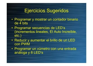
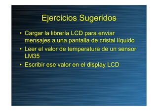
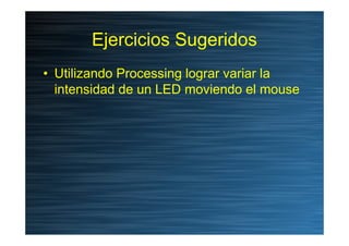

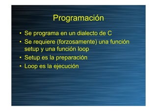
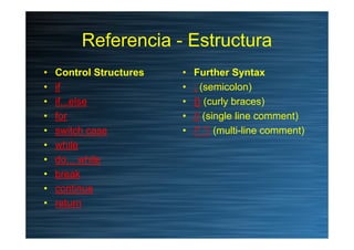
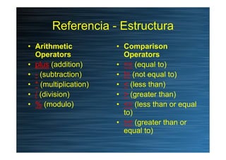
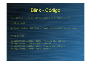
Este documento presenta una introducción a la programación de Arduino. Explica que el Arduino se programa en un dialecto de C y requiere funciones setup y loop. También describe estructuras de control como if/else, bucles for y while, operadores aritméticos y de comparación, y funciones digitales, analógicas y de tiempo. Finalmente, presenta ejemplos de código y sugiere ejercicios prácticos.


