SlideShare una empresa de Scribd logo
1 de 15
Descargar para leer sin conexión
Bus Rollover Simulation & AnalysisShare
Bus Rollover- Introduction
Bus rollover event is one of the most crucial hazards for the safety of passengers and the crew riding in a
bus. In the past few years it has been observed that after rollover accidents the deforming body structure
seriously threatens the lives of the passengers. Hence, rollover strength of the bus bodies has become an
important issue for bus and coach manufacturers.
In India, the general trend noticed in the market is that OEMs sell their drive away bus chassis. The bus
body design and building is done by third party bus body builders. Many bus body builders unknowingly
employ poor designs, resulting in large amounts of fatal accidents, mostly rollover. The existing bus body
structures are inadequately designed, sub-optimal and unsafe. Wood is used in the construction of the bus
bodies to a large extent.
The cause for death or injury in bus roll over is primarily due to intrusion of structure inside the
passenger’s survival space. Hence, the bus body (superstructure) should be strong enough to absorb the
energy of impact caused by bus rollover and the resulting deformation of the superstructure should not
result in intruding the minimum survival space for the passengers.
Fig.1 Bus Rollover
The government bodies have regulated the bus rollover strength requirements of the bus bodies by
releasing Automotive Standards like AIS-052 & AIS-031. These regulations ensure that the bus body
superstructure is strong and safe in an event of a rollover accident.
Types of Bus Rollover Accidents
Mainly there are 2 possible cases of bus rollover accidents.
Fig.2 Bus Rollover Cases
The case that needs to be considered for compliance mainly depends on the usability of the vehicle. A city
bus has to run on good quality roads and the possibility of roll over is only during high speed cornering
(E.g. BRTS Corridor), so Case-2 (bus rolls over on ground) will be selected. On the other hand if it is an
intercity/tourist bus, the probability of roll over into a ditch is high, Hence Case-1 (bus rolls over into a
ditch of 800 mm depth) is selected.
However, the structural strength requirement is mostly driven by AIS-031. AIS 031 standard ensures that
the bus body superstructure has sufficient strength such that no part of the structure intrudes into the
residual space (explained below) of passenger in the event of rollover.
Physics behind Bus Rollover
Bus rollover is a phenomenon in which the fully laden bus rolls about an axis parallel to the longitudinal
direction of the bus passing through the outermost edge of the outermost tyre (Right/Left/Front/Rear) on
ground.
Bus rollover happens due to collision or high speed during cornering. As a vehicle rounds a corner, three
forces act on it: tire forces (the centripetal force), inertial effects (the centrifugal force), and gravity. The
cornering forces from the tire push the vehicle towards the center of the curve. This force acts at ground
level, below the center of mass. The force of inertia acts horizontally through the vehicle's center of mass
away from the center of the turn. These two forces make the vehicle roll towards the outside of the curve.
The force of the vehicle's weight acts downward through the center of mass in the opposite direction.
When the tire and inertial forces are enough to overcome the force of gravity, the vehicle starts to turn
over.
Methods for Bus Rollover Analysis
Physical Testing
During physical testing, the bus placed on platform is tilted about the rotation point (specified as per AIS-
031) with the angular velocity of not more than 0.087 rads/sec. At some specific angle, the bus C.G.
imbalances and the bus rolls into the ditch of depth 800 mm due to its own gravity. The intrusion of the
side structure into the residual space is checked manually and regulation pass/fail is decided based on the
AIS-031 criteria.
Computer Aided Engineering - Bus Rollover Simulation
In this method the actual case is simulated to an extent that is accurate enough to confirm the protection
from rollover. It is a cost effective & less time consuming process. Moreover, bus rollover simulation in
comparison to physical testing provides enough scope for optimizing the bus body structure which further
helps in reducing the overall weight of the bus.
Conventionally many bus body builders go for actual vehicle’s physical testing which incurs huge cost
and time. It is advisable to achieve the same result with bus rollover simulation. The method is explained
in brief below.
For bus rollover simulation we require final angular velocity of the bus during impact on ground & the
residual space as per AIS-031 definition.
Residual Space Creation
Fig.3 Residual space
1. Residual Space (Survival Space) is to be created in the bus as per AIS-031 shown in Fig.3.
2. The position of the "R" point shown in Fig.3 shall be assumed to be 500 mm above the floor under the
passenger’s feet, 300 mm from the inner surface of the side of the vehicle and 100 mm in front of the
seat back in the Centre-Line of the outboard seats.
3. Height of the Residual space should be minimum 750 mm.
Bus Rollover Kinematics
It explains the position of rotation points about which bus rolls and calculation of angular velocity with
which bus rolls into the ditch.
Fig.4 Bus Rollover Kinematics
1. First Rotation (θ1, Position A to B): The bus along with stoppers should be rotated about the bottom
point of rear wheel stopper (O1) till the CoG of bus reaches maximum height (Unstable position).
2. Second Rotation (θ2, Position B to C): The bus excluding stoppers should be rotated about the top most
point (O2) of the rear stopper (Point height=80 mm) till it touches impact floor. (Note: Keep 1-1.5 mm
gap between Impact floor and part which comes first in contact)
 Angular velocity is calculated by using formula: (Refer Fig.5)
1/2 IRA ω2
= M * g * ∆H
Where,
IRA = ICOG_XX + Mass * D2
(Mass moment of inertia about rotational axis)
∆H = Height between Max. CoG & Final CoG
D = Distance between CoG and Second point of rotation O2
ω= Angular Velocity
M = Total mass of the bus
g = Acceleration due to gravity
CAE- Bus Rollover Simulation
Bus rollover simulation can be performed in several ways (1D/2D/3D mesh) & using various softwares,
but the most appropriate method & softwares are considered in terms of accuracy and speed of solution.
The CAE simulation includes four major steps, viz. CAD Preparation, Rollover Kinematics, Residual
Space, Deck Pre-processing, Deck Solving and Post-processing as described below.
Deck Pre-processing
1. Accurate finite element 2D mesh model is prepared from the CAD model of the bus super structure &
chassis.
2. Connections i.e. welding and bolts are modelled using 1-D elements.
3. All components mounted on the structure are either meshed or used as lumped mass (0D Mesh).
4. The overall weight & CoG of the bus is matched with the actual bus.
5. Assignment of Material properties.
6. Application of Gravity load at global CoG of bus and Angular velocity to all components of bus.
7. Assignment of Termination time, Time step required for simulation and output files needed for post
processing.
Solution
 The Deck prepared should be imported in solver and number of CPU’s required for run should be
mentioned.
 Check for any errors; make corrections as per error and Rerun the analysis.
 Check for mass addition and percentage increase mass.
 Run the Solution, this generally takes 24 Hours to solve the mathematical model.
Post-processing
 Check energy balance i.e. Total Energy, Internal Energy, Kinetic Energy, Rigid Wall energy and
Sliding Interface Energy of each component of bus.
Fig.5 Energy balance
 Gap Measurement:
Fig.6 Gap measurement between residual space and pillars
 If gap is more than 5 mm, then the structure is not penetrating into the residual spaces and it passes
AIS-031.
 If gap is less than 5 mm, then the structure fails and suitable countermeasures need be taken.
Factors Affecting Bus Rollover Performance
Position of Centre of Gravity (CoG)
Stability of bus while turning is dependent on the position of CoG of bus. If height of bus CoG is more,
the bus will be more prone to rollover than one having low CoG. Also as height of CoG increases, the
radius of rotation will increase, which increases the kinetic energy in structure before impact resulting
more damage to superstructure.
Fig.7 Position of CoG
Hence, during design proper caution should be taken to ensure minimum CoG of the Bus.
Number and Position of Pillars
As the structural pillars absorb energy during roll over impact, it is necessary to optimise the no of pillars.
More no of pillars will add unnecessary weight and less no of pillars will fail in rollover simulation.
Tubes Cross Section
The strength of the structure is mostly depending on the cross section of the tubes used in the structure. If
the bus is failing in rollover analysis, the strength of the structure can be increased by increasing cross
section (Breadth, width or thickness) of crucial members in rollover analysis.
Material Properties
The stronger the material, the stronger the bus is against rollover. Material should absorb more energy of
impact by deforming rather than failing. Aluminium can be used for stretch panels which weighs less and
absorbs more energy.
Reinforcement Optimization
Fig.8 Failure Bus Rollover Simulation &
Analysis
Share
Bus Rollover- Introduction
Bus rollover event is one of the most crucial hazards for the safety of passengers and the crew riding in a
bus. In the past few years it has been observed that after rollover accidents the deforming body structure
seriously threatens the lives of the passengers. Hence, rollover strength of the bus bodies has become an
important issue for bus and coach manufacturers.
In India, the general trend noticed in the market is that OEMs sell their drive away bus chassis. The bus
body design and building is done by third party bus body builders. Many bus body builders unknowingly
employ poor designs, resulting in large amounts of fatal accidents, mostly rollover. The existing bus body
structures are inadequately designed, sub-optimal and unsafe. Wood is used in the construction of the bus
bodies to a large extent.
The cause for death or injury in bus roll over is primarily due to intrusion of structure inside the
passenger’s survival space. Hence, the bus body (superstructure) should be strong enough to absorb the
energy of impact caused by bus rollover and the resulting deformation of the superstructure should not
result in intruding the minimum survival space for the passengers.
Fig.1 Bus Rollover
The government bodies have regulated the bus rollover strength requirements of the bus bodies by
releasing Automotive Standards like AIS-052 & AIS-031. These regulations ensure that the bus body
superstructure is strong and safe in an event of a rollover accident.
Types of Bus Rollover Accidents
Mainly there are 2 possible cases of bus rollover accidents.
Fig.2 Bus Rollover Cases
The case that needs to be considered for compliance mainly depends on the usability of the vehicle. A city
bus has to run on good quality roads and the possibility of roll over is only during high speed cornering
(E.g. BRTS Corridor), so Case-2 (bus rolls over on ground) will be selected. On the other hand if it is an
intercity/tourist bus, the probability of roll over into a ditch is high, Hence Case-1 (bus rolls over into a
ditch of 800 mm depth) is selected.
However, the structural strength requirement is mostly driven by AIS-031. AIS 031 standard ensures that
the bus body superstructure has sufficient strength such that no part of the structure intrudes into the
residual space (explained below) of passenger in the event of rollover.
Physics behind Bus Rollover
Bus rollover is a phenomenon in which the fully laden bus rolls about an axis parallel to the longitudinal
direction of the bus passing through the outermost edge of the outermost tyre (Right/Left/Front/Rear) on
ground.
Bus rollover happens due to collision or high speed during cornering. As a vehicle rounds a corner, three
forces act on it: tire forces (the centripetal force), inertial effects (the centrifugal force), and gravity. The
cornering forces from the tire push the vehicle towards the center of the curve. This force acts at ground
level, below the center of mass. The force of inertia acts horizontally through the vehicle's center of mass
away from the center of the turn. These two forces make the vehicle roll towards the outside of the curve.
The force of the vehicle's weight acts downward through the center of mass in the opposite direction.
When the tire and inertial forces are enough to overcome the force of gravity, the vehicle starts to turn
over.
Methods for Bus Rollover Analysis
Physical Testing
During physical testing, the bus placed on platform is tilted about the rotation point (specified as per AIS-
031) with the angular velocity of not more than 0.087 rads/sec. At some specific angle, the bus C.G.
imbalances and the bus rolls into the ditch of depth 800 mm due to its own gravity. The intrusion of the
side structure into the residual space is checked manually and regulation pass/fail is decided based on the
AIS-031 criteria.
Computer Aided Engineering - Bus Rollover Simulation
In this method the actual case is simulated to an extent that is accurate enough to confirm the protection
from rollover. It is a cost effective & less time consuming process. Moreover, bus rollover simulation in
comparison to physical testing provides enough scope for optimizing the bus body structure which further
helps in reducing the overall weight of the bus.
Conventionally many bus body builders go for actual vehicle’s physical testing which incurs huge cost
and time. It is advisable to achieve the same result with bus rollover simulation. The method is explained
in brief below.
For bus rollover simulation we require final angular velocity of the bus during impact on ground & the
residual space as per AIS-031 definition.
Residual Space Creation
Fig.3 Residual space
1. Residual Space (Survival Space) is to be created in the bus as per AIS-031 shown in Fig.3.
2. The position of the "R" point shown in Fig.3 shall be assumed to be 500 mm above the floor under
the passenger’s feet, 300 mm from the inner surface of the side of the vehicle and 100 mm in front
of the seat back in the Centre-Line of the outboard seats.
3. Height of the Residual space should be minimum 750 mm.
Bus Rollover Kinematics
It explains the position of rotation points about which bus rolls and calculation of angular velocity with
which bus rolls into the ditch.
Fig.4 Bus Rollover Kinematics
1. First Rotation (θ1, Position A to B): The bus along with stoppers should be rotated about the
bottom point of rear wheel stopper (O1) till the CoG of bus reaches maximum height (Unstable
position).
2. Second Rotation (θ2, Position B to C): The bus excluding stoppers should be rotated about the top
most point (O2) of the rear stopper (Point height=80 mm) till it touches impact floor. (Note: Keep
1-1.5 mm gap between Impact floor and part which comes first in contact)
 Angular velocity is calculated by using formula: (Refer Fig.5)
1/2 IRA ω2
= M * g * ∆H
Where,
IRA = ICOG_XX + Mass * D2
(Mass moment of inertia about rotational axis)
∆H = Height between Max. CoG & Final CoG
D = Distance between CoG and Second point of rotation O2
ω= Angular Velocity
M = Total mass of the bus
g = Acceleration due to gravity
CAE- Bus Rollover Simulation
Bus rollover simulation can be performed in several ways (1D/2D/3D mesh) & using various softwares,
but the most appropriate method & softwares are considered in terms of accuracy and speed of solution.
The CAE simulation includes four major steps, viz. CAD Preparation, Rollover Kinematics, Residual
Space, Deck Pre-processing, Deck Solving and Post-processing as described below.
Deck Pre-processing
1. Accurate finite element 2D mesh model is prepared from the CAD model of the bus super
structure & chassis.
2. Connections i.e. welding and bolts are modelled using 1-D elements.
3. All components mounted on the structure are either meshed or used as lumped mass (0D Mesh).
4. The overall weight & CoG of the bus is matched with the actual bus.
5. Assignment of Material properties.
6. Application of Gravity load at global CoG of bus and Angular velocity to all components of bus.
7. Assignment of Termination time, Time step required for simulation and output files needed for
post processing.
Solution
 The Deck prepared should be imported in solver and number of CPU’s required for run should be
mentioned.
 Check for any errors; make corrections as per error and Rerun the analysis.
 Check for mass addition and percentage increase mass.
 Run the Solution, this generally takes 24 Hours to solve the mathematical model.
Post-processing
 Check energy balance i.e. Total Energy, Internal Energy, Kinetic Energy, Rigid Wall energy and
Sliding Interface Energy of each component of bus.
Fig.5 Energy balance
 Gap Measurement:
Fig.6 Gap measurement between residual space and pillars
 If gap is more than 5 mm, then the structure is not penetrating into the residual spaces and it
passes AIS-031.
 If gap is less than 5 mm, then the structure fails and suitable countermeasures need be taken.
Factors Affecting Bus Rollover Performance
Position of Centre of Gravity (CoG)
Stability of bus while turning is dependent on the position of CoG of bus. If height of bus CoG is more,
the bus will be more prone to rollover than one having low CoG. Also as height of CoG increases, the
radius of rotation will increase, which increases the kinetic energy in structure before impact resulting
more damage to superstructure.
Fig.7 Position of CoG
Hence, during design proper caution should be taken to ensure minimum CoG of the Bus.
Number and Position of Pillars
As the structural pillars absorb energy during roll over impact, it is necessary to optimise the no of pillars.
More no of pillars will add unnecessary weight and less no of pillars will fail in rollover simulation.
Tubes Cross Section
The strength of the structure is mostly depending on the cross section of the tubes used in the structure. If
the bus is failing in rollover analysis, the strength of the structure can be increased by increasing cross
section (Breadth, width or thickness) of crucial members in rollover analysis.
Material Properties
The stronger the material, the stronger the bus is against rollover. Material should absorb more energy of
impact by deforming rather than failing. Aluminium can be used for stretch panels which weighs less and
absorbs more energy.
Reinforcement Optimization
Fig.8 Failure locations
As shown in the fig.9, the superstructure fails at the shown junction points. To avoid that we can increase
the tube's cross-section, but that will increase the overall weight of the bus.
Hence, it is advised to provide local stiffeners, it adds less weight and increases the strength of the bus
against rollover.
-
Rushikesh Savant
Advanced Structures India Pvt Ltd is an independent automotive product development company based out
of Bangalore, India with operations in India, China and US. Above is a blog entry from our engineers
about Bus Rollover. We can be contacted on business@advancedstructures.in for business enquiries and
careers@advancedstructures.in for open positions
locations
As shown in the fig.9, the superstructure fails at the shown junction points. To avoid that we can increase
the tube's cross-section, but that will increase the overall weight of the bus.
Hence, it is advised to provide local stiffeners, it adds less weight and increases the strength of the bus
against rollover.
-
Rushikesh Savant
Advanced Structures India Pvt Ltd is an independent automotive product development company based out
of Bangalore, India with operations in India, China and US. Above is a blog entry from our engineers
about Bus Rollover. We can be contacted on business@advancedstructures.in for business enquiries and
careers@advancedstructures.in for open positions

Más contenido relacionado

La actualidad más candente

Automotive Circle Conference: bmw insight edition 2016 - Constellium presenta...
Automotive Circle Conference: bmw insight edition 2016 - Constellium presenta...Automotive Circle Conference: bmw insight edition 2016 - Constellium presenta...
Automotive Circle Conference: bmw insight edition 2016 - Constellium presenta...Constellium
 
Optimization based Chassis Design
Optimization based Chassis DesignOptimization based Chassis Design
Optimization based Chassis DesignAltair
 
FEA Project 1- Akash Marakani
FEA Project 1- Akash MarakaniFEA Project 1- Akash Marakani
FEA Project 1- Akash MarakaniAkash Marakani
 
Crash Timestep Basics
Crash Timestep BasicsCrash Timestep Basics
Crash Timestep BasicsSATISHGOMBI
 
Setting up a crash simulation in LS-Dyna
Setting up a crash simulation in LS-DynaSetting up a crash simulation in LS-Dyna
Setting up a crash simulation in LS-DynaAkshay Mistri
 
Assessing the torsional stiffness of a simplified ladder frame chassis
Assessing the torsional stiffness of a simplified ladder frame chassisAssessing the torsional stiffness of a simplified ladder frame chassis
Assessing the torsional stiffness of a simplified ladder frame chassissaeid ghaffari
 
Future trends in automobile engineering
Future trends in automobile engineeringFuture trends in automobile engineering
Future trends in automobile engineeringUmama S
 
Vehicle Body Terminology, Visibility & Space
Vehicle Body  Terminology, Visibility & SpaceVehicle Body  Terminology, Visibility & Space
Vehicle Body Terminology, Visibility & SpaceRajat Seth
 
Car crash protection
Car crash protection  Car crash protection
Car crash protection Suyash Rewale
 
Chassis operating conditions
Chassis operating conditionsChassis operating conditions
Chassis operating conditionsAnanda Murugan M
 
Quarter model of passive suspension system with simscape
Quarter model of passive suspension system with simscapeQuarter model of passive suspension system with simscape
Quarter model of passive suspension system with simscapeabuamo
 
Vehicle Body Engineering Bus Body Details
Vehicle Body Engineering Bus Body DetailsVehicle Body Engineering Bus Body Details
Vehicle Body Engineering Bus Body DetailsRajat Seth
 
Roof crush test using LS-DYNA
Roof crush test using LS-DYNARoof crush test using LS-DYNA
Roof crush test using LS-DYNASuravi Banik
 
Vehicle Design construction
Vehicle Design constructionVehicle Design construction
Vehicle Design constructionRajat Seth
 
FEA methodology for Composites in Ls-Dyna
FEA methodology for Composites in Ls-DynaFEA methodology for Composites in Ls-Dyna
FEA methodology for Composites in Ls-DynaTamilselvan Murugan
 
Finite Element Analysis of Fire Truck Chassis for Steel and Carbon Fiber Mate...
Finite Element Analysis of Fire Truck Chassis for Steel and Carbon Fiber Mate...Finite Element Analysis of Fire Truck Chassis for Steel and Carbon Fiber Mate...
Finite Element Analysis of Fire Truck Chassis for Steel and Carbon Fiber Mate...IJERA Editor
 

La actualidad más candente (20)

Automotive Circle Conference: bmw insight edition 2016 - Constellium presenta...
Automotive Circle Conference: bmw insight edition 2016 - Constellium presenta...Automotive Circle Conference: bmw insight edition 2016 - Constellium presenta...
Automotive Circle Conference: bmw insight edition 2016 - Constellium presenta...
 
Optimization based Chassis Design
Optimization based Chassis DesignOptimization based Chassis Design
Optimization based Chassis Design
 
FEA Project 1- Akash Marakani
FEA Project 1- Akash MarakaniFEA Project 1- Akash Marakani
FEA Project 1- Akash Marakani
 
Biw with definitions
Biw with definitionsBiw with definitions
Biw with definitions
 
Crash Timestep Basics
Crash Timestep BasicsCrash Timestep Basics
Crash Timestep Basics
 
FEA Analysis - Thin Plate
FEA Analysis - Thin PlateFEA Analysis - Thin Plate
FEA Analysis - Thin Plate
 
Setting up a crash simulation in LS-Dyna
Setting up a crash simulation in LS-DynaSetting up a crash simulation in LS-Dyna
Setting up a crash simulation in LS-Dyna
 
Assessing the torsional stiffness of a simplified ladder frame chassis
Assessing the torsional stiffness of a simplified ladder frame chassisAssessing the torsional stiffness of a simplified ladder frame chassis
Assessing the torsional stiffness of a simplified ladder frame chassis
 
Future trends in automobile engineering
Future trends in automobile engineeringFuture trends in automobile engineering
Future trends in automobile engineering
 
Vehicle Body Terminology, Visibility & Space
Vehicle Body  Terminology, Visibility & SpaceVehicle Body  Terminology, Visibility & Space
Vehicle Body Terminology, Visibility & Space
 
Car crash protection
Car crash protection  Car crash protection
Car crash protection
 
ACE Seats Crash Test 2015
ACE Seats Crash Test 2015ACE Seats Crash Test 2015
ACE Seats Crash Test 2015
 
Chassis operating conditions
Chassis operating conditionsChassis operating conditions
Chassis operating conditions
 
Quarter model of passive suspension system with simscape
Quarter model of passive suspension system with simscapeQuarter model of passive suspension system with simscape
Quarter model of passive suspension system with simscape
 
Vehicle Body Engineering Bus Body Details
Vehicle Body Engineering Bus Body DetailsVehicle Body Engineering Bus Body Details
Vehicle Body Engineering Bus Body Details
 
Roof crush test using LS-DYNA
Roof crush test using LS-DYNARoof crush test using LS-DYNA
Roof crush test using LS-DYNA
 
Analysis of chassis
Analysis of chassisAnalysis of chassis
Analysis of chassis
 
Vehicle Design construction
Vehicle Design constructionVehicle Design construction
Vehicle Design construction
 
FEA methodology for Composites in Ls-Dyna
FEA methodology for Composites in Ls-DynaFEA methodology for Composites in Ls-Dyna
FEA methodology for Composites in Ls-Dyna
 
Finite Element Analysis of Fire Truck Chassis for Steel and Carbon Fiber Mate...
Finite Element Analysis of Fire Truck Chassis for Steel and Carbon Fiber Mate...Finite Element Analysis of Fire Truck Chassis for Steel and Carbon Fiber Mate...
Finite Element Analysis of Fire Truck Chassis for Steel and Carbon Fiber Mate...
 

Similar a 64 bus rollover simulation

Design and finite element analysis of under frame arrangement (universal head...
Design and finite element analysis of under frame arrangement (universal head...Design and finite element analysis of under frame arrangement (universal head...
Design and finite element analysis of under frame arrangement (universal head...eSAT Journals
 
Design and analysis of state transport (s.t) utility vehicle ~ bus ijvss 2019
Design and analysis of state transport (s.t) utility vehicle ~ bus ijvss 2019Design and analysis of state transport (s.t) utility vehicle ~ bus ijvss 2019
Design and analysis of state transport (s.t) utility vehicle ~ bus ijvss 2019Dr.Vikas Deulgaonkar
 
Study of Different Parameters on the Chassis Space Frame For the Sports Car b...
Study of Different Parameters on the Chassis Space Frame For the Sports Car b...Study of Different Parameters on the Chassis Space Frame For the Sports Car b...
Study of Different Parameters on the Chassis Space Frame For the Sports Car b...IOSR Journals
 
Stress Analysis of a heavy duty vehicle chassis by using FEA
Stress Analysis of a heavy duty vehicle chassis by using FEAStress Analysis of a heavy duty vehicle chassis by using FEA
Stress Analysis of a heavy duty vehicle chassis by using FEADigitech Rathod
 
IRJET- Strength Evaluation of Tipper Chassis under Static and Dynamic Load Co...
IRJET- Strength Evaluation of Tipper Chassis under Static and Dynamic Load Co...IRJET- Strength Evaluation of Tipper Chassis under Static and Dynamic Load Co...
IRJET- Strength Evaluation of Tipper Chassis under Static and Dynamic Load Co...IRJET Journal
 
Trucks/Buses Chassis Static Structural Analysis with respect to different mat...
Trucks/Buses Chassis Static Structural Analysis with respect to different mat...Trucks/Buses Chassis Static Structural Analysis with respect to different mat...
Trucks/Buses Chassis Static Structural Analysis with respect to different mat...Vinay Tiwari
 
IRJET - Design, Simulation and Analysis of Double Wishbone Suspension Sys...
IRJET -  	  Design, Simulation and Analysis of Double Wishbone Suspension Sys...IRJET -  	  Design, Simulation and Analysis of Double Wishbone Suspension Sys...
IRJET - Design, Simulation and Analysis of Double Wishbone Suspension Sys...IRJET Journal
 
ANALYSIS AND DESIGN OF PRESTRESSED SLEEPERS
ANALYSIS AND DESIGN OF PRESTRESSED SLEEPERSANALYSIS AND DESIGN OF PRESTRESSED SLEEPERS
ANALYSIS AND DESIGN OF PRESTRESSED SLEEPERSAbba Hassan Musa
 
Design, Analysis and Simulation of Double Wishbone Suspension System for Form...
Design, Analysis and Simulation of Double Wishbone Suspension System for Form...Design, Analysis and Simulation of Double Wishbone Suspension System for Form...
Design, Analysis and Simulation of Double Wishbone Suspension System for Form...IRJET Journal
 
High Speed Tilting Train Technology
High Speed Tilting Train TechnologyHigh Speed Tilting Train Technology
High Speed Tilting Train TechnologyIRJET Journal
 
Structural Analysis of Ladder Chassis Frame for Jeep Using Ansys
Structural Analysis of Ladder Chassis Frame for Jeep Using  Ansys Structural Analysis of Ladder Chassis Frame for Jeep Using  Ansys
Structural Analysis of Ladder Chassis Frame for Jeep Using Ansys IJMER
 
D ESIGN AND A NALYSIS OF D UMP B ODY ON T HREE W HEELED A UTO V EHICLE
D ESIGN AND  A NALYSIS OF  D UMP  B ODY ON  T HREE  W HEELED  A UTO  V EHICLED ESIGN AND  A NALYSIS OF  D UMP  B ODY ON  T HREE  W HEELED  A UTO  V EHICLE
D ESIGN AND A NALYSIS OF D UMP B ODY ON T HREE W HEELED A UTO V EHICLEIJCI JOURNAL
 
Simulation and Optimization of wheel Hub and Upright of Vehicle: A Review
Simulation and Optimization of wheel Hub and Upright of Vehicle: A ReviewSimulation and Optimization of wheel Hub and Upright of Vehicle: A Review
Simulation and Optimization of wheel Hub and Upright of Vehicle: A ReviewIOSRJMCE
 
Design analysis of the roll cage for all terrain
Design analysis of the roll cage for all   terrainDesign analysis of the roll cage for all   terrain
Design analysis of the roll cage for all terraineSAT Publishing House
 

Similar a 64 bus rollover simulation (20)

IJSETR8939-177
IJSETR8939-177IJSETR8939-177
IJSETR8939-177
 
Design and finite element analysis of under frame arrangement (universal head...
Design and finite element analysis of under frame arrangement (universal head...Design and finite element analysis of under frame arrangement (universal head...
Design and finite element analysis of under frame arrangement (universal head...
 
Design and analysis of state transport (s.t) utility vehicle ~ bus ijvss 2019
Design and analysis of state transport (s.t) utility vehicle ~ bus ijvss 2019Design and analysis of state transport (s.t) utility vehicle ~ bus ijvss 2019
Design and analysis of state transport (s.t) utility vehicle ~ bus ijvss 2019
 
Study of Different Parameters on the Chassis Space Frame For the Sports Car b...
Study of Different Parameters on the Chassis Space Frame For the Sports Car b...Study of Different Parameters on the Chassis Space Frame For the Sports Car b...
Study of Different Parameters on the Chassis Space Frame For the Sports Car b...
 
La te-x3
La te-x3La te-x3
La te-x3
 
Stress Analysis of a heavy duty vehicle chassis by using FEA
Stress Analysis of a heavy duty vehicle chassis by using FEAStress Analysis of a heavy duty vehicle chassis by using FEA
Stress Analysis of a heavy duty vehicle chassis by using FEA
 
Kw3518711873
Kw3518711873Kw3518711873
Kw3518711873
 
IRJET- Strength Evaluation of Tipper Chassis under Static and Dynamic Load Co...
IRJET- Strength Evaluation of Tipper Chassis under Static and Dynamic Load Co...IRJET- Strength Evaluation of Tipper Chassis under Static and Dynamic Load Co...
IRJET- Strength Evaluation of Tipper Chassis under Static and Dynamic Load Co...
 
IJSRDV3I80015
IJSRDV3I80015IJSRDV3I80015
IJSRDV3I80015
 
Trucks/Buses Chassis Static Structural Analysis with respect to different mat...
Trucks/Buses Chassis Static Structural Analysis with respect to different mat...Trucks/Buses Chassis Static Structural Analysis with respect to different mat...
Trucks/Buses Chassis Static Structural Analysis with respect to different mat...
 
IRJET - Design, Simulation and Analysis of Double Wishbone Suspension Sys...
IRJET -  	  Design, Simulation and Analysis of Double Wishbone Suspension Sys...IRJET -  	  Design, Simulation and Analysis of Double Wishbone Suspension Sys...
IRJET - Design, Simulation and Analysis of Double Wishbone Suspension Sys...
 
ANALYSIS AND DESIGN OF PRESTRESSED SLEEPERS
ANALYSIS AND DESIGN OF PRESTRESSED SLEEPERSANALYSIS AND DESIGN OF PRESTRESSED SLEEPERS
ANALYSIS AND DESIGN OF PRESTRESSED SLEEPERS
 
Design, Analysis and Simulation of Double Wishbone Suspension System for Form...
Design, Analysis and Simulation of Double Wishbone Suspension System for Form...Design, Analysis and Simulation of Double Wishbone Suspension System for Form...
Design, Analysis and Simulation of Double Wishbone Suspension System for Form...
 
High Speed Tilting Train Technology
High Speed Tilting Train TechnologyHigh Speed Tilting Train Technology
High Speed Tilting Train Technology
 
Structural Analysis of Ladder Chassis Frame for Jeep Using Ansys
Structural Analysis of Ladder Chassis Frame for Jeep Using  Ansys Structural Analysis of Ladder Chassis Frame for Jeep Using  Ansys
Structural Analysis of Ladder Chassis Frame for Jeep Using Ansys
 
D ESIGN AND A NALYSIS OF D UMP B ODY ON T HREE W HEELED A UTO V EHICLE
D ESIGN AND  A NALYSIS OF  D UMP  B ODY ON  T HREE  W HEELED  A UTO  V EHICLED ESIGN AND  A NALYSIS OF  D UMP  B ODY ON  T HREE  W HEELED  A UTO  V EHICLE
D ESIGN AND A NALYSIS OF D UMP B ODY ON T HREE W HEELED A UTO V EHICLE
 
IJET-V2I6P27
IJET-V2I6P27IJET-V2I6P27
IJET-V2I6P27
 
A1303030111
A1303030111A1303030111
A1303030111
 
Simulation and Optimization of wheel Hub and Upright of Vehicle: A Review
Simulation and Optimization of wheel Hub and Upright of Vehicle: A ReviewSimulation and Optimization of wheel Hub and Upright of Vehicle: A Review
Simulation and Optimization of wheel Hub and Upright of Vehicle: A Review
 
Design analysis of the roll cage for all terrain
Design analysis of the roll cage for all   terrainDesign analysis of the roll cage for all   terrain
Design analysis of the roll cage for all terrain
 

Más de Sierra Francisco Justo

10. PrediccionComportamientoCR2C Resumen.pdf
10. PrediccionComportamientoCR2C Resumen.pdf10. PrediccionComportamientoCR2C Resumen.pdf
10. PrediccionComportamientoCR2C Resumen.pdfSierra Francisco Justo
 
10. PrediccionComportamientoCR2C Resumen.pdf
10. PrediccionComportamientoCR2C Resumen.pdf10. PrediccionComportamientoCR2C Resumen.pdf
10. PrediccionComportamientoCR2C Resumen.pdfSierra Francisco Justo
 
14 AdministracionSV SegunConocimiento EH&otros.pdf
14 AdministracionSV SegunConocimiento EH&otros.pdf14 AdministracionSV SegunConocimiento EH&otros.pdf
14 AdministracionSV SegunConocimiento EH&otros.pdfSierra Francisco Justo
 
10. PrediccionComportamientoCR2C Resumen.pdf
10. PrediccionComportamientoCR2C Resumen.pdf10. PrediccionComportamientoCR2C Resumen.pdf
10. PrediccionComportamientoCR2C Resumen.pdfSierra Francisco Justo
 
9 Ancho Carril y Seguridad Borrador.pdf
9 Ancho Carril y Seguridad Borrador.pdf9 Ancho Carril y Seguridad Borrador.pdf
9 Ancho Carril y Seguridad Borrador.pdfSierra Francisco Justo
 
12. SeguridadNormasDisenoGeometrico 21p.pdf
12. SeguridadNormasDisenoGeometrico 21p.pdf12. SeguridadNormasDisenoGeometrico 21p.pdf
12. SeguridadNormasDisenoGeometrico 21p.pdfSierra Francisco Justo
 
8 Causa&EfectoSeccionTransversal&SeguridadVial DRAFT.pdf
8 Causa&EfectoSeccionTransversal&SeguridadVial DRAFT.pdf8 Causa&EfectoSeccionTransversal&SeguridadVial DRAFT.pdf
8 Causa&EfectoSeccionTransversal&SeguridadVial DRAFT.pdfSierra Francisco Justo
 
13. CAMJ 2012 Defensa Conductores Ancianos.pdf
13. CAMJ 2012 Defensa Conductores Ancianos.pdf13. CAMJ 2012 Defensa Conductores Ancianos.pdf
13. CAMJ 2012 Defensa Conductores Ancianos.pdfSierra Francisco Justo
 
6. IngenieriaSeguridad&SeguridadIngenieria.pdf
6. IngenieriaSeguridad&SeguridadIngenieria.pdf6. IngenieriaSeguridad&SeguridadIngenieria.pdf
6. IngenieriaSeguridad&SeguridadIngenieria.pdfSierra Francisco Justo
 
3. Revision Seguridad Autopista 407 Toronto.pdf
3. Revision Seguridad Autopista 407 Toronto.pdf3. Revision Seguridad Autopista 407 Toronto.pdf
3. Revision Seguridad Autopista 407 Toronto.pdfSierra Francisco Justo
 
1516Resumenes Ingenieria Seguridad Vial x16 3p.pdf
1516Resumenes Ingenieria Seguridad Vial x16 3p.pdf1516Resumenes Ingenieria Seguridad Vial x16 3p.pdf
1516Resumenes Ingenieria Seguridad Vial x16 3p.pdfSierra Francisco Justo
 
1516Resumenes Ingenieria Seguridad Vial x16 3p.pdf
1516Resumenes Ingenieria Seguridad Vial x16 3p.pdf1516Resumenes Ingenieria Seguridad Vial x16 3p.pdf
1516Resumenes Ingenieria Seguridad Vial x16 3p.pdfSierra Francisco Justo
 
1516Resumenes Ingenieria Seguridad Vial x16 3p.pdf
1516Resumenes Ingenieria Seguridad Vial x16 3p.pdf1516Resumenes Ingenieria Seguridad Vial x16 3p.pdf
1516Resumenes Ingenieria Seguridad Vial x16 3p.pdfSierra Francisco Justo
 
11121314Resumenes Ingenieria Seguridad Vial x16 4p.pdf
11121314Resumenes Ingenieria Seguridad Vial x16 4p.pdf11121314Resumenes Ingenieria Seguridad Vial x16 4p.pdf
11121314Resumenes Ingenieria Seguridad Vial x16 4p.pdfSierra Francisco Justo
 
78Resumenes Ingenieria Seguridad Vial x16 3p.pdf
78Resumenes Ingenieria Seguridad Vial x16 3p.pdf78Resumenes Ingenieria Seguridad Vial x16 3p.pdf
78Resumenes Ingenieria Seguridad Vial x16 3p.pdfSierra Francisco Justo
 

Más de Sierra Francisco Justo (20)

15 Causa y prevencion de choques.pdf
15 Causa y prevencion de choques.pdf15 Causa y prevencion de choques.pdf
15 Causa y prevencion de choques.pdf
 
10. PrediccionComportamientoCR2C Resumen.pdf
10. PrediccionComportamientoCR2C Resumen.pdf10. PrediccionComportamientoCR2C Resumen.pdf
10. PrediccionComportamientoCR2C Resumen.pdf
 
10. PrediccionComportamientoCR2C Resumen.pdf
10. PrediccionComportamientoCR2C Resumen.pdf10. PrediccionComportamientoCR2C Resumen.pdf
10. PrediccionComportamientoCR2C Resumen.pdf
 
9. Ancho Carril y Seguridad.pdf
9. Ancho Carril y Seguridad.pdf9. Ancho Carril y Seguridad.pdf
9. Ancho Carril y Seguridad.pdf
 
14 AdministracionSV SegunConocimiento EH&otros.pdf
14 AdministracionSV SegunConocimiento EH&otros.pdf14 AdministracionSV SegunConocimiento EH&otros.pdf
14 AdministracionSV SegunConocimiento EH&otros.pdf
 
10. PrediccionComportamientoCR2C Resumen.pdf
10. PrediccionComportamientoCR2C Resumen.pdf10. PrediccionComportamientoCR2C Resumen.pdf
10. PrediccionComportamientoCR2C Resumen.pdf
 
9 Ancho Carril y Seguridad Borrador.pdf
9 Ancho Carril y Seguridad Borrador.pdf9 Ancho Carril y Seguridad Borrador.pdf
9 Ancho Carril y Seguridad Borrador.pdf
 
12. SeguridadNormasDisenoGeometrico 21p.pdf
12. SeguridadNormasDisenoGeometrico 21p.pdf12. SeguridadNormasDisenoGeometrico 21p.pdf
12. SeguridadNormasDisenoGeometrico 21p.pdf
 
8 Causa&EfectoSeccionTransversal&SeguridadVial DRAFT.pdf
8 Causa&EfectoSeccionTransversal&SeguridadVial DRAFT.pdf8 Causa&EfectoSeccionTransversal&SeguridadVial DRAFT.pdf
8 Causa&EfectoSeccionTransversal&SeguridadVial DRAFT.pdf
 
13. CAMJ 2012 Defensa Conductores Ancianos.pdf
13. CAMJ 2012 Defensa Conductores Ancianos.pdf13. CAMJ 2012 Defensa Conductores Ancianos.pdf
13. CAMJ 2012 Defensa Conductores Ancianos.pdf
 
7. Seguridad&Evidencia.pdf
7. Seguridad&Evidencia.pdf7. Seguridad&Evidencia.pdf
7. Seguridad&Evidencia.pdf
 
6. IngenieriaSeguridad&SeguridadIngenieria.pdf
6. IngenieriaSeguridad&SeguridadIngenieria.pdf6. IngenieriaSeguridad&SeguridadIngenieria.pdf
6. IngenieriaSeguridad&SeguridadIngenieria.pdf
 
5 . Camino Por Recorrer.pdf
5 . Camino Por Recorrer.pdf5 . Camino Por Recorrer.pdf
5 . Camino Por Recorrer.pdf
 
4. HAUER Hwy 407 PEO Canada'97.pdf
4. HAUER Hwy 407 PEO Canada'97.pdf4. HAUER Hwy 407 PEO Canada'97.pdf
4. HAUER Hwy 407 PEO Canada'97.pdf
 
3. Revision Seguridad Autopista 407 Toronto.pdf
3. Revision Seguridad Autopista 407 Toronto.pdf3. Revision Seguridad Autopista 407 Toronto.pdf
3. Revision Seguridad Autopista 407 Toronto.pdf
 
1516Resumenes Ingenieria Seguridad Vial x16 3p.pdf
1516Resumenes Ingenieria Seguridad Vial x16 3p.pdf1516Resumenes Ingenieria Seguridad Vial x16 3p.pdf
1516Resumenes Ingenieria Seguridad Vial x16 3p.pdf
 
1516Resumenes Ingenieria Seguridad Vial x16 3p.pdf
1516Resumenes Ingenieria Seguridad Vial x16 3p.pdf1516Resumenes Ingenieria Seguridad Vial x16 3p.pdf
1516Resumenes Ingenieria Seguridad Vial x16 3p.pdf
 
1516Resumenes Ingenieria Seguridad Vial x16 3p.pdf
1516Resumenes Ingenieria Seguridad Vial x16 3p.pdf1516Resumenes Ingenieria Seguridad Vial x16 3p.pdf
1516Resumenes Ingenieria Seguridad Vial x16 3p.pdf
 
11121314Resumenes Ingenieria Seguridad Vial x16 4p.pdf
11121314Resumenes Ingenieria Seguridad Vial x16 4p.pdf11121314Resumenes Ingenieria Seguridad Vial x16 4p.pdf
11121314Resumenes Ingenieria Seguridad Vial x16 4p.pdf
 
78Resumenes Ingenieria Seguridad Vial x16 3p.pdf
78Resumenes Ingenieria Seguridad Vial x16 3p.pdf78Resumenes Ingenieria Seguridad Vial x16 3p.pdf
78Resumenes Ingenieria Seguridad Vial x16 3p.pdf
 

Último

Introduction to IEEE STANDARDS and its different types.pptx
Introduction to IEEE STANDARDS and its different types.pptxIntroduction to IEEE STANDARDS and its different types.pptx
Introduction to IEEE STANDARDS and its different types.pptxupamatechverse
 
Introduction and different types of Ethernet.pptx
Introduction and different types of Ethernet.pptxIntroduction and different types of Ethernet.pptx
Introduction and different types of Ethernet.pptxupamatechverse
 
Introduction to Multiple Access Protocol.pptx
Introduction to Multiple Access Protocol.pptxIntroduction to Multiple Access Protocol.pptx
Introduction to Multiple Access Protocol.pptxupamatechverse
 
(PRIYA) Rajgurunagar Call Girls Just Call 7001035870 [ Cash on Delivery ] Pun...
(PRIYA) Rajgurunagar Call Girls Just Call 7001035870 [ Cash on Delivery ] Pun...(PRIYA) Rajgurunagar Call Girls Just Call 7001035870 [ Cash on Delivery ] Pun...
(PRIYA) Rajgurunagar Call Girls Just Call 7001035870 [ Cash on Delivery ] Pun...ranjana rawat
 
College Call Girls Nashik Nehal 7001305949 Independent Escort Service Nashik
College Call Girls Nashik Nehal 7001305949 Independent Escort Service NashikCollege Call Girls Nashik Nehal 7001305949 Independent Escort Service Nashik
College Call Girls Nashik Nehal 7001305949 Independent Escort Service NashikCall Girls in Nagpur High Profile
 
Call for Papers - Educational Administration: Theory and Practice, E-ISSN: 21...
Call for Papers - Educational Administration: Theory and Practice, E-ISSN: 21...Call for Papers - Educational Administration: Theory and Practice, E-ISSN: 21...
Call for Papers - Educational Administration: Theory and Practice, E-ISSN: 21...Christo Ananth
 
University management System project report..pdf
University management System project report..pdfUniversity management System project report..pdf
University management System project report..pdfKamal Acharya
 
The Most Attractive Pune Call Girls Manchar 8250192130 Will You Miss This Cha...
The Most Attractive Pune Call Girls Manchar 8250192130 Will You Miss This Cha...The Most Attractive Pune Call Girls Manchar 8250192130 Will You Miss This Cha...
The Most Attractive Pune Call Girls Manchar 8250192130 Will You Miss This Cha...ranjana rawat
 
Sheet Pile Wall Design and Construction: A Practical Guide for Civil Engineer...
Sheet Pile Wall Design and Construction: A Practical Guide for Civil Engineer...Sheet Pile Wall Design and Construction: A Practical Guide for Civil Engineer...
Sheet Pile Wall Design and Construction: A Practical Guide for Civil Engineer...Dr.Costas Sachpazis
 
Call for Papers - African Journal of Biological Sciences, E-ISSN: 2663-2187, ...
Call for Papers - African Journal of Biological Sciences, E-ISSN: 2663-2187, ...Call for Papers - African Journal of Biological Sciences, E-ISSN: 2663-2187, ...
Call for Papers - African Journal of Biological Sciences, E-ISSN: 2663-2187, ...Christo Ananth
 
(SHREYA) Chakan Call Girls Just Call 7001035870 [ Cash on Delivery ] Pune Esc...
(SHREYA) Chakan Call Girls Just Call 7001035870 [ Cash on Delivery ] Pune Esc...(SHREYA) Chakan Call Girls Just Call 7001035870 [ Cash on Delivery ] Pune Esc...
(SHREYA) Chakan Call Girls Just Call 7001035870 [ Cash on Delivery ] Pune Esc...ranjana rawat
 
UNIT - IV - Air Compressors and its Performance
UNIT - IV - Air Compressors and its PerformanceUNIT - IV - Air Compressors and its Performance
UNIT - IV - Air Compressors and its Performancesivaprakash250
 
Extrusion Processes and Their Limitations
Extrusion Processes and Their LimitationsExtrusion Processes and Their Limitations
Extrusion Processes and Their Limitations120cr0395
 
VIP Call Girls Ankleshwar 7001035870 Whatsapp Number, 24/07 Booking
VIP Call Girls Ankleshwar 7001035870 Whatsapp Number, 24/07 BookingVIP Call Girls Ankleshwar 7001035870 Whatsapp Number, 24/07 Booking
VIP Call Girls Ankleshwar 7001035870 Whatsapp Number, 24/07 Bookingdharasingh5698
 
UNIT-III FMM. DIMENSIONAL ANALYSIS
UNIT-III FMM.        DIMENSIONAL ANALYSISUNIT-III FMM.        DIMENSIONAL ANALYSIS
UNIT-III FMM. DIMENSIONAL ANALYSISrknatarajan
 
Glass Ceramics: Processing and Properties
Glass Ceramics: Processing and PropertiesGlass Ceramics: Processing and Properties
Glass Ceramics: Processing and PropertiesPrabhanshu Chaturvedi
 
Top Rated Pune Call Girls Budhwar Peth ⟟ 6297143586 ⟟ Call Me For Genuine Se...
Top Rated  Pune Call Girls Budhwar Peth ⟟ 6297143586 ⟟ Call Me For Genuine Se...Top Rated  Pune Call Girls Budhwar Peth ⟟ 6297143586 ⟟ Call Me For Genuine Se...
Top Rated Pune Call Girls Budhwar Peth ⟟ 6297143586 ⟟ Call Me For Genuine Se...Call Girls in Nagpur High Profile
 
High Profile Call Girls Nagpur Isha Call 7001035870 Meet With Nagpur Escorts
High Profile Call Girls Nagpur Isha Call 7001035870 Meet With Nagpur EscortsHigh Profile Call Girls Nagpur Isha Call 7001035870 Meet With Nagpur Escorts
High Profile Call Girls Nagpur Isha Call 7001035870 Meet With Nagpur Escortsranjana rawat
 

Último (20)

Introduction to IEEE STANDARDS and its different types.pptx
Introduction to IEEE STANDARDS and its different types.pptxIntroduction to IEEE STANDARDS and its different types.pptx
Introduction to IEEE STANDARDS and its different types.pptx
 
Introduction and different types of Ethernet.pptx
Introduction and different types of Ethernet.pptxIntroduction and different types of Ethernet.pptx
Introduction and different types of Ethernet.pptx
 
Introduction to Multiple Access Protocol.pptx
Introduction to Multiple Access Protocol.pptxIntroduction to Multiple Access Protocol.pptx
Introduction to Multiple Access Protocol.pptx
 
(PRIYA) Rajgurunagar Call Girls Just Call 7001035870 [ Cash on Delivery ] Pun...
(PRIYA) Rajgurunagar Call Girls Just Call 7001035870 [ Cash on Delivery ] Pun...(PRIYA) Rajgurunagar Call Girls Just Call 7001035870 [ Cash on Delivery ] Pun...
(PRIYA) Rajgurunagar Call Girls Just Call 7001035870 [ Cash on Delivery ] Pun...
 
College Call Girls Nashik Nehal 7001305949 Independent Escort Service Nashik
College Call Girls Nashik Nehal 7001305949 Independent Escort Service NashikCollege Call Girls Nashik Nehal 7001305949 Independent Escort Service Nashik
College Call Girls Nashik Nehal 7001305949 Independent Escort Service Nashik
 
Call for Papers - Educational Administration: Theory and Practice, E-ISSN: 21...
Call for Papers - Educational Administration: Theory and Practice, E-ISSN: 21...Call for Papers - Educational Administration: Theory and Practice, E-ISSN: 21...
Call for Papers - Educational Administration: Theory and Practice, E-ISSN: 21...
 
Water Industry Process Automation & Control Monthly - April 2024
Water Industry Process Automation & Control Monthly - April 2024Water Industry Process Automation & Control Monthly - April 2024
Water Industry Process Automation & Control Monthly - April 2024
 
University management System project report..pdf
University management System project report..pdfUniversity management System project report..pdf
University management System project report..pdf
 
The Most Attractive Pune Call Girls Manchar 8250192130 Will You Miss This Cha...
The Most Attractive Pune Call Girls Manchar 8250192130 Will You Miss This Cha...The Most Attractive Pune Call Girls Manchar 8250192130 Will You Miss This Cha...
The Most Attractive Pune Call Girls Manchar 8250192130 Will You Miss This Cha...
 
Sheet Pile Wall Design and Construction: A Practical Guide for Civil Engineer...
Sheet Pile Wall Design and Construction: A Practical Guide for Civil Engineer...Sheet Pile Wall Design and Construction: A Practical Guide for Civil Engineer...
Sheet Pile Wall Design and Construction: A Practical Guide for Civil Engineer...
 
Call for Papers - African Journal of Biological Sciences, E-ISSN: 2663-2187, ...
Call for Papers - African Journal of Biological Sciences, E-ISSN: 2663-2187, ...Call for Papers - African Journal of Biological Sciences, E-ISSN: 2663-2187, ...
Call for Papers - African Journal of Biological Sciences, E-ISSN: 2663-2187, ...
 
(SHREYA) Chakan Call Girls Just Call 7001035870 [ Cash on Delivery ] Pune Esc...
(SHREYA) Chakan Call Girls Just Call 7001035870 [ Cash on Delivery ] Pune Esc...(SHREYA) Chakan Call Girls Just Call 7001035870 [ Cash on Delivery ] Pune Esc...
(SHREYA) Chakan Call Girls Just Call 7001035870 [ Cash on Delivery ] Pune Esc...
 
UNIT - IV - Air Compressors and its Performance
UNIT - IV - Air Compressors and its PerformanceUNIT - IV - Air Compressors and its Performance
UNIT - IV - Air Compressors and its Performance
 
Extrusion Processes and Their Limitations
Extrusion Processes and Their LimitationsExtrusion Processes and Their Limitations
Extrusion Processes and Their Limitations
 
VIP Call Girls Ankleshwar 7001035870 Whatsapp Number, 24/07 Booking
VIP Call Girls Ankleshwar 7001035870 Whatsapp Number, 24/07 BookingVIP Call Girls Ankleshwar 7001035870 Whatsapp Number, 24/07 Booking
VIP Call Girls Ankleshwar 7001035870 Whatsapp Number, 24/07 Booking
 
UNIT-III FMM. DIMENSIONAL ANALYSIS
UNIT-III FMM.        DIMENSIONAL ANALYSISUNIT-III FMM.        DIMENSIONAL ANALYSIS
UNIT-III FMM. DIMENSIONAL ANALYSIS
 
Roadmap to Membership of RICS - Pathways and Routes
Roadmap to Membership of RICS - Pathways and RoutesRoadmap to Membership of RICS - Pathways and Routes
Roadmap to Membership of RICS - Pathways and Routes
 
Glass Ceramics: Processing and Properties
Glass Ceramics: Processing and PropertiesGlass Ceramics: Processing and Properties
Glass Ceramics: Processing and Properties
 
Top Rated Pune Call Girls Budhwar Peth ⟟ 6297143586 ⟟ Call Me For Genuine Se...
Top Rated  Pune Call Girls Budhwar Peth ⟟ 6297143586 ⟟ Call Me For Genuine Se...Top Rated  Pune Call Girls Budhwar Peth ⟟ 6297143586 ⟟ Call Me For Genuine Se...
Top Rated Pune Call Girls Budhwar Peth ⟟ 6297143586 ⟟ Call Me For Genuine Se...
 
High Profile Call Girls Nagpur Isha Call 7001035870 Meet With Nagpur Escorts
High Profile Call Girls Nagpur Isha Call 7001035870 Meet With Nagpur EscortsHigh Profile Call Girls Nagpur Isha Call 7001035870 Meet With Nagpur Escorts
High Profile Call Girls Nagpur Isha Call 7001035870 Meet With Nagpur Escorts
 

64 bus rollover simulation

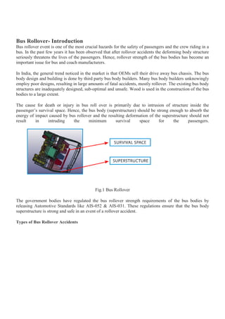
  • 1. Bus Rollover Simulation & AnalysisShare Bus Rollover- Introduction Bus rollover event is one of the most crucial hazards for the safety of passengers and the crew riding in a bus. In the past few years it has been observed that after rollover accidents the deforming body structure seriously threatens the lives of the passengers. Hence, rollover strength of the bus bodies has become an important issue for bus and coach manufacturers. In India, the general trend noticed in the market is that OEMs sell their drive away bus chassis. The bus body design and building is done by third party bus body builders. Many bus body builders unknowingly employ poor designs, resulting in large amounts of fatal accidents, mostly rollover. The existing bus body structures are inadequately designed, sub-optimal and unsafe. Wood is used in the construction of the bus bodies to a large extent. The cause for death or injury in bus roll over is primarily due to intrusion of structure inside the passenger’s survival space. Hence, the bus body (superstructure) should be strong enough to absorb the energy of impact caused by bus rollover and the resulting deformation of the superstructure should not result in intruding the minimum survival space for the passengers. Fig.1 Bus Rollover The government bodies have regulated the bus rollover strength requirements of the bus bodies by releasing Automotive Standards like AIS-052 & AIS-031. These regulations ensure that the bus body superstructure is strong and safe in an event of a rollover accident. Types of Bus Rollover Accidents
  • 2. Mainly there are 2 possible cases of bus rollover accidents. Fig.2 Bus Rollover Cases The case that needs to be considered for compliance mainly depends on the usability of the vehicle. A city bus has to run on good quality roads and the possibility of roll over is only during high speed cornering (E.g. BRTS Corridor), so Case-2 (bus rolls over on ground) will be selected. On the other hand if it is an intercity/tourist bus, the probability of roll over into a ditch is high, Hence Case-1 (bus rolls over into a ditch of 800 mm depth) is selected. However, the structural strength requirement is mostly driven by AIS-031. AIS 031 standard ensures that the bus body superstructure has sufficient strength such that no part of the structure intrudes into the residual space (explained below) of passenger in the event of rollover. Physics behind Bus Rollover Bus rollover is a phenomenon in which the fully laden bus rolls about an axis parallel to the longitudinal direction of the bus passing through the outermost edge of the outermost tyre (Right/Left/Front/Rear) on ground. Bus rollover happens due to collision or high speed during cornering. As a vehicle rounds a corner, three forces act on it: tire forces (the centripetal force), inertial effects (the centrifugal force), and gravity. The cornering forces from the tire push the vehicle towards the center of the curve. This force acts at ground level, below the center of mass. The force of inertia acts horizontally through the vehicle's center of mass away from the center of the turn. These two forces make the vehicle roll towards the outside of the curve. The force of the vehicle's weight acts downward through the center of mass in the opposite direction. When the tire and inertial forces are enough to overcome the force of gravity, the vehicle starts to turn over. Methods for Bus Rollover Analysis Physical Testing During physical testing, the bus placed on platform is tilted about the rotation point (specified as per AIS- 031) with the angular velocity of not more than 0.087 rads/sec. At some specific angle, the bus C.G. imbalances and the bus rolls into the ditch of depth 800 mm due to its own gravity. The intrusion of the side structure into the residual space is checked manually and regulation pass/fail is decided based on the AIS-031 criteria. Computer Aided Engineering - Bus Rollover Simulation
  • 3. In this method the actual case is simulated to an extent that is accurate enough to confirm the protection from rollover. It is a cost effective & less time consuming process. Moreover, bus rollover simulation in comparison to physical testing provides enough scope for optimizing the bus body structure which further helps in reducing the overall weight of the bus. Conventionally many bus body builders go for actual vehicle’s physical testing which incurs huge cost and time. It is advisable to achieve the same result with bus rollover simulation. The method is explained in brief below. For bus rollover simulation we require final angular velocity of the bus during impact on ground & the residual space as per AIS-031 definition. Residual Space Creation Fig.3 Residual space 1. Residual Space (Survival Space) is to be created in the bus as per AIS-031 shown in Fig.3. 2. The position of the "R" point shown in Fig.3 shall be assumed to be 500 mm above the floor under the passenger’s feet, 300 mm from the inner surface of the side of the vehicle and 100 mm in front of the seat back in the Centre-Line of the outboard seats. 3. Height of the Residual space should be minimum 750 mm. Bus Rollover Kinematics It explains the position of rotation points about which bus rolls and calculation of angular velocity with which bus rolls into the ditch.
  • 4. Fig.4 Bus Rollover Kinematics 1. First Rotation (θ1, Position A to B): The bus along with stoppers should be rotated about the bottom point of rear wheel stopper (O1) till the CoG of bus reaches maximum height (Unstable position). 2. Second Rotation (θ2, Position B to C): The bus excluding stoppers should be rotated about the top most point (O2) of the rear stopper (Point height=80 mm) till it touches impact floor. (Note: Keep 1-1.5 mm gap between Impact floor and part which comes first in contact)  Angular velocity is calculated by using formula: (Refer Fig.5) 1/2 IRA ω2 = M * g * ∆H Where, IRA = ICOG_XX + Mass * D2 (Mass moment of inertia about rotational axis) ∆H = Height between Max. CoG & Final CoG D = Distance between CoG and Second point of rotation O2 ω= Angular Velocity M = Total mass of the bus g = Acceleration due to gravity CAE- Bus Rollover Simulation Bus rollover simulation can be performed in several ways (1D/2D/3D mesh) & using various softwares, but the most appropriate method & softwares are considered in terms of accuracy and speed of solution. The CAE simulation includes four major steps, viz. CAD Preparation, Rollover Kinematics, Residual Space, Deck Pre-processing, Deck Solving and Post-processing as described below. Deck Pre-processing 1. Accurate finite element 2D mesh model is prepared from the CAD model of the bus super structure & chassis. 2. Connections i.e. welding and bolts are modelled using 1-D elements. 3. All components mounted on the structure are either meshed or used as lumped mass (0D Mesh). 4. The overall weight & CoG of the bus is matched with the actual bus. 5. Assignment of Material properties. 6. Application of Gravity load at global CoG of bus and Angular velocity to all components of bus. 7. Assignment of Termination time, Time step required for simulation and output files needed for post processing. Solution
  • 5.  The Deck prepared should be imported in solver and number of CPU’s required for run should be mentioned.  Check for any errors; make corrections as per error and Rerun the analysis.  Check for mass addition and percentage increase mass.  Run the Solution, this generally takes 24 Hours to solve the mathematical model. Post-processing  Check energy balance i.e. Total Energy, Internal Energy, Kinetic Energy, Rigid Wall energy and Sliding Interface Energy of each component of bus. Fig.5 Energy balance  Gap Measurement: Fig.6 Gap measurement between residual space and pillars  If gap is more than 5 mm, then the structure is not penetrating into the residual spaces and it passes AIS-031.  If gap is less than 5 mm, then the structure fails and suitable countermeasures need be taken. Factors Affecting Bus Rollover Performance Position of Centre of Gravity (CoG)
  • 6. Stability of bus while turning is dependent on the position of CoG of bus. If height of bus CoG is more, the bus will be more prone to rollover than one having low CoG. Also as height of CoG increases, the radius of rotation will increase, which increases the kinetic energy in structure before impact resulting more damage to superstructure. Fig.7 Position of CoG Hence, during design proper caution should be taken to ensure minimum CoG of the Bus. Number and Position of Pillars As the structural pillars absorb energy during roll over impact, it is necessary to optimise the no of pillars. More no of pillars will add unnecessary weight and less no of pillars will fail in rollover simulation. Tubes Cross Section The strength of the structure is mostly depending on the cross section of the tubes used in the structure. If the bus is failing in rollover analysis, the strength of the structure can be increased by increasing cross section (Breadth, width or thickness) of crucial members in rollover analysis. Material Properties The stronger the material, the stronger the bus is against rollover. Material should absorb more energy of impact by deforming rather than failing. Aluminium can be used for stretch panels which weighs less and absorbs more energy. Reinforcement Optimization
  • 7. Fig.8 Failure Bus Rollover Simulation & Analysis Share Bus Rollover- Introduction Bus rollover event is one of the most crucial hazards for the safety of passengers and the crew riding in a bus. In the past few years it has been observed that after rollover accidents the deforming body structure seriously threatens the lives of the passengers. Hence, rollover strength of the bus bodies has become an important issue for bus and coach manufacturers. In India, the general trend noticed in the market is that OEMs sell their drive away bus chassis. The bus body design and building is done by third party bus body builders. Many bus body builders unknowingly employ poor designs, resulting in large amounts of fatal accidents, mostly rollover. The existing bus body structures are inadequately designed, sub-optimal and unsafe. Wood is used in the construction of the bus bodies to a large extent. The cause for death or injury in bus roll over is primarily due to intrusion of structure inside the passenger’s survival space. Hence, the bus body (superstructure) should be strong enough to absorb the energy of impact caused by bus rollover and the resulting deformation of the superstructure should not result in intruding the minimum survival space for the passengers.
  • 8. Fig.1 Bus Rollover The government bodies have regulated the bus rollover strength requirements of the bus bodies by releasing Automotive Standards like AIS-052 & AIS-031. These regulations ensure that the bus body superstructure is strong and safe in an event of a rollover accident. Types of Bus Rollover Accidents Mainly there are 2 possible cases of bus rollover accidents. Fig.2 Bus Rollover Cases The case that needs to be considered for compliance mainly depends on the usability of the vehicle. A city bus has to run on good quality roads and the possibility of roll over is only during high speed cornering (E.g. BRTS Corridor), so Case-2 (bus rolls over on ground) will be selected. On the other hand if it is an intercity/tourist bus, the probability of roll over into a ditch is high, Hence Case-1 (bus rolls over into a ditch of 800 mm depth) is selected. However, the structural strength requirement is mostly driven by AIS-031. AIS 031 standard ensures that the bus body superstructure has sufficient strength such that no part of the structure intrudes into the residual space (explained below) of passenger in the event of rollover. Physics behind Bus Rollover Bus rollover is a phenomenon in which the fully laden bus rolls about an axis parallel to the longitudinal direction of the bus passing through the outermost edge of the outermost tyre (Right/Left/Front/Rear) on ground. Bus rollover happens due to collision or high speed during cornering. As a vehicle rounds a corner, three forces act on it: tire forces (the centripetal force), inertial effects (the centrifugal force), and gravity. The cornering forces from the tire push the vehicle towards the center of the curve. This force acts at ground level, below the center of mass. The force of inertia acts horizontally through the vehicle's center of mass away from the center of the turn. These two forces make the vehicle roll towards the outside of the curve. The force of the vehicle's weight acts downward through the center of mass in the opposite direction. When the tire and inertial forces are enough to overcome the force of gravity, the vehicle starts to turn over. Methods for Bus Rollover Analysis
  • 9. Physical Testing During physical testing, the bus placed on platform is tilted about the rotation point (specified as per AIS- 031) with the angular velocity of not more than 0.087 rads/sec. At some specific angle, the bus C.G. imbalances and the bus rolls into the ditch of depth 800 mm due to its own gravity. The intrusion of the side structure into the residual space is checked manually and regulation pass/fail is decided based on the AIS-031 criteria. Computer Aided Engineering - Bus Rollover Simulation In this method the actual case is simulated to an extent that is accurate enough to confirm the protection from rollover. It is a cost effective & less time consuming process. Moreover, bus rollover simulation in comparison to physical testing provides enough scope for optimizing the bus body structure which further helps in reducing the overall weight of the bus. Conventionally many bus body builders go for actual vehicle’s physical testing which incurs huge cost and time. It is advisable to achieve the same result with bus rollover simulation. The method is explained in brief below. For bus rollover simulation we require final angular velocity of the bus during impact on ground & the residual space as per AIS-031 definition. Residual Space Creation Fig.3 Residual space
  • 10. 1. Residual Space (Survival Space) is to be created in the bus as per AIS-031 shown in Fig.3. 2. The position of the "R" point shown in Fig.3 shall be assumed to be 500 mm above the floor under the passenger’s feet, 300 mm from the inner surface of the side of the vehicle and 100 mm in front of the seat back in the Centre-Line of the outboard seats. 3. Height of the Residual space should be minimum 750 mm. Bus Rollover Kinematics It explains the position of rotation points about which bus rolls and calculation of angular velocity with which bus rolls into the ditch. Fig.4 Bus Rollover Kinematics 1. First Rotation (θ1, Position A to B): The bus along with stoppers should be rotated about the bottom point of rear wheel stopper (O1) till the CoG of bus reaches maximum height (Unstable position). 2. Second Rotation (θ2, Position B to C): The bus excluding stoppers should be rotated about the top most point (O2) of the rear stopper (Point height=80 mm) till it touches impact floor. (Note: Keep 1-1.5 mm gap between Impact floor and part which comes first in contact)  Angular velocity is calculated by using formula: (Refer Fig.5) 1/2 IRA ω2 = M * g * ∆H Where, IRA = ICOG_XX + Mass * D2 (Mass moment of inertia about rotational axis) ∆H = Height between Max. CoG & Final CoG D = Distance between CoG and Second point of rotation O2 ω= Angular Velocity
  • 11. M = Total mass of the bus g = Acceleration due to gravity CAE- Bus Rollover Simulation Bus rollover simulation can be performed in several ways (1D/2D/3D mesh) & using various softwares, but the most appropriate method & softwares are considered in terms of accuracy and speed of solution. The CAE simulation includes four major steps, viz. CAD Preparation, Rollover Kinematics, Residual Space, Deck Pre-processing, Deck Solving and Post-processing as described below. Deck Pre-processing 1. Accurate finite element 2D mesh model is prepared from the CAD model of the bus super structure & chassis. 2. Connections i.e. welding and bolts are modelled using 1-D elements. 3. All components mounted on the structure are either meshed or used as lumped mass (0D Mesh). 4. The overall weight & CoG of the bus is matched with the actual bus. 5. Assignment of Material properties. 6. Application of Gravity load at global CoG of bus and Angular velocity to all components of bus. 7. Assignment of Termination time, Time step required for simulation and output files needed for post processing. Solution  The Deck prepared should be imported in solver and number of CPU’s required for run should be mentioned.  Check for any errors; make corrections as per error and Rerun the analysis.  Check for mass addition and percentage increase mass.  Run the Solution, this generally takes 24 Hours to solve the mathematical model. Post-processing  Check energy balance i.e. Total Energy, Internal Energy, Kinetic Energy, Rigid Wall energy and Sliding Interface Energy of each component of bus.
  • 12. Fig.5 Energy balance  Gap Measurement: Fig.6 Gap measurement between residual space and pillars  If gap is more than 5 mm, then the structure is not penetrating into the residual spaces and it passes AIS-031.  If gap is less than 5 mm, then the structure fails and suitable countermeasures need be taken. Factors Affecting Bus Rollover Performance Position of Centre of Gravity (CoG) Stability of bus while turning is dependent on the position of CoG of bus. If height of bus CoG is more, the bus will be more prone to rollover than one having low CoG. Also as height of CoG increases, the
  • 13. radius of rotation will increase, which increases the kinetic energy in structure before impact resulting more damage to superstructure. Fig.7 Position of CoG Hence, during design proper caution should be taken to ensure minimum CoG of the Bus. Number and Position of Pillars As the structural pillars absorb energy during roll over impact, it is necessary to optimise the no of pillars. More no of pillars will add unnecessary weight and less no of pillars will fail in rollover simulation. Tubes Cross Section The strength of the structure is mostly depending on the cross section of the tubes used in the structure. If the bus is failing in rollover analysis, the strength of the structure can be increased by increasing cross section (Breadth, width or thickness) of crucial members in rollover analysis. Material Properties The stronger the material, the stronger the bus is against rollover. Material should absorb more energy of impact by deforming rather than failing. Aluminium can be used for stretch panels which weighs less and absorbs more energy. Reinforcement Optimization
  • 14. Fig.8 Failure locations As shown in the fig.9, the superstructure fails at the shown junction points. To avoid that we can increase the tube's cross-section, but that will increase the overall weight of the bus. Hence, it is advised to provide local stiffeners, it adds less weight and increases the strength of the bus against rollover. - Rushikesh Savant Advanced Structures India Pvt Ltd is an independent automotive product development company based out of Bangalore, India with operations in India, China and US. Above is a blog entry from our engineers about Bus Rollover. We can be contacted on business@advancedstructures.in for business enquiries and careers@advancedstructures.in for open positions locations As shown in the fig.9, the superstructure fails at the shown junction points. To avoid that we can increase the tube's cross-section, but that will increase the overall weight of the bus. Hence, it is advised to provide local stiffeners, it adds less weight and increases the strength of the bus against rollover. - Rushikesh Savant
  • 15. Advanced Structures India Pvt Ltd is an independent automotive product development company based out of Bangalore, India with operations in India, China and US. Above is a blog entry from our engineers about Bus Rollover. We can be contacted on business@advancedstructures.in for business enquiries and careers@advancedstructures.in for open positions