Descargar como PDF, PPTX
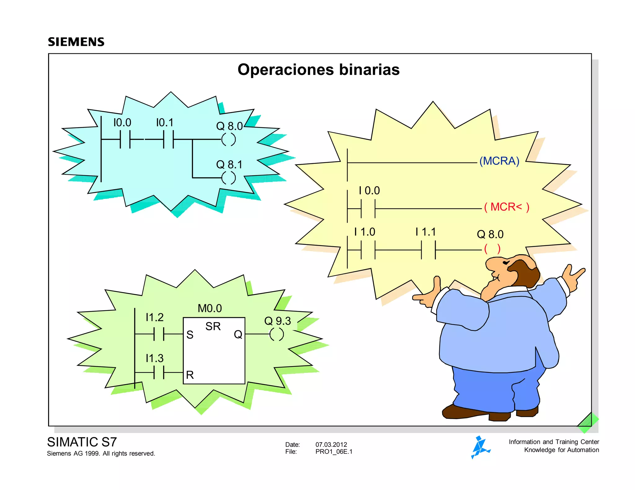


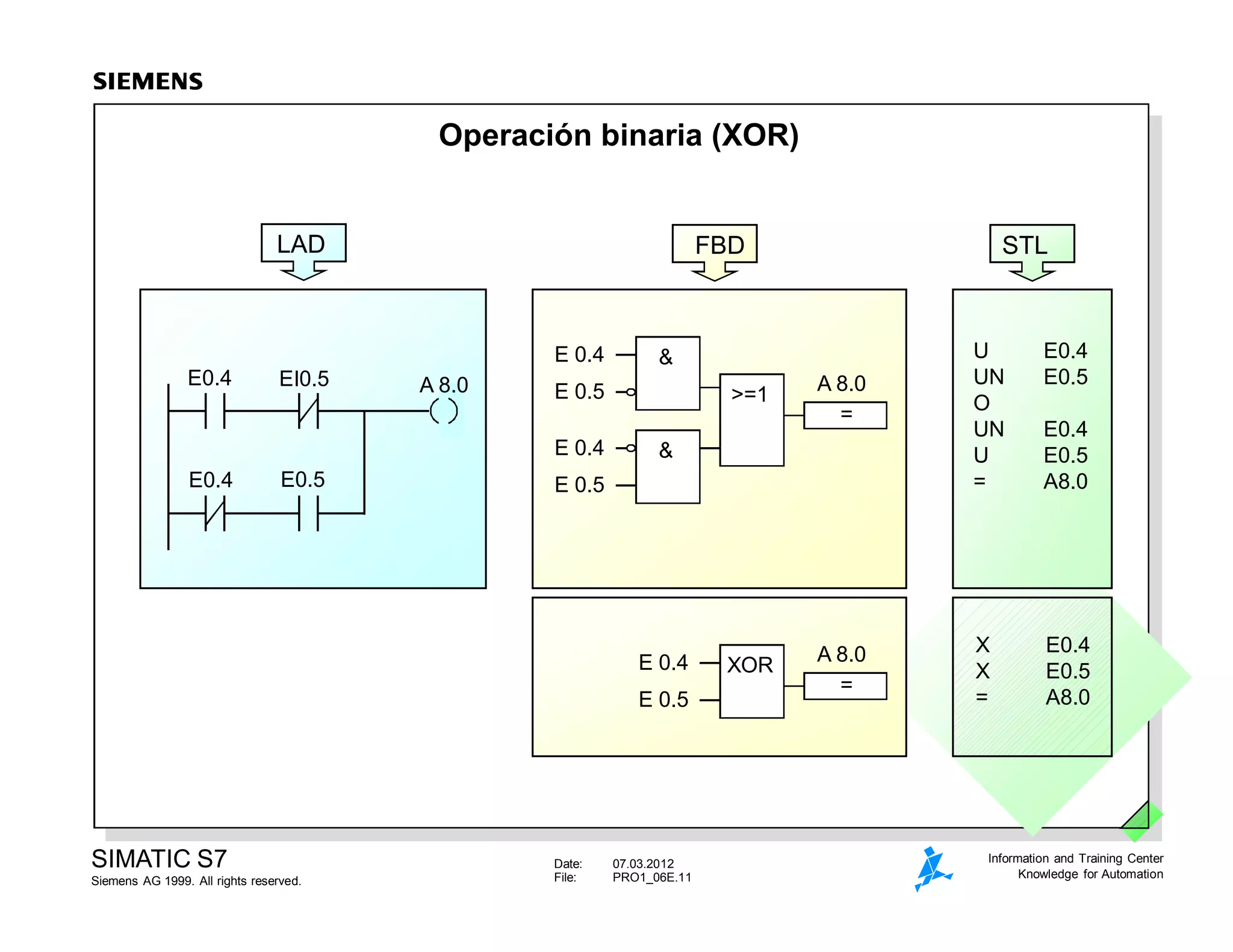

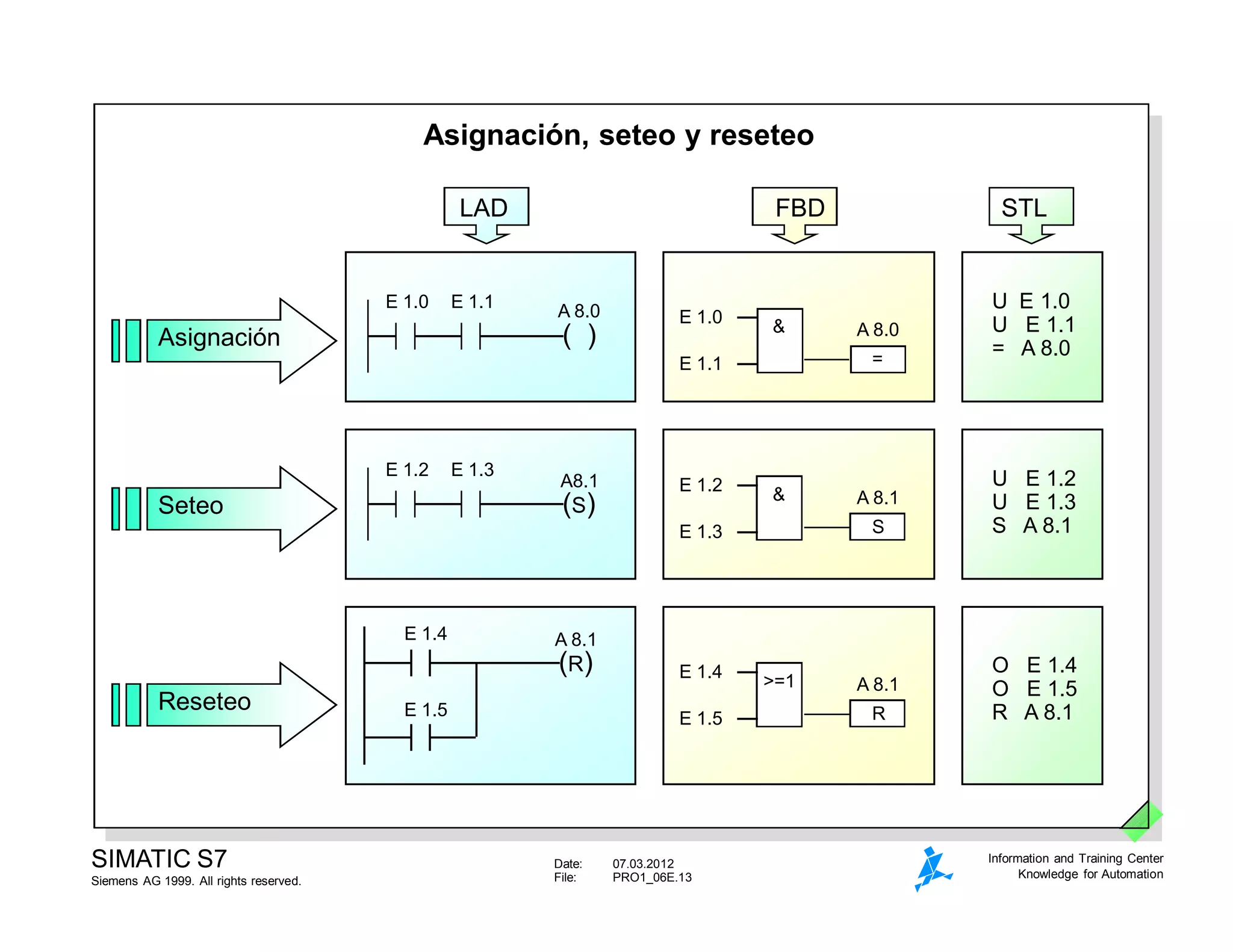


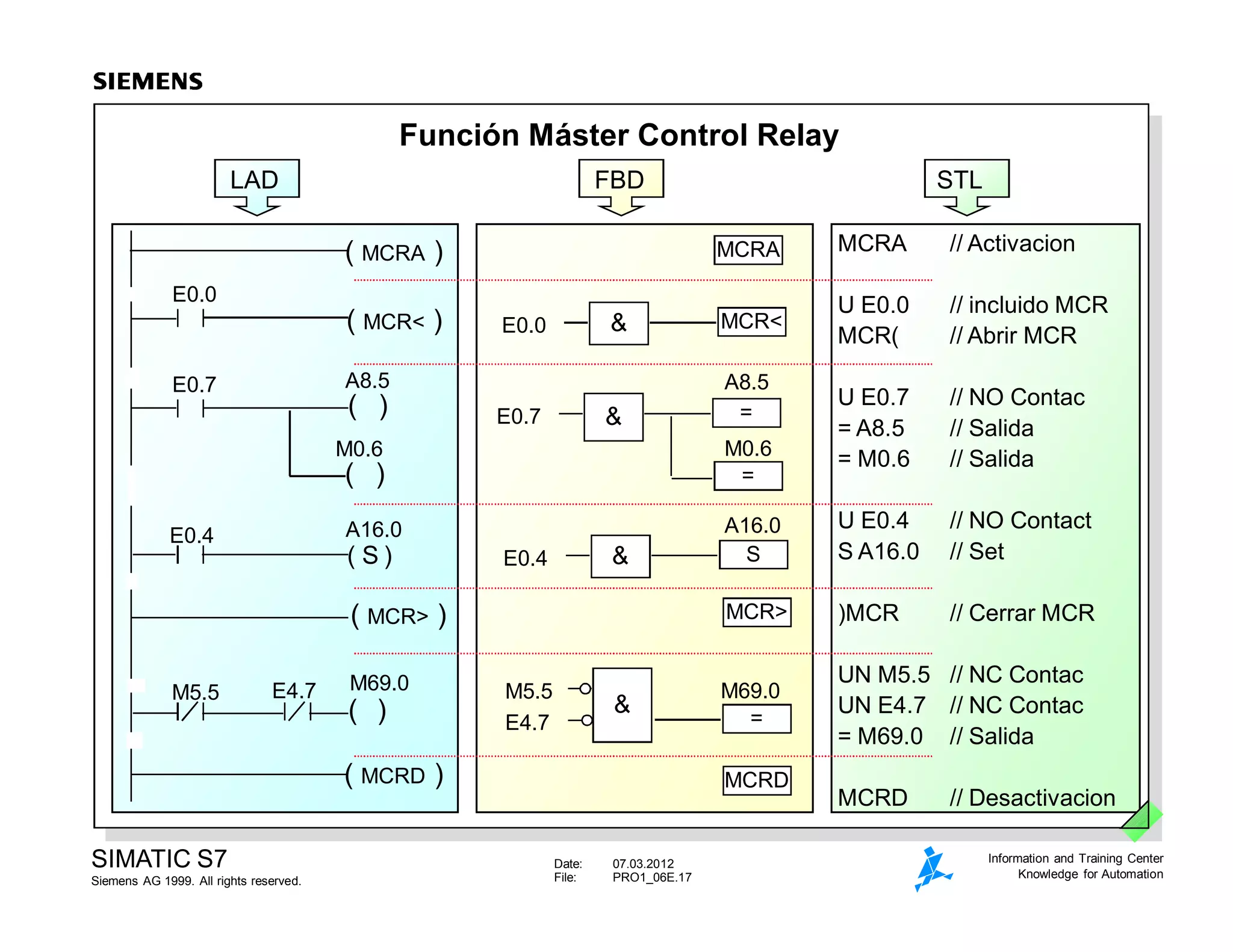


El documento contiene información sobre operaciones binarias lógicas como AND, OR y XOR en diferentes lenguajes de programación como LAD, FBD y STL. También incluye ejemplos de asignación, seteo, reseteo y funciones como set/reset flip-flop y la función máster control relay.


