SlideShare una empresa de Scribd logo
1 de 72
Descargar para leer sin conexión
Please read these instructions before operating the product.
www.DEWALT.com
E
NL
GR
PT
FIN
HU
BG
LV
ES
DK
CZ
E
NO
SK
RO
LT
F
SE
RU
PT
PL
SI
EE
TR
HR
DW0165, DW0165S, DW0330S
User Manual
DW0165S
1
2
0.000 m
0.000 m
0.000 m
0.000 m
50.0°
DW0165S
B
D
AAAA
A
A
AAA
AAA
AAA
2
Figures
A
4
DW0165
4.5V DC
2
5
6
1
3
7 8
C
3 1
2
4
5
6
0.0000 m
0.0000 m
0.0000 m
0.0000 m
50.0°
50.0°
0.0000 m
0.0000 m
0.0000 m
0.0000 m
50.0°
=
=
=
=
ft/m
4
Figures
H
J
K
0.0000 m
0.0000 m
0.0000 m
0.7000m
50.0°
I
71.77 in
45.86 in
45.86 in
50.0°
max
min
+
0.3000 m
0.7000 m
1.0000m
50.0°
+ -
/
0.8500m
-
50.0°
0.1500 m
1.0000 m
+ -
/
5
L
0.6000 m
0.4000 m
0.2400 m
50.0°
2
M
N
O
0.7000 m
0.6000 m
0.5000 m
0.2100m
50.0°
3
2
0.240 m
2
+
0.210 m
0.450 m 2
50.0°
+ -
/
+/-
+/-
6
Figures
1.0100m
2.7390 m
50.0°
2.1000 m
?
P
Q
?
R
7
4.8270m
24.3°
0.0320 m
24.3°
?
S
T
8
Figures
12”
12”
12”
0.000 in
0.00 in
12.0 in
50.0°
a
a
12”
12”
0.000 in
12.0 in
12.0 in
50.0°
a
a
12” 12”
0.000 in
12.0 in
12.0 in
50.0°
a
a
12”
U
9
180°
90°
180°
X
15.0°
15.0°
50.0°
V
?
W
10
E Contents
• User Safety
• Battery Safety
• Loading Batteries
• Turning the Tool On
• Choosing the Settings
• Taking Measurements
• Calibrating the Tool
• Warranty
• Specifications
• Error Codes
Retain all sections of this manual for future
reference.
User Safety
WARNING:
Carefully read the Safety Instructions and
Product Manual before using this product.
The person responsible for the product must
ensure that all users understand and adhere
to these instructions.
WARNING:
The following label information is placed on
your laser tool to inform you of the laser class
for your convenience and safety.
DW0165
4.5V DC
DW0165S
FCC ID: 2ANWF-DW0165
IC: 23237-DW0165
4.5V DC
The DW0165/DW0165S/DW0330S tool emits a visible
laser beam, as shown in Figure A 1 . The laser
beam emitted is Laser Class 2 per IEC 60825-1 and
complies with 21 CFR 1040.10 and 1040.11 except
for deviations pursuant to Laser Notice No. 50, dated
June 24, 2007.
WARNING:
While the laser tool is in operation, be careful
not to expose your eyes to the emitting laser
beam (red light source). Exposure to a laser
beam for an extended time period may be
hazardous to your eyes. Do not look into the
beam with optical aids.
WARNING: To reduce the risk of injury,
user must read the Product User manual,
Laser Safety manual, and Battery Safety
information.
FCC Compliance
This device complies with Part 15 of the FCC Rules.
Operation is subject to the following two conditions: (1)
This device may not cause harmful interference, and
(2) this device must accept any interference received,
including interference that may cause undesired
operation.
FCC Statement
This equipment has been tested and found to
comply with the limits for a Class B digital device,
pursuant to part 15 of the FCC rules. These limits are
designed to provide reasonable protection against
harmful interference in a residential installation. This
equipment generates, uses, and can radiate radio
frequency energy and, if not installed and used in
accordance with the instructions, may cause harmful
interference to radio communications. This device is
a portable unit. The exclusion threshold is 0.8873.
However, there is no guarantee that interference will
not occur in a particular installation. If this equipment
does cause harmful interference to radio or television
reception, which can be determined by turning the
equipment off and on, the user is encouraged to try to
correct the interference by one or more of the following
measures:
- Reorient or relocate the receiving antenna.
- Increase the separation between the equipment and
the receiver.
- Connect the equipment into an outlet on a different
circuit (not the circuit to which the receiver is
connected).
DW0330S
FCC ID: 2ANWFDW0330
IC: 23237-DW0330
4.5V DC
11
E
- Consult the dealer or an experienced radio/TV
technician for help.
Canada, Industry Canada (IC) Notices
Class B digital circuitry of this device complies with
Canadian ICES-003. This device complies with
Industry Canada license-exempt RSS standard(s).
Operation is subject to the following two conditions:
(1) this device may not cause interference, and (2)
this device must accept any interference, including
interference that may cause undesired operation of
the device.
Under Industry Canada regulations, the radio
transmitter(s) in this device may only operate using
an antenna of a type and maximum (or lesser) gain
approved for the transmitter by Industry Canada. To
reduce potential radio interference to other users, the
antenna type and its gain should be so chosen that
the equivalent isotropically radiated power (e.i.r.p.)
is not more than that necessary for successful
communication.
Battery Safety
WARNING: Batteries can explode or leak
and cause serious injury or fire. To reduce the
risk:
ALWAYS follow all instructions and warnings
on the battery label and package.
DO NOT short any battery terminals.
DO NOT charge alkaline batteries.
DO NOT mix old and new batteries. Replace
all of them at the same time with new
batteries of the same brand and type.
DO NOT mix battery chemistries.
DO NOT dispose of batteries in fire.
ALWAYS keep batteries out of reach of
children.
ALWAYS remove batteries if the device will
not be used for several months.
NOTE: Ensure that the recommended
batteries are used.
NOTE: Ensure the batteries are inserted in
the correct manner, with the correct polarity.
Loading Batteries
1. Pull up the endpiece on the back of the tool
(Figure D 1 ).
2. Pull up the battery compartment latch on the back
of the tool (Figure D 2 and D 3 ).
3. Insert three AAA batteries, making sure to position
the - and + ends of each battery as noted inside
the battery compartment (Figure D 4 ).
4. Push the battery door down until it snaps in place
(Figure D 5 ).
When the tool is ON, the battery level appears on the
screen (Figure C 1 ).
Turning the Tool On
1. Point the tool's laser (Figure A 1 ) toward a wall
or object, and not toward anyone's eyes.
2. Press (Figure A 3 ) to turn the tool on
and display the red laser dot.
Choosing the Settings
Setting Automatic Turn Off
By default, the tool will automatically turn off
90 seconds after no buttons or options have been
selected. To change when the tool automatically turns
off, follow these steps.
1. On the first screen (Figure E 1 ), press to
display the Main Menu.
2. On the Main Menu (Figure E 2 ), select and
press .
3. On the Settings Menu (Figure G ), select and
press .
4. Select the time.
• Choose to turn off the tool after 30 sec, 60 secs,
90 secs, or 300 secs.
• To keep the tool turned on until you manually
turn it off (by pressing and holding for
10 seconds), select ∞.
5. Press to save your setting.
12
E Setting Screen Brightness
By default, the tool's screen will be set at 25%
brightness. To change the brightness level, follow
these steps.
1. On the first screen (Figure E 1 ), press to
display the Main Menu.
2. On the Main Menu (Figure E 2 ), select and
press .
3. On the Settings Menu (Figure G ), select and
press .
4. Select the desired brightness level: 25%, 50%,
75%, or 100%.
5. Press to save your new setting.
Turning Off the Sound
By default, the tool will beep each time you take a
measurement. You can turn off the beeps.
1. On the first screen (Figure E 1 ), press to
display the Main Menu.
2. On the Main Menu (Figure E 2 ), select and
press .
3. On the Settings Menu (Figure G ), select and
press to display .
4. Press to save your setting.
Changing the Unit of Measure ft/m
By default, the tool will display measurements in
inches (74 9/16 in). You can change the unit of
measure to fractional ft (6'029/16), meters (1.8940 m),
decimal ft (6.21 ft), or decimal inches (3.21 in).
1. On the first screen (Figure E 1 ), press to
display the Main Menu.
2. On the Main Menu (Figure E 2 ), select and
press .
3. On the Settings Menu (Figure G ), select ft/m
and press .
4. Select the unit of measure.
• 0'00 0/00
• 0 0/00
• 0'00 ft
• 0.00 in
• 0.0000 m
5. Press to save your setting.
Choosing the Tool Position
By default, distances are measured from the bottom
of the tool to a wall or object (Figure F 3 ). To
measure distances from a different tool location, follow
these steps.
1. On the first screen (Figure E 1 ), press to
display the Main Menu.
2. On the Main Menu (Figure E 2 ), select and
press .
3. Select the tool position.
• To measure from the top of the tool
(Figure F 1 ), select .
• To measure from the tripod connection on the
tool (Figure F 2 ), select .
• To measure from a corner or another hard-to-
reach location with the endpiece flipped open
(Figure D 1 ), select (Figure F 4 ) to
measure from the end of the endpiece.
4. Press to save your new setting.
Taking Measurements
Measuring Distance
1. Point the tool's laser (Figure A 1 ) toward a wall
or object, and not toward anyone's eyes.
2. Press (Figure A 3 ) to turn the tool on
and display the red laser dot.
3. Make sure the tool position setting (Figure C 4 )
is correct for taking the measurement.
4. Point the tool's laser (Figure A 1 ) toward
the wall or object whose distance you need to
measure (Figure H 1 ).
13
E
5. Press to measure the distance from the
tool to the wall or object.
6. At the bottom of the screen, view the current
measurement (Figure H 2 ).
To take a new measurement, press to move
the current measurement up to the previous line on
the screen. Then repeat steps 4-6.
Adding 2 Measurements
You can add two measurements to get a total
measurement of the two distances (Figure I ).
1. Point the tool's laser (Figure A 1 ) toward a wall
or object, and not toward anyone's eyes.
2. Press (Figure A 3 ) to turn the tool on
and display the red laser dot.
3. Make sure the tool position setting (Figure C 4 )
is correct for taking the measurement.
4. Select as the measurement type.
• Press to display the Main Menu
(Figure E 2 )
• Press to select .
• Press to display the Measurement Type
Menu (Figure E 3 ).
• Press the arrow buttons to select .
• Press .
5. Press to indicate that you want to add two
measurements.
6. Point the tool's laser toward the wall or object
whose distance you need to measure
(Figure I 1 ).
7. Press to measure the distance from the
tool to the first wall or object.
8. Point the tool's laser toward the next wall or object
(Figure I 2 ).
9. Press to measure the distance and add it
to the previous measurement.
10. View the total of the two measurements at the
bottom of the screen (Figure I 3 ).
Subtracting 2 Measurements
You can subtract one measurement from another
(Figure J ).
1. Point the tool's laser (Figure A 1 ) toward a wall
or object, and not toward anyone's eyes.
2. Press (Figure A 3 ) to turn the tool on
and display the red laser dot.
3. Make sure the tool position setting (Figure C 4 )
is correct for taking the measurement.
4. Select as the measurement type.
• Press to display the Main Menu
(Figure E 2 ).
• Press to select .
• Press to display the Measurement Type
Menu (Figure E 3 ).
• Press the arrow buttons to select .
• Press .
5. Press to indicate that you want to subtract
one measurement from another.
6. Point the tool's laser toward the wall or object
whose distance you need to measure
(Figure J 1 ).
7. Press to measure the distance from the
tool to the wall or object.
8. Point the tool's laser toward the wall or object
whose distance is to be subtracted from the first
measurement (Figure J 2 ).
9. Press to measure the distance and
subtract it from the previous measurement.
10. View the difference between the two
measurements at the bottom of the screen
(Figure J 3 ).
14
E Measuring Continuously
To take a series of measurements as you move
around, change to Continuous Measure mode
(Figure K ).
1. Point the tool's laser (Figure A 1 ) toward a wall
or object, and not toward anyone's eyes.
2. Press Figure A 3 ) to turn the tool on
and display the red laser dot.
3. Make sure the tool position setting (Figure C 4 )
is correct for taking the measurement.
4. Select as the measurement type.
• Press to display the Main Menu
(Figure E 2 ).
• Press to select .
• Press to display the Measurement Type
Menu (Figure E 3 ).
• Press the arrow buttons to select .
• Press .
5. Point the tool's laser (Figure A 1 ) toward
the wall or object whose distance you need to
measure (Figure K 1 ).
6. At the bottom of the screen, view the current
measurement (Figure K 2 ), which will keep
changing as you move the tool.
7. To take the current measurement (from the tool to
the wall or object) and exit Continuous Measure
mode, press .
To take a new measurement, press to move
the current measurement up to the previous line on
the screen. Then repeat steps 4-7.
Measuring Area
You can measure the area of a wall, floor, or object
(Figure L ).
1. Point the tool's laser (Figure A 1 ) toward a wall
or object, and not toward anyone's eyes.
2. Press (Figure A 3 ) to turn the tool on
and display the red laser dot.
3. Make sure the tool position setting (Figure C 4 )
is correct for taking the measurement.
4. Select as the measurement type.
• Press to display the Main Menu
(Figure E 2 ).
• Press to select .
• Press to display the Measurement Type
Menu (Figure E 3 ).
• Press the arrow buttons to select .
• Press .
5. Measure the width (Figure L 1 ).
• Point the top of the tool at one side of the wall,
floor, or object.
• Position the tool at one end of the wall, floor,
or object and point the laser dot across the
width. (Figure L 1 shows where to position
the tool if you are measuring from the bottom
of the tool.)
• Press to display the width measurement
at the top of the screen.
6. Measure the length (Figure L 2 ).
• Position the tool at one end of the wall, floor,
or object and point the laser dot across the
length. (Figure L 2 shows where to position
the tool if you are measuring from the bottom
of the tool.)
• Press to display the length measurement
on the second line of the screen.
7. View the Area measurement at the bottom of the
screen (Figure L 3 ).
Adding/Subtracting 2 Areas
You can measure the area of a wall, floor, or object
and then add it to, or subtract it from, the area of
another wall, floor, or object (Figure M ).
1. Point the tool's laser (Figure A 1 ) toward a wall
or object, and not toward anyone's eyes.
2. Press (Figure A 3 ) to turn the tool on
and display the red laser dot.
3. Make sure the tool position setting (Figure C 4 )
is correct for taking the measurement.
15
E
4. Select as the measurement type.
• Press to display the Main Menu
(Figure E 2 ).
• Press to select .
• Press to display the Measurement Type
Menu (Figure E 3 ).
• Press the arrow buttons to select .
• Press .
5. Press to add, or to subtract, the areas of
two walls, floors, or objects.
6. Measure the width of the first wall, floor, or object
(Figure M 1 ).
• Position the tool at one end of the wall, floor,
or object and point the laser dot across the
width. (Figure M 1 shows where to position
the tool if you are measuring from the bottom
of the tool.)
• Press to display the width measurement
at the top of the screen.
7. Measure the length of the first wall, floor, or
object (Figure M 2 ).
• Position the tool at one end of the wall, floor,
or object and point the laser dot across the
length. (Figure M 2 shows where to position
the tool if you are measuring from the bottom
of the tool.)
• Press to display the length measurement
on the second line of the screen.
8. Follow the same steps to measure the width and
length of the second wall, floor, or object.
9. View the Area measurement at the bottom of the
screen (Figure M 3 ).
Measuring Volume
You can measure the volume of a room or object
(Figure N ).
1. Point the tool's laser (Figure A 1 ) toward a wall
or object, and not toward anyone's eyes.
2. Press (Figure A 3 ) to turn the tool on.
3. Make sure the tool position setting (Figure C 4 )
is correct for taking the measurement.
4. Select as the measurement type.
• Press to display the Main Menu
(Figure E 2 ).
• Press to select .
• Press to display the Measurement Type
Menu (Figure E 3 ).
• Press the arrow buttons to select .
• Press .
5. Measure the width (Figure N 1 ).
• Point the top of the tool at one side of the target
(room or object).
• Position the tool at one end of the target and
point the laser dot across the width.
(Figure N 1 shows where to position the
tool if you are measuring from the bottom of
the tool.)
• Press to display the width measurement
at the top of the screen.
6. Measure the length (Figure N 2 ).
• Position the tool at one end of the target and
point the laser dot across the length.
(Figure N 2 shows where to position the
tool if you are measuring from the bottom of
the tool.)
• Press to display the length measurement
on the second line of the screen.
7 Measure the height (Figure N 3 ).
• Position the tool at one end of the target and
point the laser dot across the height. (Figure N
3 shows where to position the tool if you are
measuring from the bottom of the tool).
• Press to display the height measurement
on the third line of the screen.
8. View the Volume measurement at the bottom of
the screen (Figure N 4 ).
16
E Adding/Subtracting 2 Volumes
You can measure the volume of room or object
and then add it to, or subtract it from, the volume of
another room or object (Figure O ).
1. Point the tool's laser (Figure A 1 ) toward a wall
or object, and not toward anyone's eyes.
2. Press (Figure A 3 ) to turn the tool on
and display the red laser dot.
3. Make sure the tool position setting (Figure C 4 )
is correct for taking the measurement.
4. Select as the measurement type.
• Press to display the Main Menu
(Figure E 2 ).
• Press to select .
• Press to display the Measurement Type
Menu (Figure E 3 ).
• Press the arrow buttons to select .
• Press .
5. Press to add, or to subtract, the volumes
of two rooms or objects.
6. Measure the width (Figure O 1 ).
• Position the tool at one end of the room or
object and point the laser dot across the width.
(Figure O 1 shows where to position the
tool if you are measuring from the bottom of
the tool.)
• Press to display the width measurement
at the top of the screen.
7. Measure the length (Figure O 2 ).
• Position the tool at one end of the room or
object and point the laser dot across the length.
(Figure O 2 shows where to position the
tool if you are measuring from the bottom of
the tool.)
• Press to display the length measurement
on the second line of the screen.
8. Measure the height (Figure O 3 ).
• Position the tool at one end of the room or
object and point the laser dot across the height.
(Figure O 3 shows where to position the
tool if you are measuring from the bottom of
the tool).
• Press to display the height measurement
on the third line of the screen.
9. Follow the same steps to measure the width,
length, and height of the second room or object.
10. View the Volume measurement at the bottom of
the screen (Figure O 4 ).
Measuring the Height of a Tall Object
If you need to measure the height of a tall object
(e.g., a tall building), you can calculate the height
based on the distance to 1 point or the distances
from the same point to 2 points on the object. The
tool will use the Pythagorean Theorem (C2
=A2
+B2
) to
calculate the height.
Distance to 1 Point
You can use the distance to one point on a wall
or object (Indirect Height) to determine its height
(Figure P ).
1. Point the tool's laser (Figure A 1 ) toward a wall
or object, and not toward anyone's eyes.
2. Press (Figure A 3 ) to turn the tool on
and display the red laser dot.
3. Make sure the tool position setting (Figure C 4 )
is correct for taking the measurement.
4. Select as the measurement type.
• Press to display the Main Menu
(Figure E 2 ).
• Press to select .
• Press to display the Measurement Type
Menu (Figure E 3 ).
• Press the arrow buttons to select .
• Press .
5. Position the tool opposite the bottom of the
vertical height to be measured (Figure P 1 ).
17
E
6. Point the laser toward the highest point of the
building or object whose height you need to
measure (Figure P 1 ).
7. Press to measure the distance.
8. View the height measurement at the bottom of the
screen (Figure P 2 ).
Distances to 2 Points
You can use the distance to two points on a wall
or object (Double Indirect Height) to determine its
height (Figure Q ).
1. Point the tool's laser (Figure A 1 ) toward a wall
or object, and not toward anyone's eyes.
2. Press (Figure A 3 ) to turn the tool on
and display the red laser dot.
3. Make sure the tool position setting (Figure C 4 )
is correct for taking the measurement.
4. Select as the measurement type.
• Press to display the Main Menu
(Figure E 2 ).
• Press to select .
• Press to display the Measurement Type
Menu (Figure E 3 ).
• Press the arrow buttons to select .
• Press .
5. Position the tool opposite the approximate
center of the vertical height to be measured
(Figure Q 1 ).
6. Point the laser toward the lowest point of the
building or object whose height you need to
measure (Figure Q 2 ).
7. Press to measure the distance.
8. From the same point, aim the laser at the
highest point of the building or object
(Figure Q 3 ).
9. Press to measure the distance.
10. On the bottom line of the screen, view the height
of the building or object (Figure Q 4 ).
Measuring Partial Height of a Wall
If you need to determine the height of a section of a
wall or object (e.g., the distance from the ceiling to
the top of TV or window on the wall) (Figure R ).
1. Point the tool's laser (Figure A 1 ) toward a wall
or object, and not toward anyone's eyes.
2. Press (Figure A 3 ) to turn the tool on
and display the red laser dot.
3. Make sure the tool position setting (Figure C 4 )
is correct for taking the measurement.
4. Select as the measurement type.
• Press to display the Main Menu
(Figure E 2 ).
• Press to select .
• Press to display the Measurement Type
Menu (Figure E 3 ).
• Press the arrow buttons to select .
• Press .
5. Point the laser at the highest point of the wall or
object (Figure R 1 ).
6. Press to measure the distance to the top
of the tall object.
7. From the same point, aim the laser at the top
of the obstruction on the wall or object
(Figure R 2 ).
8. Press to measure the distance from the
top of the wall to the obstruction (TV, window,
etc.).
9. From the same point, aim the laser on a
horizontal line straight ahead toward the bottom
of the wall (Figure R 3 ).
10. Press to measure the distance.
11. On the bottom line of the screen, view the
distance between the top of the wall and the top
of the obstruction on the wall (Figure R 4 ).
18
E Measuring Height of Obstructed Object -
Follow these steps to determine the height of a tall
building or object that is blocked by other buildings
or objects (Figure S ).
1. Point the tool's laser (Figure A 1 ) toward a wall
or object, and not toward anyone's eyes.
2. Press (Figure A 3 ) to turn the tool on
and display the red laser dot.
3. Make sure the tool position setting (Figure C 4 )
is correct for taking the measurement.
4. Select as the measurement type.
• Press to display the Main Menu
(Figure E 2 ).
• Press to select .
• Press to display the Measurement Type
Menu (Figure E 3 ).
• Press the arrow buttons to select
(Figure E 4 ).
• Press .
5. Point the laser at the highest point of the
building, wall, or object (Figure S 1 ).
6. Press to take the measurement.
7. On the bottom line of the screen, view the height
of the building or object (Figure S 2 ).
Measuring from a Tripod
If you are placing the tool on a tripod to measure
the height of a tall building, follow these steps
(Figure T ).
1. Screw the 1/4-20 hole on the back of the tool
onto the 1/4-20 connection on the top of your
tripod (Figure T 1 ).
2. Point the tool's laser (Figure A 1 ) toward a wall
or object, and not toward anyone's eyes.
3. Press (Figure A 3 ) to turn the tool on
and display the red laser dot.
4. Make sure the tool position setting (Figure C 4 )
is to measure from the tripod connection.
5. Select as the measurement type.
• Press to display the Main Menu
(Figure E 2 ).
• Press to select .
• Press to display the Measurement Type
Menu (Figure E 3 ).
• Press the arrow buttons to select
(Figure E 4 ).
• Press .
6. Point the laser at the lowest point of the wall or
object whose height you need to measure
(Figure T 2 ).
7. Press to take the measurement.
8. Point the laser at other points on the wall or object
(Figure T 3 ).
9. When ready, press to take the
measurement.
10. On the bottom line of the screen, view the height
of the wall or object (Figure T 4 ).
Positioning Studs
a
a
When you are framing a wall, use the Stakeout
feature to easily mark the position of each stud
(Figure U ).
1. Point the tool's laser (Figure A 1 ) toward a wall
or object, and not toward anyone's eyes.
2. Press (Figure A 3 ) to turn the tool on
and display the red laser dot.
3. Make sure the tool position setting (Figure C 4 )
is set to to measure from the back of the tool.
4. Select
a
a as the measurement type.
• Press to display the Main Menu (Figure
E 2 ).
• Press to select .
• Press to display the Measurement Type
Menu (Figure E 3 ).
• Press the arrow buttons to select
a
a
(Figure E 4 ).
• Press .
19
E
5. Determine the distance between each stud, for
example, 12.
6. Press and until the top number on the
screen is set to the distance from the right edge
of one stud to the left edge of the next (e.g., 12)
(Figure U 1 ).
7. Line up the back of the tool with the right edge of
the last stud that is nailed in (Figure U 2 ).
8. Press to start measuring the distance as
you slowly move the tool to the right.
9. Continue moving the tool to the right until the
bottom number on the screen is 0.00 in (Figure
U 3 ).
10. Press to stop measuring.
11. Using a pencil, mark the location where the left
edge of the stud should be nailed into the wall
frame.
12. Nail the left edge of the stud at the marked
location.
13. For each remaining stud in the wall frame, repeat
steps 7-12 (Figure U 4 ).
Measuring an Angle
If you need to determine the angle at which
something is positioned, use the tool to measure that
angle (Figure W ).
1. Point the tool's laser (Figure A 1 ) toward a wall
or object, and not toward anyone's eyes.
2. Press (Figure A 3 ) to turn the tool on
and display the red laser dot.
3. Make sure the tool position setting (Figure C 4 )
is correct for taking the measurement.
4. Select as the measurement type.
• Press to display the Main Menu
(Figure E 2 ).
• Press to select .
• Press to display the Measurement Type
Menu (Figure E 3 ).
• Press the arrow buttons to select .
• Press .
5. Position the tool at the angle to be measured
(Figure W 1 ).
6. Press to take the measurement.
7. View the angle measurement on the screen
(Figure W 2 ).
Using the Tool as a Level
1. Point the tool's laser (Figure A 1 ) toward a wall
or object, and not toward anyone's eyes.
2. Press (Figure A 3 ) to turn the tool on
and display the red laser dot.
3. Select as the measurement type.
• Press to display the Main Menu
(Figure E 2 ).
• Press to select .
• Press to display the Measurement Type
Menu (Figure E 3 ).
• Press the arrow buttons to select .
• Press .
4. Place the tool in the vertical or horizontal position
on the surface that you want to check is level
(Figure V 1 ).
5. On the tool's screen, view the position of the white
bubble on the vial (Figure V 2 ).
20
E Using DW0165S/DW0330S With
If you have a DW0165S or DW0330S, you can use
its Bluetooth® capability to pair it with the DEWALT®
Tool Connect™ application on your cell phone
or tablet, and then mark up room photos with the
measurements you have taken.
1. From either or , download
the DEWALT®
Tool Connect™ application to your
cell phone or tablet.
2. Using the DEWALT®
Tool Connect™ application,
capture the room or space for which you want to
record the measurements, by taking room photos.
3. On the DW0165S or DW0330S keypad, press
to turn on the tool.
4. If appears on the screen (Figure C 2 ), turn
on the Bluetooth® connection.
• On the keypad, press to display the main
menu.
• Select .
• Press to turn on the Bluetooth®
connection.
5. Use the DEWALT®
Tool Connect™ application to
pair your cell phone or tablet to the DW0165S or
DW0330S, and then mark up room photos with
the measurements you have taken.
THE BLUETOOTH® WORD MARK AND LOGOS ARE
REGISTERED TRADEMARKS OWNED BY BLUETOOTH SIG,
INC. AND ANY USE OF SUCH MARKS BY DEWALT IS UNDER
LICENSE. APPLE AND THE APPLE LOGO ARE TRADEMARKS
OF APPLE INC., REGISTERED IN THE U.S. AND OTHER
COUNTRIES. APP STORE IS A SERVICE MARK OF APPLE
INC., REGISTERED IN THE U.S. AND OTHER COUNTRIES.
GOOGLE PLAY AND THE GOOGLE PLAY LOGO ARE TRADE-
MARKS OF GOOGLE INC.
Viewing the Tool's Memory
Up to the last 20 measurements are stored in the
tool's memory.
1. Point the tool's laser (Figure A 1 ) toward a wall
or object, and not toward anyone's eyes.
2. Press (Figure A 3 ) to turn the tool on
and display the red laser dot.
3. Select as the measurement type.
• Press to display the Main Menu
(Figure E 2 ).
• Press to select .
• Press to display the Measurement Type
Menu (Figure E 3 ).
• Press the arrow buttons to select
(Figure E 4 ).
• Press .
4. View the last measurement that was taken. Press
to scroll through all the measurements that
have been stored in the tool's memory (up to 20).
Press to scroll back.
Clearing the Tool's Memory
You can clear one or more measurements that are
currently in the tool's memory.
Clearing a Measurement
1. Point the tool's laser (Figure A 1 ) toward a wall
or object, and not toward anyone's eyes.
2. Press (Figure A 3 ) to turn the tool on
and display the red laser dot.
3. Select as the measurement type.
• Press to display the Main Menu
(Figure E 2 ).
• Press to select .
• Press to display the Measurement Type
Menu (Figure E 3 ).
• Press the arrow buttons to select
(Figure E 4 ).
• Press .
4. Specify which measurement you want to delete:
• To delete a specific measurement, continue
with step 5.
• To delete ALL measurements, skip to step 6.
5. To delete a specific measurement:
• Press or to scroll through the
measurements that have been stored in the
tool's memory (up to 20) until you display the
21
E
measurement to be deleted.
• Press .
• Select and press to delete the
measurement.
6. To delete ALL measurements:
• Press .
• Select and press to delete all
measurements from the tool's memory.
Turning Off the Tool
The tool can be turned off in either of these ways:
• Press and hold for 10 seconds. When
you release after 10 seconds, the tool will
turn off.
• If you do not use the tool for 90 seconds, it will
automatically turn off.
Calibrating the tool
Please note that if you do not position the tool correctly
for each step of the calibration process, will appear
in red on the screen (Figure X ).
1. Point the tool's laser (Figure A 1 ) toward a wall
or object, and not toward anyone's eyes.
2. Press (Figure A 3 ) to turn the tool on
and display the red laser dot.
3. Press to display the Main Menu
(Figure E 2 ).
4. On the Main Menu, select and press .
5. On the Settings Menu (Figure G ), select
and press .
6. Place the tool with the screen facing upward on a
flat, level surface (Figure X 1 ).
7. Press .
8. While the tool is still laying on the level surface,
turn the tool 180° (Figure X 2 ).
9. Press .
10. Flip the long side of the tool 90° so it is laying on
its side (Figure X 3 ).
11. Press .
12. While the tool is still laying on its side, turn the
tool 180° (Figure X 4 ).
13. Press .
14. Make sure appears on the tool's screen
(Figure X 5 ).
Three Year Limited Warranty
DEWALT will repair, without charge, any defects due
to faulty materials or workmanship for three years
from the date of purchase. This warranty does not
cover part failure due to normal wear or tool abuse.
For further detail of warranty coverage and warranty
repair information, visit www.DEWALT.com or call
1–800–4-DEWALT (1–800–433–9258). This warranty
does not apply to accessories or damage caused
where repairs have been made or attempted by
others. This warranty gives you specific legal rights
and you may have other rights which vary in certain
states or provinces.
In addition to the warranty, DEWALT®
tools are
covered by our:
1 YEAR FREE SERVICE
DEWALT will maintain the tool and replace worn parts
caused by normal use, for free, any time during the
first year after purchase.
90 DAY MONEY BACK GUARANTEE
If you are not completely satisfied with the
performance of your DEWALT Power Tool, Laser, or
Nailer for any reason, you can return it within 90 days
from the date of purchase with a receipt for a full
refund - no questions asked.
RECONDITIONED PRODUCT: Reconditioned product
is covered under the 1 Year Free Service Warranty.
The 90 Day Money Back Guarantee and the Three
Year Limited Warranty do not apply to reconditioned
product.
FREE WARNING LABEL REPLACEMENT: If your
warning labels become illegible or are missing, call
1-800-4-DEWALT or visit your local service center for
a free replacement.
22
E
Specifications
DW0165  DW0165S DW0330S
Range 6in to 165ft (0.15m to 50m) 6in to 330ft (0.15m to 100m)
Measuring Accuracy1
up to 10m: 1/16in (1.5mm)
10m-30m: 0.078in/5/64in) additional (+/- 0.15mm/m)
30m: +/- 0.002in/ft (+/- 0.2mm/m)
Resolution2
1/16in (1mm)
Laser Class Class 2 (IEC/EN60825-1: 2014)
Laser Type ≤ 1.0mW @ 630-680nm
Laser Automatic Switch-off 30s
Unit Automatic Switch-off By default, 90s. User can set to 30s, 60s, or 300s
Continuous Measuring Yes
Area Yes
Volume Yes
Pythagoras 2-Point Yes
Endpiece to measure from corners 3
Yes
Battery Life (3 x AAA) Up to 3000 Measurements
(2500 with ; DW0165S  DW0330S)
Dimension (H x D x W) 4.72 x 1.91 x 1.02in (120 x 48.5 x 26mm)
Weight (with Batteries) 9.88oz (280g)
Storage Temperature Range 14° F ~ 140° F (-10° C ~ +60 C)
Operating Temperature Range 32° F ~ 104° F (0° C ~ +40° C)
1
Measuring Accuracy depends on the current conditions:
• Under favorable conditions (good target surface and room temperature), up to 33ft (10m).
• Under unfavorable conditions (bright sunlight, a very weak reflecting target surface, or large temperature fluctuations), the
error can increase by to ± 0.003 in/ft (± 0.25mm/m) for distances over 33ft (10m).
2
Resolution is the finest measurement you can see. In inches, that is 1/16. In mm, that is 1mm.
3
Flip open the endpiece at the bottom of the tool when you need to fit the tool into corners or grooves that are not at 180° angles. If
a corner is at 90°, the endpiece can be used to hold the tool up against something.
Error Codes
If INFO appears on the screen with a Code number, perform the corresponding Corrective Action.
Code Description Corrective Action
101 Received Signal Too Weak,
Measuring Time Too Long
Use the target plate or change the target surface.
102 Received Signal Too High Target is too reflective. Use the target plate or change the
target surface.
201 Too Much Background Light Reduce the background light on the target area.
202 Laser Beam Interrupted Remove the obstacle and repeat the measurement.
301 Temperature Too High Allow the device to cool down to a temperature within the
specified Operating Temperature Range.
302 Temperature Too Low Allow the device to warm up to a temperature within the
specified Operating Temperature Range.
401 Hardware Error Switch the device on/off several times. If the error still occurs,
return the defective device to the Service Center or distributor.
Refer to the Warranty.
402 Unknown Error Contact the Service Center or distributor. Refer to the Warranty.
500 Data Error Contact the Service Center or distributor. Refer to the Warranty.
ES
24
Contenido
• Seguridad del usuario
• Seguridad de la batería
• Carga de baterías
• Encendido de la herramienta
• Elección de los ajustes
• Toma de mediciones
• Calibración de la herramienta
• Garantía
• Especificaciones
• Códigos de error
Conserve todas las secciones de este manual para
futura referencia.
Seguridad del usuario
ADVERTENCIA:
Lea con atención las instrucciones de
seguridad y el manual del producto antes de
usar el producto. La persona responsable
del producto debe asegurarse que todos
los usuarios entiendan y cumplan con estas
instrucciones.
ADVERTENCIA:
La siguiente etiqueta de información
se coloca en su herramienta láser para
informarle sobre la clase de láser para su
comodidad y seguridad.
DW0165
4.5V DC
DW0165S
FCC ID: 2ANWF-DW0165
IC: 23237-DW0165
4.5V DC
La herramienta DW0165/DW0165S/
DW0330S emite un rayo láser visible, como
se muestra en la Figura A 1 . El rayo láser
emitido es un Láser Clase 2 en conformidad
con la norma IEC 60825-1 y cumple las
normas 21 CFR 1040.10 y 1040.11, excepto
en las desviaciones en conformidad con lo
establecido en Laser Notice No. 50, del 24
de junio de 2007.
ADVERTENCIA:
Mientras la herramienta láser esté en uso,
tenga cuidado de no exponer sus ojos al rayo
láser (fuente de luz roja). La exposición a un
rayo láser durante un largo periodo de tiempo
podría ser peligroso para sus ojos. No mire
directamente al rayo con ayudas ópticas.
ADVERTENCIA: Para reducir el riesgo de
lesiones, el usuario debe leer el manual de
usuario del producto, el manual de seguridad
del láser y la información de seguridad de
la batería.
Conformidad con FCC
Este dispositivo cumple con la Parte 15 del
Reglamento FCC. La operación está sujeta a las dos
condiciones siguientes: (1) Este dispositivo puede
no causar interferencia dañina, y (2) este dispositivo
debe aceptar cualquier interferencia recibida, incluso
las interferencias que pudieran causar operación no
deseada.
Declaración de FCC
Este equipo ha sido probado y cumple con los
límites para dispositivos digitales de clase B, de
conformidad con la parte 15 de las normas FCC.
Estos límites han sido diseñados para proporcionar
una protección razonable contra las interferencias
nocivas en instalaciones residenciales. Este equipo
genera, usa e irradia energía de radiofrecuencia
y, si no se instala y se usa de acuerdo con las
instrucciones, puede causar interferencia perjudicial
para las radiocomunicaciones. Este dispositivo es
una unidad portátil. El umbral de exclusión es de
0.8873. No obstante, no existe ninguna garantía de
que no se producirá interferencia en una instalación
determinada. Si este equipo causa interferencias
perjudiciales para la recepción de radio o televisión,
que puede determinarse al encender y apagar
el equipo, el usuario puede tratar de corregir la
interferencia tomando una o varias de las siguientes
medidas:
DW0330S
FCC ID: 2ANWFDW0330
IC: 23237-DW0330
4.5V DC
25
ES
- Reorientar o reubicar la antena receptora.
- Aumentar la distancia entre el equipo y el receptor.
- Conectar el equipo en un tomacorriente de otro
circuito diferente (no el circuito al que está conectado
el receptor).
- Consulte al vendedor o a un técnico experto en
radio/TV para solicitar su ayuda.
Canadá, Avisos del Ministerio de la Industria de
Canadá (IC)
Los circuitos digitales de clase B de este dispositivo
cumplen con la norma canadiense ICES-003. Este
dispositivo cumple las normas RSS de exención de
licencia del Ministerio de la Industria de Canadá.
La operación está sujeta a las dos condiciones
siguientes: (1) este dispositivo puede no causar
ninguna interferencia nociva, y (2) este dispositivo
debe aceptar cualquier interferencia, incluso las
interferencias que pudieran causar una operación no
deseada del dispositivo.
De conformidad con las disposiciones del Ministerio
de la Industria de Canadá, el o los radiotransmisores
de este dispositivo sólo pueden funcionar usando una
antena de un tipo y una ganancia máxima (o inferior)
aprobados para el transmisor por el Ministerio de
la Industria de Canadá. Para reducir la potencial
interferencia de radio a otros usuarios, el tipo de
antena y la ganancia deben ser elegidas para que la
potencia radiada isotrópica equivalente (p.i.r.e.) no
sea superior a la necesaria para una comunicación
correcta.
Seguridad de la batería
ADVERTENCIA: Las baterías pueden
explotar o tener fugas y causar lesiones
personales o incendios. Para reducir el
riesgo:
SIEMPRE siga todas las instrucciones y las
advertencias colocadas en las etiquetas y el
paquete de las baterías.
NO ponga en corto circuito las terminales
de la batería.
NO cargue las baterías alcalinas.
NO mezcle baterías nuevas y viejas. Cambie
todas las baterías a la vez con baterías
nuevas del mismo tipo y marca.
NO mezcle la química de las baterías.
NO deseche las baterías en fuego.
SIEMPRE mantenga las baterías fuera del
alcance de los niños.
SIEMPRE retire las baterías si el dispositivo
no va a utilizarse durante varios meses.
NOTA: Asegúrese de utilizar las baterías
recomendadas.
NOTA: Asegúrese de insertar las baterías de
manera correcta, respetando la polaridad.
Carga de baterías
1. Jale hacia arriba la pieza de extremo en la parte
trasera de la herramienta (Figura D 1 ).
2. Jale hacia arriba el seguro del compartimiento de
la batería en la parte trasera de la herramienta
(Figura D 2 y D 3 ).
3. Inserte tres baterías AAA, asegurándose de
colocar los extremos - y + de cada batería como
se indica dentro del compartimiento de la batería
(Figura D 4 ).
4. Empuje la tapa de la batería hacia abajo hasta
que se conecte en su lugar (Figura D 5 ).
Cuando la herramienta esté ENCENDIDA, el nivel de
batería aparece en la pantalla (Figura C 1 ).
Encendido de la
herramienta
1. Apunte el láser de la herramienta (Figura A 1 )
hacia una pared u objeto, y no a los ojos de
nadie.
2. Presione (Figura A 3 ) para encender la
herramienta y mostrar el punto láser rojo.
ES
26
Elección de los ajustes
Ajuste de apagado automático
Por omisión, la herramienta se apaga
automáticamente 90 segundos después de que no
se haya seleccionado ningún botón u opciones.
Para cambiar cuándo se apaga la herramienta
automáticamente, siga estos pasos.
1. En la primer pantalla (Figura E 1 ), presione
para mostrar el Menú principal.
2. En el Menú principal (Figura E 2 ), seleccione
y presione .
3. En el Menú de configuración (Figura G ),
seleccione y presione .
4. Seleccione la hora.
• Elija para apagar la herramienta después de
30 seg., 60 seg., 90 seg., o 300 seg.
• Para mantener la herramienta encendida hasta
que la apague manualmente (presionando
y sosteniendo por 10 segundos),
seleccione ∞.
5. Presione para guardar sus ajustes.
Ajuste de brillo de pantalla
Por omisión, la pantalla de la herramienta se ajustará
a 25% de brillo. Para cambiar el nivel de brillo, siga
estos pasos.
1. En la primer pantalla (Figura E 1 ), presione
para mostrar el Menú principal.
2. En el Menú principal (Figura E 2 ), seleccione
y presione .
3. En el Menú de configuración (Figura G ),
seleccione y presione .
4. Seleccione el nivel de brillo deseado: 25%, 50%,
75%, o 100%.
5. Presione para guardar su nuevo ajuste.
Apagado de Sonido
Por omisión, la herramienta hará un bip cada vez que
tome una medición. Puede apagar los sonidos de bip.
1. En la primer pantalla (Figura E 1 ), presione
para mostrar el Menú principal.
2. En el Menú principal (Figura E 2 ), seleccione
y presione .
3. En el Menú de configuración (Figura G ),
seleccione y presione para mostrar
.
4. Presione para guardar sus ajustes.
Cambio de unidad de medición ft/m
Por omisión, la herramienta mostrará las mediciones
en pulgadas (74 9/16 pulg.). Puede cambiar la unidad
de medición a pies fraccionales (6'029/16), metros
(1.8940 m), pies decimales (6.21 pies), o pulgadas
decimales (3.21 pulg.).
1. En la primer pantalla (Figura E 1 ), presione
para mostrar el Menú principal.
2. En el Menú principal (Figura E 2 ), seleccione
y presione .
3. En el Menú de configuración (Figura G ),
seleccione pies/m y presione .
4. Seleccione la unidad de medición.
• 0'00 0/00
• 0 0/00
• 0'00 pies
• 0.00 pulg.
• 0.0000 m
5. Presione para guardar sus ajustes.
27
ES
Elección de Posición de Herramienta
Por omisión, las distancias se miden desde la parte
inferior de la herramienta a una pared u objeto
(Figura F 3 ). Para medir distancias desde una
ubicación diferente de la herramienta, siga estos
pasos.
1. En la primer pantalla (Figura E 1 ), presione
para mostrar el Menú principal.
2. En el Menú principal (Figura E 2 ), seleccione
y presione .
3. Seleccione la posición de la herramienta.
• Para medir desde la parte superior de la
herramienta (Figura F 1 ), seleccione .
• Para medir desde la conexión del trípode en
la herramienta (Figura F 2 ), seleccione .
• Para medir desde una esquina u otra ubicación
difícil de alcanzar con la pieza de extremo
abierta (Figura D 1 ), seleccione
(Figura F 4 ) para medir desde el extremo
de la pieza de extremo.
4. Presione para guardar su nuevo ajuste.
Toma de Mediciones
Medición de Distancia
1. Apunte el láser de la herramienta (Figura A 1 )
hacia una pared u objeto, y no a los ojos de
nadie.
2. Presione (Figura A 3 ) para encender la
herramienta y mostrar el punto láser rojo.
3. Asegúrese que el ajuste de posición de la
herramienta (Figura C 4 ) sea correcto para
tomar la medición.
4. Apunte el láser de la herramienta (Figura A 1 )
hacia la pared u objeto para el que necesite medir
la distancia (Figura H 1 ).
5. Presione para medir la distancia desde la
herramienta a la pared u objeto.
6. En la parte inferior de la pantalla, vea la medición
actual (Figura H 2 ).
Para tomar una nueva medición, presione para
mover la medición actual hasta la línea previa en la
pantalla. Repita los pasos 4-6.
Suma de 2 mediciones
Puede sumar dos mediciones para obtener la medida
total de dos distancias (Figura I ).
1. Apunte el láser de la herramienta (Figura A 1 )
hacia una pared u objeto, y no a los ojos de
nadie.
2. Presione (Figura A 3 ) para encender la
herramienta y mostrar el punto láser rojo.
3. Asegúrese que el ajuste de posición de la
herramienta (Figura C 4 ) sea correcto para
tomar la medición.
4. Seleccione como el tipo de medición.
• Presione para mostrar el Menú principal
(Figura E 2 )
• Presione para seleccionar .
• Presione para mostrar el Menú de tipo
de medición (Figura E 3 ).
• Presione los botones de flecha para seleccionar
.
• Presione .
5. Presione para indicar que desea sumar dos
mediciones.
6. Apunte el láser de la herramienta hacia la pared
u objeto para el que desee medir la distancia
(Figura I 1 ).
7. Presione para medir la distancia desde la
herramienta a la primer pared u objeto.
8. Apunte el láser de la herramienta hacia la
siguiente pared u objeto (Figura I 2 ).
9. Presione para medir la distancia y sumarla
a la medición previa.
10. Vea el total de las dos mediciones en la parte
inferior de la pantalla (Figura I 3 ).
ES
28
Resta de 2 mediciones
Puede restar una medición a partir de otra
(Figura J ).
1. Apunte el láser de la herramienta (Figura A 1 )
hacia una pared u objeto, y no a los ojos de
nadie.
2. Presione (Figura A 3 ) para encender la
herramienta y mostrar el punto láser rojo.
3. Asegúrese que el ajuste de posición de la
herramienta (Figura C 4 ) sea correcto para
tomar la medición.
4. Seleccione como el tipo de medición.
• Presione para mostrar el Menú principal
(Figura E 2 ).
• Presione para seleccionar .
• Presione para mostrar el Menú de tipo
de medición (Figura E 3 ).
• Presione los botones de flecha para seleccionar
.
• Presione .
5. Presione para indicar que desea restar una
medición a partir de otra.
6. Apunte el láser de la herramienta hacia la pared
u objeto para el que desea medir la distancia
(Figura J 1 ).
7. Presione para medir la distancia desde la
herramienta a la pared u objeto.
8. Apunte el láser de la herramienta hacia la pared
u objeto para el que se restará la distancia de la
primera medición (Figura J 2 ).
9. Presione para medir la distancia y restarla
a la medición previa.
10. Vea la diferencia entre las dos mediciones en la
parte inferior de la pantalla (Figura J 3 ).
Medición Continua
Para tomar una serie de mediciones conforme se
mueve, cambie a modo de Medición Continua
(Figura K ).
1. Apunte el láser de la herramienta (Figura A 1 )
hacia una pared u objeto, y no a los ojos de
nadie.
2. Presione Figura A 3 ) para encender la
herramienta y mostrar el punto láser rojo.
3. Asegúrese que el ajuste de posición de la
herramienta (Figura C 4 ) sea correcto para
tomar la medición.
4. Seleccione como el tipo de medición.
• Presione para mostrar el Menú principal
(Figura E 2 ).
• Presione para seleccionar .
• Presione para mostrar el Menú de tipo
de medición (Figura E 3 ).
• Presione los botones de flecha para seleccionar
.
• Presione .
5. Apunte el láser de la herramienta (Figura A 1 )
hacia la pared u objeto para el que necesite medir
la distancia (Figura K 1 ).
6. En la parte inferior de la pantalla, vea la medición
actual (Figura K 2 ), que continuará cambiando
conforme mueva la herramienta.
7. Para tomar la medición actual (desde la
herramienta a la pared u objeto) y salir del modo
de Medición Continua, presione .
Para tomar una nueva medición, presione para
mover la medición actual hasta la línea previa en la
pantalla. Repita los pasos 4-7.
29
ES
Área de Medición
Puede medir el área de una pared, piso, u objeto
(Figura L ).
1. Apunte el láser de la herramienta (Figura A 1 )
hacia una pared u objeto, y no a los ojos de
nadie.
2. Presione (Figura A 3 ) para encender la
herramienta y mostrar el punto láser rojo.
3. Asegúrese que el ajuste de posición de la
herramienta (Figura C 4 ) sea correcto para
tomar la medición.
4. Seleccione como el tipo de medición.
• Presione para mostrar el Menú principal
(Figura E 2 ).
• Presione para seleccionar .
• Presione para mostrar el Menú de tipo
de medición (Figura E 3 ).
• Presione los botones de flecha para seleccionar
.
• Presione .
5. Mida el ancho (Figura L 1 ).
• Apunte la parte superior de la herramienta hacia
un lado de la pared, piso, u objeto.
• Coloque la herramienta en un extremo de la
pared, piso u objeto y apunte el punto del láser
a través del ancho. (Figura L 1 muestra
dónde colocar la herramienta si mide desde la
parte inferior de a herramienta.)
• Presione para mostrar la medición de
ancho en la parte superior de la pantalla.
6. Mida la longitud (Figura L 2 ).
• Coloque la herramienta en un extremo de la
pared, piso u objeto y apunte el punto del láser
a través de la longitud. (Figura L 2 muestra
dónde colocar la herramienta si mide desde la
parte inferior de la herramienta.)
• Presione para mostrar la medición de la
longitud en la segunda línea de la pantalla.
7. Vea la medición de Área en la parte inferior de la
pantalla (Figura L 3 ).
Suma/Resta de 2 Áreas
Puede medir el área de una pared piso, u objeto
y después sumarla, o restarla, al área de otra pared,
piso, u objeto (Figura M ).
1. Apunte el láser de la herramienta (Figura A 1 )
hacia una pared u objeto, y no a los ojos de
nadie.
2. Presione (Figura A 3 ) para encender la
herramienta y mostrar el punto láser rojo.
3. Asegúrese que el ajuste de posición de la
herramienta (Figura C 4 ) sea correcto para
tomar la medición.
4. Seleccione como el tipo de medición.
• Presione para mostrar el Menú principal
(Figura E 2 ).
• Presione para seleccionar .
• Presione para mostrar el Menú de tipo
de medición (Figura E 3 ).
• Presione los botones de flecha para seleccionar
.
• Presione .
5. Presione para sumar, o para restar, las
áreas de dos paredes, pisos, u objetos.
6. Mida el ancho de la primer pared, piso, u objeto
(Figura M 1 ).
• Coloque la herramienta en un extremo de la
pared, piso u objeto y apunte el punto láser
a través del ancho. (Figura M 1 muestra
dónde colocar la herramienta si mide desde la
parte inferior de a herramienta.)
• Presione para mostrar la medición de
ancho en la parte superior de la pantalla.
7. Mida la longitud de la primer pared, piso,
u objeto (Figura M 2 ).
• Coloque la herramienta en un extremo de la
pared, piso u objeto y apunte el punto del láser
a través de la longitud. (Figura M 2 muestra
dónde colocar la herramienta si mide desde la
parte inferior de la herramienta.)
• Presione para mostrar la medición de la
longitud en la segunda línea de la pantalla.
ES
30
8. Siga los mismos pasos para medir el ancho y la
longitud de la segunda pared, piso, u objeto.
9. Vea la medición de Área en la parte inferior de la
pantalla (Figura M 3 ).
Medición de volumen
Puede medir el volumen de una habitación u objeto
(Figura N ).
1. Apunte el láser de la herramienta (Figura A 1 )
hacia una pared u objeto, y no a los ojos de
nadie.
2. Presione (Figura A 3 ) para encender la
herramienta.
3. Asegúrese que el ajuste de posición de la
herramienta (Figura C 4 ) sea correcto para
tomar la medición.
4. Seleccione como el tipo de medición.
• Presione para mostrar el Menú principal
(Figura E 2 ).
• Presione para seleccionar .
• Presione para mostrar el Menú de tipo
de medición (Figura E 3 ).
• Presione los botones de flecha para seleccionar
.
• Presione .
5. Mida el ancho (Figura N 1 ).
• Apunte la parte superior de la herramienta hacia
un lado del objetivo (habitación u objeto).
• Coloque la herramienta en un extremo del
objetivo y apunte el punto del láser a través del
ancho. (Figura N 1 muestra dónde colocar la
herramienta si mide desde la parte inferior de
a herramienta.)
• Presione para mostrar la medición de
ancho en la parte superior de la pantalla.
6. Mida la longitud (Figura N 2 ).
• Coloque la herramienta en un extremo del
objetivo y apunte el punto del láser a través
de la longitud. (Figura N 2 muestra dónde
colocar la herramienta si está midiendo desde
la parte inferior de la herramienta.)
• Presione para mostrar la medición de la
longitud en la segunda línea de la pantalla.
7 Mida la altura (Figura N 3 ).
• Coloque la herramienta en un extremo del
objetivo y apunte el punto del láser a través de
la altura. (Figura N 3 muestra dónde colocar
la herramienta si está midiendo desde la parte
inferior de la herramienta.)
• Presione para mostrar la medición de la
altura en la tercera línea de la pantalla.
8. Vea la medición de Volumen en la parte inferior
de la pantalla (Figura N 4 ).
Suma/Resta de 2 Volúmenes
Puede medir el volumen de una habitación u objeto
y después sumarlo, o restarlo, del volumen de otra
habitación u objeto (Figura O ).
1. Apunte el láser de la herramienta (Figura A 1 )
hacia una pared u objeto, y no a los ojos de
nadie.
2. Presione (Figura A 3 ) para encender la
herramienta y mostrar el punto láser rojo.
3. Asegúrese que el ajuste de posición de la
herramienta (Figura C 4 ) sea correcto para
tomar la medición.
4. Seleccione como el tipo de medición.
• Presione para mostrar el Menú principal
(Figura E 2 ).
• Presione para seleccionar .
• Presione para mostrar el Menú de tipo
de medición (Figura E 3 ).
• Presione los botones de flecha para seleccionar
.
• Presione .
31
ES
5. Presione para sumar, o para restar, los
volúmenes de dos habitaciones u objetos.
6. Mida el ancho (Figura O 1 ).
• Coloque la herramienta en un extremo de la
habitación u objeto y apunte el punto del láser
a través del ancho. (Figura O 1 muestra
dónde colocar la herramienta si mide desde la
parte inferior de la herramienta.)
• Presione para mostrar la medición de
ancho en la parte superior de la pantalla.
7. Mida la longitud (Figura O 2 ).
• Coloque la herramienta en un extremo de la
habitación u objeto y apunte el punto del láser
a través de la longitud. (Figura O 2 muestra
dónde colocar la herramienta si mide desde la
parte inferior de la herramienta.)
• Presione para mostrar la medición de la
longitud en la segunda línea de la pantalla.
8. Mida la altura (Figura O 3 ).
• Coloque la herramienta en un extremo de la
habitación u objeto y apunte el punto del láser
a través de la altura. (Figura O 3 muestra
dónde colocar la herramienta si mide desde la
parte inferior de la herramienta.)
• Presione para mostrar la medición de la
altura en la tercera línea de la pantalla.
9. Siga los mismos pasos para medir el ancho,
longitud, y altura de la segunda habitación
u objeto.
10. Vea la medición de Volumen en la parte inferior
de la pantalla (Figura O 4 ).
Medición de Altura de un Objeto Alto
Si necesita medir la altura de un objeto alto (por
ejemplo, un edificio alto), puede calcular la altura en
base a la distancia a 1 punto o las distancias desde el
mismo punto a 2 puntos en el objeto. La herramienta
entonces usará el Teorema de Pitágoras (C2
=A2
+B2
)
para calcular la altura.
Distancia a 1 Punto
Puede usar la distancia a un punto en una pared
u objeto (Altura indirecta) para determinar su altura
(Figura P ).
1. Apunte el láser de la herramienta (Figura A 1 )
hacia una pared u objeto, y no a los ojos de
nadie.
2. Presione (Figura A 3 ) para encender la
herramienta y mostrar el punto láser rojo.
3. Asegúrese que el ajuste de posición de la
herramienta (Figura C 4 ) sea correcto para
tomar la medición.
4. Seleccione como el tipo de medición.
• Presione para mostrar el Menú principal
(Figura E 2 ).
• Presione para seleccionar .
• Presione para mostrar el Menú de tipo
de medición (Figura E 3 ).
• Presione los botones de flecha para seleccionar
.
• Presione .
5. Coloque la herramienta opuesta a la parte inferior
de la altura vertical que se va a medir
(Figura P 1 ).
6. Apunte el láser hacia el punto más alto del edificio
u objeto para el que necesita medir la altura
(Figura P 1 ).
7. Presione para medir la distancia.
8. Vea la medición de altura en la parte inferior de la
pantalla (Figura P 2 ).
Distancias a 2 Puntos
Puede usar la distancia a dos puntos en una pared
u objeto (Altura indirecta doble) para determinar su
altura (Figura Q ).
1. Apunte el láser de la herramienta (Figura A 1 )
hacia una pared u objeto, y no a los ojos de
nadie.
2. Presione (Figura A 3 ) para encender la
herramienta y mostrar el punto láser rojo.
3. Asegúrese que el ajuste de posición de la
herramienta (Figura C 4 ) sea correcto para
tomar la medición.
ES
32
4. Seleccione como el tipo de medición.
• Presione para mostrar el Menú principal
(Figura E 2 ).
• Presione para seleccionar .
• Presione para mostrar el Menú de tipo
de medición (Figura E 3 ).
• Presione los botones de flecha para seleccionar
.
• Presione .
5. Coloque la herramienta opuesta al centro
aproximado de la altura vertical que se va a medir
(Figura Q 1 ).
6. Apunte el láser hacia el punto más bajo del
edificio u objeto para el que necesita medir la
altura (Figura Q 2 ).
7. Presione para medir la distancia.
8. Desde el mismo punto, apunte el láser al punto
más alto del edificio u objeto (Figura Q 3 ).
9. Presione para medir la distancia.
10. En la línea inferior de la pantalla, vea la altura del
edificio u objeto (Figura Q 4 ).
Medición Parcial de Altura de una Pared
Si necesita determinar la altura de una sección de
una pared u objeto (por ej., la distancia desde el techo
a la parte superior de una TV o ventana en la pared)
(Figura R ).
1. Apunte el láser de la herramienta (Figura A 1 )
hacia una pared u objeto, y no a los ojos de
nadie.
2. Presione (Figura A 3 ) para encender la
herramienta y mostrar el punto láser rojo.
3. Asegúrese que el ajuste de posición de la
herramienta (Figura C 4 ) sea correcto para
tomar la medición.
4. Seleccione como el tipo de medición.
• Presione para mostrar el Menú principal
(Figura E 2 ).
• Presione para seleccionar .
• Presione para mostrar el Menú de tipo
de medición (Figura E 3 ).
• Presione los botones de flecha para seleccionar
.
• Presione .
5. Apunte el láser en el punto más alto de la pared
u objeto (Figura R 1 ).
6. Presione para medir la distancia a la parte
superior del objeto alto.
7. Desde el mismo punto, apunte el láser en la
parte superior de la obstrucción en la pared
u objeto (Figura R 2 ).
8. Presione para medir la distancia desde la
parte superior de la pared a la obstrucción (TV,
ventana, etc.).
9. Desde el mismo punto, apunte el láser en una
línea horizontal recta hacia la parte inferior de la
pared (Figura R 3 ).
10. Presione para medir la distancia.
11. En la línea inferior de la pantalla, vea la distancia
entre la parte superior de la pared y la parte
superior de la obstrucción en la pared
(Figura R 4 ).
Medición de altura de Objeto Obstruido -
Siga estos pasos para determinar la altura de un
u objeto alto edificio que esté bloqueado por otros
edificios u objetos (Figura S ).
1. Apunte el láser de la herramienta (Figura A 1 )
hacia una pared u objeto, y no a los ojos de
nadie.
2. Presione (Figura A 3 ) para encender la
herramienta y mostrar el punto láser rojo.
3. Asegúrese que el ajuste de posición de la
herramienta (Figura C 4 ) sea correcto para
tomar la medición.
33
ES
4. Seleccione como el tipo de medición.
• Presione para mostrar el Menú principal
(Figura E 2 ).
• Presione para seleccionar .
• Presione para mostrar el Menú de tipo
de medición (Figura E 3 ).
• Presione los botones de flecha para seleccionar
(Figura E 4 ).
• Presione .
5. Apunte el láser en el punto más alto del edificio,
pared u objeto (Figura S 1 ).
6. Presione para tomar la medición.
7. En la línea inferior de la pantalla, vea la altura del
edificio u objeto (Figura S 2 ).
Medición desde un trípode
Si coloca la herramienta en un trípode para medir la
altura de un edificio alto, siga estos pasos (Figura T ).
1. Atornille el orificio de 1/4-20 en la parte trasera
de la herramienta en la conexión de 1/4-20 en la
parte superior de su trípode (Figura T 1 ).
2. Apunte el láser de la herramienta (Figura A 1 )
hacia una pared u objeto, y no a los ojos de
nadie.
3. Presione (Figura A 3 ) para encender la
herramienta y mostrar el punto láser rojo.
4. Asegúrese que el ajuste de posición de la
herramienta (Figura C 4 ) sea para medir
desde la conexión del trípode.
5. Seleccione como el tipo de medición.
• Presione para mostrar el Menú principal
(Figura E 2 ).
• Presione para seleccionar .
• Presione para mostrar el Menú de tipo
de medición (Figura E 3 ).
• Presione los botones de flecha para seleccionar
(Figura E 4 ).
• Presione .
6. Apunte el láser en el punto más bajo de la pared
u objeto para el que necesita medir la altura
(Figura T 2 ).
7. Presione para tomar la medición.
8. Apunte el láser a los otros puntos en la pared
u objeto (Figura T 3 ).
9. Cuando esté listo, presione para tomar la
medición.
10. En la línea inferior de la pantalla, vea la altura de
la pared u objeto (Figura T 4 ).
Pernos de posicionamiento
a
a
Cuando coloque marcos a una pared, use la
característica de Postes para marcar fácilmente la
posición de cada perno (Figura U ).
1. Apunte el láser de la herramienta (Figura A 1 )
hacia una pared u objeto, y no a los ojos de
nadie.
2. Presione (Figura A 3 ) para encender la
herramienta y mostrar el punto láser rojo.
3. Asegúrese que el ajuste de posición de la
herramienta (Figura C 4 ) esté ajustado en
para medir desde la parte posterior de la
herramienta.
4. Seleccione
a
a como el tipo de medición.
• Presione para mostrar el Menú principal
(Figura E 2 ).
• Presione para seleccionar .
• Presione para mostrar el Menú de tipo
de medición (Figura E 3 ).
• Presione los botones de flecha para seleccionar
a
a (Figura E 4 ).
• Presione .
5. Determine la distancia entre cada perno, por
ejemplo, 12.
6. Presione y hasta que el número superior
en la pantalla esté ajustado a la distancia desde
el borde derecho de un perno al borde izquierdo
del siguiente (por ej., 12) (Figura U 1 ).
ES
34
7. Alinee la parte trasera de la herramienta con el
borde derecho del último perno que se insertó
(Figura U 2 ).
8. Presione para comenzar a medir la
distancia conforme mueve lentamente la
herramienta a la derecha.
9. Continúe moviendo la herramienta a la derecha
hasta que el número inferior en la pantalla sea
0.00 pulg. (Figura U 3 ).
10. Presione para detener la medición.
11. Utilizando un lápiz, marque la ubicación donde se
debe clavar el perno en el marco de la pared.
12. Clave el borde izquierdo del perno en la ubicación
marcada.
13. Para cada perno restante en el marco de la
pared, repita los pasos 7-12 (Figura U 4 ).
Medición de un Ángulo
Si necesita determinar el ángulo en el que algo está
colocado, use la herramienta para medir tal ángulo
(Figura W ).
1. Apunte el láser de la herramienta (Figura A 1 )
hacia una pared u objeto, y no a los ojos de
nadie.
2. Presione (Figura A 3 ) para encender la
herramienta y mostrar el punto láser rojo.
3. Asegúrese que el ajuste de posición de la
herramienta (Figura C 4 ) sea correcto para
tomar la medición.
4. Seleccione como el tipo de medición.
• Presione para mostrar el Menú principal
(Figura E 2 ).
• Presione para seleccionar .
• Presione para mostrar el Menú de tipo
de medición (Figura E 3 ).
• Presione los botones de flecha para seleccionar
.
• Presione .
5. Coloque la herramienta en el ángulo que se va
a medir (Figura W 1 ).
6. Presione para tomar la medición.
7. Vea la medición de ángulo en la pantalla
(Figura W 2 ).
Uso de la Herramienta como Nivel
1. Apunte el láser de la herramienta (Figura A 1 )
hacia una pared u objeto, y no a los ojos de
nadie.
2. Presione (Figura A 3 ) para encender la
herramienta y mostrar el punto láser rojo.
3. Seleccione como el tipo de medición.
• Presione para mostrar el Menú principal
(Figura E 2 ).
• Presione para seleccionar .
• Presione para mostrar el Menú de tipo
de medición (Figura E 3 ).
• Presione los botones de flecha para seleccionar
.
• Presione .
4. Coloque la herramienta en posición vertical
u horizontal en la superficie en la que desea
verificar que está nivelada (Figura V 1 ).
5. En la pantalla de la herramienta, vea la posición
de la burbuja en el contenedor (Figura V 2 ).
Uso de DW0165S/DW0330S con
Si tiene una DW0165S o DW0330S, puede usar
su capacidad Bluetooth® para conectarla con la
aplicación DEWALT®
Tool Connect™ en su teléfono
celular o tablet, y después marcar fotografías de
habitación con las mediciones que ha tomado.
1. Desde o , descargue
la aplicación DEWALT®
Tool Connect™ a su
teléfono celular o tablet.
35
ES
2. Con la aplicación DEWALT®
Tool Connect™,
capture la habitación o espacio para el que desea
registrar las mediciones, tomando fotografías de
la habitación.
3. En el teclado de la DW0165S o DW0330S,
presione para encender la herramienta.
4. Si aparece en la pantalla (Figura C 2 ),
encienda la conexión Bluetooth®.
• En el teclado, presione para mostrar el
menú principal.
• Seleccione .
• Presione para encender la conexión
Bluetooth®.
5. Use la aplicación DEWALT®
Tool Connect™
para conectar su teléfono celular o tablet a la
DW0165S o DW0330S, y marque las fotografías
de la habitación con las mediciones que tomó.
LA MARCA DE PALABRA Y LOGOTIPOS BLUETOOTH®
SON MARCAS COMERCIALES REGISTRADAS PROPIEDAD
DE BLUETOOTH SIG, INC. Y CUALQUIER USO DE TALES
MARCAS POR DEWALT ESTÁ BAJO LICENCIA. APPLE
Y EL LOGOTIPO APPLE SON MARCAS COMERCIALES DE
APPLE INC., REGISTRADAS EN LOS EUA Y OTROS PAÍSES.
APP STORE ES UNA MARCA DE SERVICIO DE APPLE INC.,
REGISTRADA EN LOS EUA Y OTROS PAÍSES. GOOGLE PLAY
Y EL LOGOTIPO GOOGLE PLAY SON MARCAS COMERCIA-
LES DE GOOGLE INC.
Visualización de Memoria de la
Herramienta
Hasta las últimas 20 mediciones se almacenan en la
memoria de la herramienta.
1. Apunte el láser de la herramienta (Figura A 1 )
hacia una pared u objeto, y no a los ojos de
nadie.
2. Presione (Figura A 3 ) para encender la
herramienta y mostrar el punto láser rojo.
3. Seleccione como el tipo de medición.
• Presione para mostrar el Menú principal
(Figura E 2 ).
• Presione para seleccionar .
• Presione para mostrar el Menú de tipo
de medición (Figura E 3 ).
• Presione los botones de flecha para seleccionar
(Figura E 4 ).
• Presione .
4. Vea la última medición que se tomó. Presione
para desplazarse a través de todas las
mediciones que se almacenan en la memoria
de la herramienta (hasta 20). Presione para
desplazarse hacia atrás.
Eliminación de la Memoria de
la Herramienta
Puede borrar una o más mediciones que estén
actualmente en la memoria de la herramienta.
Eliminación de una Medición
1. Apunte el láser de la herramienta (Figura A 1 )
hacia una pared u objeto, y no a los ojos de
nadie.
2. Presione (Figura A 3 ) para encender la
herramienta y mostrar el punto láser rojo.
3. Seleccione como el tipo de medición.
• Presione para mostrar el Menú principal
(Figura E 2 ).
• Presione para seleccionar .
• Presione para mostrar el Menú de tipo
de medición (Figura E 3 ).
• Presione los botones de flecha para seleccionar
(Figura E 4 ).
• Presione .
4. Especifique qué medición desea eliminar:
• Para borrar una medición específica, continúe
al paso 5.
• Para borrar TODAS las mediciones, continúe
al paso 6.
ES
36
5. Para borrar una medición específica:
• Presione o para desplazarse a través
de las mediciones que se han almacenado en la
memoria de la herramienta (hasta 20) hasta que
se muestre la medición que va a borrar.
• Presione .
• Seleccione y presione para borrar
la medición.
6. Para borrar TODAS las mediciones:
• Presione .
• Seleccione y presione para borrar
todas las mediciones de la memoria de la
herramienta.
Apagado de la herramienta
Puede apagar la herramienta de cualquiera de estas
formas:
• Presione y sostenga por 10 segundos.
Cuando libere después de 10 segundos, la
herramienta se apagará.
• Si no utiliza la herramienta por un plazo de 90
segundos, se apagará automáticamente.
Calibración de la
herramienta
Observe que si no coloca la herramienta
correctamente para cada paso del proceso de
calibración, aparecerá en rojo en la pantalla
(Figura X ).
1. Apunte el láser de la herramienta (Figura A 1 )
hacia una pared u objeto, y no a los ojos de
nadie.
2. Presione (Figura A 3 ) para encender la
herramienta y mostrar el punto láser rojo.
3. Presione para mostrar el Menú principal
(Figura E 2 ).
4. En el Menú principal, seleccione y presione
.
5. En el Menú de configuración (Figura G ),
seleccione y presione .
6. Coloque la herramienta con la pantalla viendo
hacia arriba sobre una superficie plana y nivelada
(Figura X 1 ).
7. Presione .
8. Mientras la herramienta todavía está sobre la
superficie nivelada, gire la herramienta 180°
(Figura X 2 ).
9. Presione .
10. Voltee el lado largo de la herramienta 90° de forma
que quede sobre su costado (Figura X 3 ).
11. Presione .
12. Mientras la herramienta todavía está sobre su
costado, gire la herramienta 180° (Figura X 4 ).
13. Presione .
14. Asegúrese que aparezca en la pantalla de la
herramienta (Figura X 5 ).
37
ES
Garantía limitada de 3 años
DEWALT reparará sin cargo cualquier defecto debido
a defectos de los materiales o de fabricación durante
tres años a partir de la fecha de compra. La presente
garantía no cubre los defectos de las piezas debidos
al desgaste normal o al uso indebido. Para más
información sobre la cobertura de la garantía y las
reparaciones en garantía, visite el sitio www.DEWALT.
com o llame al número 1–800–4-DEWALT (1–800–
433–9258). Esta garantía no es aplicable a los
accesorios o a los daños causados por reparaciones
o intentos de reparación efectuados por terceros.
Esta garantía le otorga derechos legales específicos,
pero es posible que tenga otros derechos que pueden
variar según los estados o provincias.
Además de la garantía, las herramientas DEWALT®
están cubiertas por nuestro:
SERVICIO GRATUITO DE 1 AÑO
DEWALT reparará la herramienta y remplazará las
piezas desgastadas por el uso normal, en modo
gratuito, en cualquier momento durante el primer año
siguiente a la compra.
GARANTÍA DE 90 DÍAS DE DEVOLUCIÓN
DEL DINERO
Si no está totalmente satisfecho con la operación de
su herramienta eléctrica, láser o clavadora DEWALT,
por cualquier motivo, podrá devolverla dentro del
plazo de 90 días desde la fecha de compra, junto con
un comprobante de compra, y recibirá el reembolso
completo, sin tener que responder a ninguna
pregunta.
PRODUCTO REACONDICIONADO: El producto
reacondicionado está cubierto por una garantía de
servicio gratuito de 1 año. La garantía de 90 días de
devolución del dinero y la garantía limitada de 3 años
no son aplicables a los productos reacondicionados.
REEMPLAZO GRATUITO DE ETIQUETA DE
ADVERTENCIA: Si pierde sus etiquetas de
advertencia o estas se vuelven ilegibles, llame
a 1-800-4-DEWALT o visite su centro de servicios
local para obtener el reemplazo gratuito.
ES
38
Especificaciones
DW0165 Y DW0165S DW0330S
Alcance 6 pulg. a 165 pies (0.15m
a 50m)
6 pulg. a 330 pies (0.15m
a 100m)
Precisión de la medición1
hasta 10m: 1/16 pulg. (1.5mm)
10m-30m: 0.078 pulg./5/64 pulg.) adicional (+/- 0.15mm/m)
30m: +/- 0.002 pulg./pie (+/- 0.2mm/m)
Resolución2
1/16 pulg. (1mm)
Clase de láser Clase 2 (IEC/EN60825-1: 2014)
Tipo de láser ≤ 1.0mW @ 630-680nm
Apagado automático de láser 30s
Apagado automático unidad Predeterminado, 90s. El usuario puede ajustar a 30s, 60s,
o 300s
Medición continua Sí
Área Sí
Volumen Sí
2 puntos de Pitágoras Sí
Pieza de extremo para medir desde
esquinas 3
Sí
Duración de las baterías (3 x AAA) Hasta 3000 mediciones
(2500 con ; DW0165S y DW0330S)
Dimensiones (A x A x L) 4.72 x 1.91 x 1.02 pulg. (120 x 48.5 x 26 mm)
Peso (con baterías) 9,88oz (280g)
Rango de temperatura de
almacenamiento
14 °F ~ 140 °F (-10 °C ~ +60 °C)
Rango de temperatura de operación 32° F ~ 104° F (0° C ~ +40° C)
1
La Precisión de medición depende de las condiciones actuales:
• En condiciones favorables (buena superficie del objetivo y temperatura ambiente), hasta 33pies (10m).
• En condiciones desfavorables (luz solar brillante, superficie del objetivo poco reflectante o grandes fluctuaciones de
temperatura), el error puede aumentar de 0.003 pulg./pie (± 0.25 mm/m) para distancias superiores a 33 pulg. (10 m).
2
La resolución es la medición más fina que puede ver. En pulgadas, esto es 1/16. En milímetros, esto es 1 mm.
3
Abra la pieza de extremo en la parte inferior de la herramienta cuando necesite colocar la herramienta en esquinas o ranuras
que no estén en ángulos de 180°. Si una esquina está a 90°, la pieza de extremo se puede usar para sostener la herramienta
contra algo.
39
ES
Códigos de error
Si aparece INFO con un número de código en la pantalla, realice la correspondiente acción correctiva.
Código Descripción Acción correctora
101 Señal recibida muy débil
o tiempo de medición
demasiado largo
Utilice una placa de objetivo o cambie la superficie de
objetivo.
102 La señal recibida es
demasiado alta
El objetivo es demasiado reflejante. Utilice una placa de
objetivo o cambie la superficie de objetivo.
201 Demasiada luz de fondo Reduzca la luz de fondo en la zona del objetivo.
202 Rayo láser interrumpido Elimine el obstáculo y repita la medición.
301 Temperatura demasiado alta Deje que el dispositivo se enfríe a una temperatura dentro
del Rango de temperatura de operación especificado.
302 Temperatura demasiado baja Deje que la herramienta se caliente hasta la temperatura
indicada en Rango de temperatura de operación.
401 Error de hardware Encienda y apague el dispositivo varias veces. Si el error
persiste, lleve el dispositivo defectuoso al Centro de
servicios o al distribuidor. Consulte la garantía.
402 Error desconocido Contacte con el Centro de servicios o el distribuidor.
Consulte la garantía.
500 Error de datos Contacte con el Centro de servicios o el distribuidor.
Consulte la garantía.
F
40
Table des matières
• Sécurité de l'utilisateur
• Sécurité concernant les piles
• Chargement des piles
• Mettre l’outil en marche
• Choisir les réglages
• Prendre des mesures
• Calibrer l’outil
• Garantie
• Caractéristiques
• Codes d’erreurs
Conservez toutes les sections de ce manuel pour
référence ultérieure.
Sécurité de l'utilisateur
AVERTISSEMENT :
Lisez attentivement les consignes de sécurité
et le manuel du produit avant d'utiliser
l'appareil. La personne responsable du
produit doit s'assurer que tous les utilisateurs
ont compris et respectent ces instructions.
AVERTISSEMENT :
Les étiquettes d'informations suivantes sont
apposées sur votre outil laser afin de vous
informer de la classification du laser pour des
raisons de commodité et de sécurité.
DW0165
4.5V DC
DW0165S
FCC ID: 2ANWF-DW0165
IC: 23237-DW0165
4.5V DC
L’outil DW0165/DW0165S/DW0330S émet un
faisceau laser visible, comme illustré par la
figure A 1 . Le faisceau laser émis est de classe
2 selon la norme IEC 60825-1 et il est conforme
à la norme 21 CFR 1040.10 et 1040.11, excepté les
écarts conformément à l’avis sur le laser n°50 du
24 juin 2007.
AVERTISSEMENT :
Lorsque l'outil laser est en marche, assurez-
vous de ne pas exposer vos yeux au faisceau
laser émis (source lumineuse rouge).
L'exposition à un faisceau laser pendant une
période prolongée peut être dangereuse pour
vos yeux. Ne pas regarder directement vers
le faisceau avec des accessoires optiques.
AVERTISSEMENT : Afin de réduire le risque
de blessure, l'utilisateur doit lire le manuel
d'utilisation du produit, ainsi que le manuel
de sécurité laser et les informations sur la
sécurité relatives aux piles.
Conformité à la FCC
Cet appareil est conforme à la partie 15 de la
réglementation de la FCC. Son fonctionnement est
assujetti aux deux conditions suivantes : (1) cet
appareil ne peut pas causer du brouillage préjudiciable
et (2) cet appareil doit accepter toute interférence
reçue, notamment les interférences qui peuvent
entraîner un fonctionnement non désiré.
Déclaration de la FCC
Cet équipement a été testé et il est conforme aux
limites de la classe B des équipements numériques,
conformément à la partie 15 de la réglementation
de la FCC. Ces limites sont prévues pour offrir
une protection raisonnable contre le brouillage
préjudiciable dans une installation résidentielle. Cet
équipement génère, utilise, peut émettre de l'énergie
de fréquence radio et, s'il n'est pas installé ou utilisé
conformément aux instructions, peut entraîner un
brouillage préjudiciable aux communications radio. Cet
appareil est un appareil portatif. Le seuil d'exclusion
est de 0,8873. Cependant, il n'y a pas de garantie
que ce brouillage se produira dans une installation
particulière. Si cet équipement cause du brouillage
préjudiciable à la réception de la radio ou de la
télévision, qui peut être déterminé en allumant et
éteignant l'équipement, l'utilisateur est incité à corriger
le brouillage par une ou plusieurs de mesures
suivantes :
DW0330S
FCC ID: 2ANWFDW0330
IC: 23237-DW0330
4.5V DC
41
F
- Réorientez ou déplacez l'antenne réceptrice.
- Augmentez l'espace séparant l'équipement du
récepteur.
- Branchez l'équipement dans une prise de courant
faisant partie d'un circuit différent (autre que celui
auquel le récepteur est branché).
- Consultez le détaillant ou un technicien en radio/
télévision pour obtenir de l'aide.
Canada, Avis d’Innovation, Sciences et
Développement économique Canada (ISDE)
Le circuit numérique de classe B de cet équipement
est conforme à la norme canadienne ICES-003. Cet
équipement est conforme à la (aux) norme(s) RSS
d’Innovation, Sciences et Développement économique
Canada exempte(s) de licence. Son fonctionnement
est assujetti aux deux conditions suivantes : (1) Cet
appareil ne doit pas provoquer d'interférences, et (2)
cet appareil doit accepter les interférences reçues,
dont celles pouvant provoquer un fonctionnement
indésirable de l’appareil.
Conformément à la réglementation d’Innovation,
Sciences et Développement économique Canada,
le transmetteur radio de cet appareil peut seulement
fonctionner à l’aide d’une antenne du type et du gain
maximum (ou moins) approuvé pour les transmetteurs
par Innovation, Sciences et Développement
économique Canada. Afin de réduire les interférences
radio potentielles aux autres utilisateurs, le type
de l'antenne et son gain doivent être choisis pour
que la puissance isotrope rayonnée équivalente ne
dépasse pas le minimum nécessaire à une bonne
communication.
Sécurité concernant les
piles
AVERTISSEMENT : Les piles peuvent
exploser ou fuir et provoquer de graves
blessures ou un incendie. Afin d'en réduire le
risque :
Respectez TOUJOURS toutes les consignes
et les avertissements des étiquettes
apposées sur les piles et leur emballage.
NE PAS court-circuiter les bornes des piles.
NE PAS recharger les piles alcalines.
NE PAS mélanger des piles neuves avec des
piles usagées. Remplacez toutes les piles
par des piles neuves de même marque et de
même type, en même temps.
NE PAS mélanger des piles dont la
composition chimique est différente.
NE PAS jeter les piles au feu.
Gardez TOUJOURS les piles hors de portée
des enfants.
Retirez TOUJOURS les piles si l'appareil
n'est pas utilisé pendant plusieurs mois.
REMARQUE : Assurez-vous d'utiliser les
piles recommandées.
REMARQUE : Assurez-vous que les piles
sont insérées correctement, en respectant
la polarité.
Chargement des piles
1. Levez l’extrémité de l'arrière de l’outil
(Figure D 1 ).
2. Levez le loquet du compartiment à piles à l'arrière
de l'outil (Figure D 2 et D 3 ).
3. Insérez deux piles AAA, en vous assurant de
placer les extrémités- et + de chaque pile comme
indiqué à l'intérieur du compartiment à piles
(Figure D 4 ).
4. Poussez le couvercle jusqu'à ce qu'il s'enclenche
en place (Figure D 5 ).
Lorsque l'outil est allumé, le niveau de charge de la
pile apparaît dans la fenêtre d'affichage
(Figure C 1 ).
Mettre l’outil en marche
1. Pointez le laser de l’outil (Figure A 1 ) vers
un mur ou un objet et non vers les yeux de
quiconque.
2. Appuyez sur (Figure A 3 ) pour mettre
l’outil en marche et afficher le point laser rouge.
F
42
Choisir les réglages
Régler la mise hors tension
automatique
Par défaut, l’outil s’éteindra automatiquement
90 secondes après qu’aucun bouton ou aucune option
n’a été sélectionné. Pour modifier le moment où l’outil
s’éteindra, suivez les étapes suivantes.
1. Sur le premier écran (Figure E 1 ), appuyez sur
pour afficher le menu principal.
2. Dans le menu principal (Figure E 2 ),
sélectionnez et appuyez sur .
3. Dans le menu Réglages (Figure G ), sélectionnez
et appuyez sur .
4. Sélectionnez la durée.
• Choisissez si l’outil s’éteindra après 30, 60, 90
ou 300 secondes.
• Pour garder l’outil en marche jusqu’à ce que
vous l’éteigniez manuellement (en appuyant
et maintenant pendant 10 secondes),
sélectionnez ∞.
5. Appuyez sur pour enregistrer votre
réglage.
Régler la clarté de l’écran
Par défaut, l’écran de l’outil est réglé à 25 % de clarté.
Pour modifier le niveau de clarté, suivez ces étapes.
1. Sur le premier écran (Figure E 1 ), appuyez sur
pour afficher le menu principal.
2. Dans le menu principal (Figure E 2 ),
sélectionnez et appuyez sur .
3. Dans le menu Réglages (Figure G ), sélectionnez
et appuyez sur .
4. Sélectionnez le niveau de clarté désiré : 25 %,
50 %, 75 % ou 100 %.
5. Appuyez sur pour enregistrer votre
nouveau réglage.
Éteindre le son
Par défaut, l’outil sonnera chaque fois que vous
prenez une mesure. Vous pouvez éteindre les
sonneries.
1. Sur le premier écran (Figure E 1 ), appuyez sur
pour afficher le menu principal.
2. Dans le menu principal (Figure E 2 ),
sélectionnez et appuyez sur .
3. Dans le menu Réglages (Figure G ), sélectionnez
et appuyez sur pour afficher .
4. Appuyez sur pour enregistrer votre
réglage.
Changer l'unité de mesure ft/m
Par défaut, l’outil affiche les mesures en pouces
(74 9/16 po). Vous pouvez modifier l’unité de mesure
en pieds avec fractions (6 pi 02 po 9/16), mètres
(1,8940 m), pieds avec décimal (6,21 pi) ou des
pouces avec décimal (3,21 po).
1. Sur le premier écran (Figure E 1 ), appuyez sur
pour afficher le menu principal.
2. Dans le menu principal (Figure E 2 ),
sélectionnez et appuyez sur .
3. Dans le menu Réglages (Figure G ), sélectionnez
pi/m et appuyez sur .
4. Sélectionnez l’unité de mesure.
• 0 pi 00 po 0/00
• 0 po 0/00
• 0 pi 00 po
• 0,00 po
• 0,0000 m
5. Appuyez sur pour enregistrer votre
réglage.
43
F
Choisir la position de l’outil
Par défaut, les distances sont mesurées à partir du
bas de l’outil sur un mur ou un objet (Figure F 3 ).
Pour mesurer les distances à partie d’un emplacement
différent de l’outil, suivez ces étapes.
1. Sur le premier écran (Figure E 1 ), appuyez sur
pour afficher le menu principal.
2. Dans le menu principal (Figure E 2 ),
sélectionnez et appuyez sur .
3. Sélectionner la position de l’outil.
• Pour mesurer à partir du haut de l’outil
(Figure F 1 ), sélectionnez .
• Pour mesurer à partir de la connexion du
trépied sur l’outil (Figure F 2 ), sélectionnez
.
• Pour mesurer à partir d’un coin ou un autre
emplacement difficile d’accès avec l’extrémité
inversée ouverte (Figure D 1 ), sélectionnez
(Figure F 4 ) pour mesurer à partir du
bout de l’extrémité.
4. Appuyez sur pour enregistrer votre
nouveau réglage.
Prendre des mesures
Mesurer la distance
1. Pointez le laser de l’outil (Figure A 1 ) vers
un mur ou un objet et non vers les yeux de
quiconque.
2. Appuyez sur (Figure A 3 ) pour mettre
l’outil en marche afficher le point laser rouge.
3. Assurez-vous que le réglage de la position de
l’outil (Figure C 4 ) est le bon pour prendre la
mesure.
4. Pointez le laser de l’outil (Figure A 1 ) vers
le mur ou l’objet dont vous devez mesurer la
distance (Figure H 1 ).
5. Appuyez sur pour mesurer la distance
entre l'outil et le mur ou l'objet.
6. En bas de l’écran, consultez la mesure actuelle
(Figure H 2 ).
Pour prendre une nouvelle mesure, appuyez sur
pour déplacer la mesure actuelle sur la ligne
précédente à l'écran. Puis répétez les étapes 4 à 6.
Ajouter 2 mesures
Vous pouvez ajouter deux mesures afin d'obtenir la
mesure totale de deux distances (Figure I ).
1. Pointez le laser de l’outil (Figure A 1 ) vers
un mur ou un objet et non vers les yeux de
quiconque.
2. Appuyez sur (Figure A 3 ) pour mettre
l’outil en marche et afficher le point laser rouge.
3. Assurez-vous que le réglage de la position de
l’outil (Figure C 4 ) est le bon pour prendre la
mesure.
4. Sélectionnez comme type de mesure.
• Appuyez sur pour afficher le menu
principal (Figure E 2 )
• Appuyez sur pour sélectionner .
• Appuyez sur pour afficher le menu Type
(Figure E 3 )
• Appuyez sur les flèches pour sélectionner
.
• Appuyez sur .
5. Appuyez sur pour indiquer que vous souhaitez
ajouter deux mesures.
6. Pointez le laser de l’outil vers le mur ou l’objet
dont vous devez mesurer la distance
(Figure I 1 ).
7. Appuyez sur pour mesurer la distance
entre l'outil et le premier mur ou objet.
8. Pointez le laser de l’outil vers le mur ou l’objet
suivant (Figure I 2 ).
9. Appuyez sur pour mesurer la distance et
l'ajouter à la précédente.
10. Consultez le total des deux mesures en bas de
l'écran (Figure I 3 ).
F
44
Soustraire 2 mesures
Vous pouvez soustraire une mesure d'une autre
(Figure J ).
1. Pointez le laser de l’outil (Figure A 1 ) vers
un mur ou un objet et non vers les yeux de
quiconque.
2. Appuyez sur (Figure A 3 ) pour mettre
l’outil en marche et afficher le point laser rouge.
3. Assurez-vous que le réglage de la position de
l’outil (Figure C 4 ) est le bon pour prendre la
mesure.
4. Sélectionnez comme type de mesure.
• Appuyez sur pour afficher le menu
principal (Figure E 2 ).
• Appuyez sur pour sélectionner .
• Appuyez sur pour afficher le menu Type
de mesure (Figure E 3 ).
• Appuyez sur les flèches pour sélectionner
.
• Appuyez sur .
5. Appuyez sur pour indiquer que vous souhaitez
soustraire une mesure d’une autre.
6. Pointez le laser de l’outil vers le mur ou l’objet
dont vous devez mesurer la distance
(Figure J 1 ).
7. Appuyez sur pour mesurer la distance
entre l'outil et le mur ou l'objet.
8. Pointez le laser de l’outil vers le mur ou l’objet
dont vous devez soustraire la distance de la
première mesure (Figure J 2 ).
9. Appuyez sur pour mesurer la distance et la
soustraire à la précédente.
10. Consultez la différence entre les deux mesures en
bas de l'écran (Figure J 3 ).
Mesurer en continu
Pour prendre une série de mesures tout en vous
déplaçant, passez en mode Mesure continue
(Figure K ).
1. Pointez le laser de l’outil (Figure A 1 ) vers
un mur ou un objet et non vers les yeux de
quiconque.
2. Appuyez sur Figure A 3 ) pour mettre
l’outil en marche et afficher le point laser rouge.
3. Assurez-vous que le réglage de la position de
l’outil (Figure C 4 ) est le bon pour prendre la
mesure.
4. Sélectionnez comme type de mesure.
• Appuyez sur pour afficher le menu
principal (Figure E 2 ).
• Appuyez sur pour sélectionner .
• Appuyez sur pour afficher le menu Type
(Figure E 3 )
• Appuyez sur les flèches pour sélectionner .
• Appuyez sur .
5. Pointez le laser de l’outil (Figure A 1 ) vers
le mur ou l’objet dont vous devez mesurer la
distance (Figure K 1 ).
6. En bas de l’écran, consultez la mesure actuelle
(Figure K 2 ), qui change continuera à changer
au fur et à mesure que vous déplacez l’outil.
7. Pour prendre la mesure actuelle (entre le bas
de l'outil et le mur ou l'objet) et quitter le mode
Mesure continue, appuyez sur .
Pour prendre une nouvelle mesure, appuyez sur
pour déplacer la mesure actuelle sur la ligne
précédente à l'écran. Puis répétez les étapes 4 à 7.
45
F
Mesurer la zone
Vous pouvez mesurer la zone d'un mur, d'un plancher
ou d'un objet (Figure L ).
1. Pointez le laser de l’outil (Figure A 1 ) vers
un mur ou un objet et non vers les yeux de
quiconque.
2. Appuyez sur (Figure A 3 ) pour mettre
l’outil en marche et afficher le point laser rouge.
3. Assurez-vous que le réglage de la position de
l’outil (Figure C 4 ) est le bon pour prendre la
mesure.
4. Sélectionnez comme type de mesure.
• Appuyez sur pour afficher le menu
principal (Figure E 2 ).
• Appuyez sur pour sélectionner .
• Appuyez sur pour afficher le menu Type
de mesure (Figure E 3 ).
• Appuyez sur les flèches pour sélectionner .
• Appuyez sur .
5. Mesurez la largeur (Figure L 1 ).
• Pointez le haut de l'outil vers l'un des côtés du
mur, du plancher ou de l’objet.
• Placez l'outil sur l'une des extrémités du mur, du
plancher ou de l’objet et dirigez le point du laser
sur la largeur. (La figure L 1 indique l’endroit
où placer l'outil si vous effectuez une mesure
à partir du bas de l’outil.)
• Cliquez sur pour afficher la mesure de la
largeur en haut de l’écran.
6. Mesurer la longueur(Figure L 2 ).
• Placez l'outil sur l'une des extrémités du mur,
du plancher ou de l’objet et dirigez le point du
laser sur la longueur. (La figure L 2 indique
l’endroit où placer l'outil si vous effectuez une
mesure à partir du bas de l’outil.)
• Appuyez sur pour afficher la mesure de
la longueur sur la seconde ligne de l’écran.
7. Consultez la mesure de la zone en bas de l’écran
L 3 ).
Ajouter/Soustraire 2 zones
Vous pouvez mesurer la zone d'un mur, d'un plancher
ou d'un objet et l’ajouter ou la soustraire de la zone
d’un autre mur, plancher ou objet(Figure M ).
1. Pointez le laser de l’outil (Figure A 1 ) vers
un mur ou un objet et non vers les yeux de
quiconque.
2. Appuyez sur (Figure A 3 ) pour mettre
l’outil en marche et afficher le point laser rouge.
3. Assurez-vous que le réglage de la position de
l’outil (Figure C 4 ) est le bon pour prendre la
mesure.
4. Sélectionnez comme type de mesure.
• Appuyez sur pour afficher le menu
principal (Figure E 2 ).
• Appuyez sur pour sélectionner .
• Appuyez sur pour afficher le menu Type
de mesure (Figure E 3 ).
• Appuyez sur les flèches pour sélectionner .
• Appuyez sur .
5. Appuyez sur pour ajouter ou pour
soustraire des zones de deux murs, planchers ou
objets
6. Mesurez la largeur du premier mur, plancher ou
objet (Figure M 1 ).
• Placez l'outil sur l'une des extrémités du mur,
plancher ou objet et dirigez le point du laser sur
la largeur. (La figure M 1 indique l’endroit
où placer l'outil si vous effectuez une mesure
à partir du bas de l’outil.)
• Cliquez sur pour afficher la mesure de la
largeur en haut de l’écran.
7. Mesurez la longueur du premier mur, plancher ou
objet (Figure M 2 ).
• Placez l'outil sur l'une des extrémités du mur,
du plancher ou de l’objet et dirigez le point du
laser sur la longueur. (La figure M 2 indique
l’endroit où placer l'outil si vous effectuez une
mesure à partir du bas de l’outil.)
• Appuyez sur pour afficher la mesure de
la longueur sur la seconde ligne de l’écran.
F
46
8. Suivez les mêmes étapes pour mesurer la largeur
et la longueur du deuxième mur, plancher ou
objet.
9. Consultez la mesure de la zone en bas de l’écran
M 3 ).
Mesure de volume
Vous pouvez mesurer le volume d'une pièce ou d'un
objet.(Figure N ).
1. Pointez le laser de l’outil (Figure A 1 ) vers
un mur ou un objet et non vers les yeux de
quiconque.
2. Appuyez sur (Figure A 3 ) pour mettre
l’outil en marche.
3. Assurez-vous que le réglage de la position de
l’outil (Figure C 4 ) est le bon pour prendre la
mesure.
4. Sélectionnez comme type de mesure.
• Appuyez sur pour afficher le menu
principal (Figure E 2 ).
• Appuyez sur pour sélectionner .
• Appuyez sur pour afficher le menu Type
de mesure (Figure E 3 ).
• Appuyez sur les flèches pour sélectionner .
• Appuyez sur .
5. Mesurez la largeur (Figure N 1 ).
• Pointez le haut de l'outil vers l'un des côtés de
la cible (pièce ou objet).
• Placez l'outil sur l'une des extrémités de la cible
et dirigez le point du laser sur la largeur.
(La figure N 1 indique l’endroit où placer
l'outil si vous effectuez une mesure à partir du
bas de l’outil.)
• Cliquez sur pour afficher la mesure de la
largeur en haut de l’écran.
6. Mesurer la longueur(Figure N 2 ).
• Placez l'outil sur l'une des extrémités de la cible
et dirigez le point du laser sur la longueur.
(La figure N 2 indique l’endroit où placer
l'outil si vous effectuez une mesure à partir du
bas de l’outil.)
• Appuyez sur pour afficher la mesure de
la longueur sur la seconde ligne de l’écran.
7 Mesurer la hauteur(Figure N 3 ).
• Placez l'outil sur l'une des extrémités de la cible
et dirigez le point du laser sur la hauteur.
(La figure N 3 indique l’endroit où placer
l'outil si vous effectuez une mesure à partir du
bas de l’outil).
• Appuyez sur pour afficher la mesure de
la hauteur sur la troisième ligne à l’écran.
8. Consultez la mesure du volume en bas de l’écran
(Figure N 4 ).
Ajouter/Soustraire 2 volumes
Vous pouvez mesurer le volume d'une pièce ou d’un
objet et l’ajouter ou le soustraire du volume d’une
autre pièce ou d’un autre objet (Figure O ).
1. Pointez le laser de l’outil (Figure A 1 ) vers
un mur ou un objet et non vers les yeux de
quiconque.
2. Appuyez sur (Figure A 3 ) pour mettre
l’outil en marche et afficher le point laser rouge.
3. Assurez-vous que le réglage de la position de
l’outil (Figure C 4 ) est le bon pour prendre la
mesure.
4. Sélectionnez comme type de mesure.
• Appuyez sur pour afficher le menu
principal (Figure E 2 ).
• Appuyez sur pour sélectionner .
• Appuyez sur pour afficher le menu Type
de mesure (Figure E 3 ).
• Appuyez sur les flèches pour sélectionner
.
• Appuyez sur .
47
F
5. Appuyez sur pour ajouter ou soustraire
les volumes des pièces ou objets.
6. Mesurez la largeur (Figure O 1 ).
• Placez l'outil sur l'une des extrémités de la
pièce ou de l’objet et dirigez le point du laser
sur la largeur. (La figure O 1 indique l’endroit
où placer l'outil si vous effectuez une mesure
à partir du bas de l’outil.)
• Cliquez sur pour afficher la mesure de la
largeur en haut de l’écran.
7. Mesurer la longueur(Figure O 2 ).
• Placez l'outil sur l'une des extrémités de la
pièce ou de l’objet et dirigez le point du laser sur
la longueur. (La figure O 2 indique l’endroit
où placer l'outil si vous effectuez une mesure
à partir du bas de l’outil.)
• Appuyez sur pour afficher la mesure de
la longueur sur la seconde ligne de l’écran.
8. Mesurer la hauteur(Figure O 3 ).
• Placez l'outil sur l'une des extrémités de la
pièce ou de l’objet et dirigez le point du laser
sur la hauteur. (La figure O 3 indique l’endroit
où placer l'outil si vous effectuez une mesure
à partir du bas de l’outil).
• Appuyez sur pour afficher la mesure de
la hauteur sur la troisième ligne à l’écran.
9. Suivez les mêmes étapes pour mesurer la
largeur, la longueur et la hauteur de la
deuxième pièce ou objet.
10. Consultez la mesure du volume en bas de l’écran
(Figure O 4 ).
Mesurer la hauteur d’un objet élevé
Si vous devez mesurer la hauteur d’un objet élevé (par
ex. un édifice élevé), vous devez calculer la hauteur
basée sur la distance à 1 point ou les distances
à partir d’un même point à 2 points sur l’objet. L’outil
utilise le théorème de Pythagore (C2
=A2
+B2
) pour
calculer la hauteur.
Distance à 1 point
Vous pouvez utiliser la distance à un point sur un mur
ou un objet (hauteur indirecte) pour déterminer sa
hauteur (Figure P ).
1. Pointez le laser de l’outil (Figure A 1 ) vers
un mur ou un objet et non vers les yeux de
quiconque.
2. Appuyez sur (Figure A 3 ) pour mettre
l’outil en marche et afficher le point laser rouge.
3. Assurez-vous que le réglage de la position de
l’outil (Figure C 4 ) est le bon pour prendre la
mesure.
4. Sélectionnez comme type de mesure.
• Appuyez sur pour afficher le menu
principal (Figure E 2 ).
• Appuyez sur pour sélectionner .
• Appuyez sur pour afficher le menu Type
de mesure (Figure E 3 ).
• Appuyez sur les flèches pour sélectionner .
• Appuyez sur .
5. Placez l’outil opposé au bas de la hauteur
verticale à être mesurée (Figure P 1 ).
6. Pointez le laser de l’outil vers le point le plus élevé
de l’édifice ou de l’objet dont vous devez mesurer
la hauteur (Figure P 1 ).
7. Appuyez sur pour mesurer la distance.
8. Consultez la mesure de la hauteur en bas de
l’écran (Figure P 2 ).
Distance à 2 points
Vous pouvez utiliser la distance à deux points sur
un mur ou un objet (hauteur indirecte double) pour
déterminer sa hauteur (Figure Q ).
1. Pointez le laser de l’outil (Figure A 1 ) vers
un mur ou un objet et non vers les yeux de
quiconque.
2. Appuyez sur (Figure A 3 ) pour mettre
l’outil en marche et afficher le point laser rouge.
3. Assurez-vous que le réglage de la position de
l’outil (Figure C 4 ) est le bon pour prendre la
mesure.
Instrucciones de operación del producto

Más contenido relacionado

Similar a Instrucciones de operación del producto

Plant stress kit de ADC Bioscientific Caracteristicas Tecnicas
Plant stress kit de ADC Bioscientific Caracteristicas TecnicasPlant stress kit de ADC Bioscientific Caracteristicas Tecnicas
Plant stress kit de ADC Bioscientific Caracteristicas TecnicasLabFerrer LabFerrer
 
DEWALT DXAEPS2 Jump Starter User Manual
DEWALT DXAEPS2 Jump Starter User ManualDEWALT DXAEPS2 Jump Starter User Manual
DEWALT DXAEPS2 Jump Starter User ManualTim Miller
 
[LC450-ZX]BN68-02751A-04L02-0901.pdf
[LC450-ZX]BN68-02751A-04L02-0901.pdf[LC450-ZX]BN68-02751A-04L02-0901.pdf
[LC450-ZX]BN68-02751A-04L02-0901.pdfEdgarMartndelcampoRo
 
Pundit lab operating instructions spanish_high (1)
Pundit lab operating instructions spanish_high (1)Pundit lab operating instructions spanish_high (1)
Pundit lab operating instructions spanish_high (1)SERGIOROMERO787063
 
Korg ax1500 g
Korg ax1500 gKorg ax1500 g
Korg ax1500 gedadolfo
 
Manual de Instrucción Fuente de Energía Digital Profesional Powerit 1000A FAT...
Manual de Instrucción Fuente de Energía Digital Profesional Powerit 1000A FAT...Manual de Instrucción Fuente de Energía Digital Profesional Powerit 1000A FAT...
Manual de Instrucción Fuente de Energía Digital Profesional Powerit 1000A FAT...Condor Tuyuyo
 
80001160 04 manual nanopore stylus 02 final
80001160 04 manual nanopore stylus 02 final80001160 04 manual nanopore stylus 02 final
80001160 04 manual nanopore stylus 02 finalOprea Letitia
 
Sensor de presión
Sensor de presión Sensor de presión
Sensor de presión moises2485
 
Manual aire acondicionado hisense split as 09 ur4svnnm3
Manual aire acondicionado hisense split as 09 ur4svnnm3Manual aire acondicionado hisense split as 09 ur4svnnm3
Manual aire acondicionado hisense split as 09 ur4svnnm3Precio Calderas
 
Codigos del control remoto sony rm v12
Codigos del control remoto sony rm v12Codigos del control remoto sony rm v12
Codigos del control remoto sony rm v12Rafaél Malave
 
Manual de uso Efergy elite
Manual de uso Efergy eliteManual de uso Efergy elite
Manual de uso Efergy eliteENOVAE
 
Manual de Fuente de Energia Digital Profesional Stanley FATMAX.pdf
Manual de Fuente de Energia Digital Profesional Stanley FATMAX.pdfManual de Fuente de Energia Digital Profesional Stanley FATMAX.pdf
Manual de Fuente de Energia Digital Profesional Stanley FATMAX.pdfCondor Tuyuyo
 

Similar a Instrucciones de operación del producto (20)

Plant stress kit de ADC Bioscientific Caracteristicas Tecnicas
Plant stress kit de ADC Bioscientific Caracteristicas TecnicasPlant stress kit de ADC Bioscientific Caracteristicas Tecnicas
Plant stress kit de ADC Bioscientific Caracteristicas Tecnicas
 
DEWALT DXAEPS2 Jump Starter User Manual
DEWALT DXAEPS2 Jump Starter User ManualDEWALT DXAEPS2 Jump Starter User Manual
DEWALT DXAEPS2 Jump Starter User Manual
 
Es ps100 manual
Es ps100 manualEs ps100 manual
Es ps100 manual
 
Dsadasgshdhysrshf
DsadasgshdhysrshfDsadasgshdhysrshf
Dsadasgshdhysrshf
 
Geovannymerlo1
Geovannymerlo1Geovannymerlo1
Geovannymerlo1
 
[LC450-ZX]BN68-02751A-04L02-0901.pdf
[LC450-ZX]BN68-02751A-04L02-0901.pdf[LC450-ZX]BN68-02751A-04L02-0901.pdf
[LC450-ZX]BN68-02751A-04L02-0901.pdf
 
Rp80 spnshmanual
Rp80 spnshmanualRp80 spnshmanual
Rp80 spnshmanual
 
Pundit lab operating instructions spanish_high (1)
Pundit lab operating instructions spanish_high (1)Pundit lab operating instructions spanish_high (1)
Pundit lab operating instructions spanish_high (1)
 
Korg ax1500 g
Korg ax1500 gKorg ax1500 g
Korg ax1500 g
 
CL113 CL114
CL113 CL114CL113 CL114
CL113 CL114
 
Manual de Instrucción Fuente de Energía Digital Profesional Powerit 1000A FAT...
Manual de Instrucción Fuente de Energía Digital Profesional Powerit 1000A FAT...Manual de Instrucción Fuente de Energía Digital Profesional Powerit 1000A FAT...
Manual de Instrucción Fuente de Energía Digital Profesional Powerit 1000A FAT...
 
80001160 04 manual nanopore stylus 02 final
80001160 04 manual nanopore stylus 02 final80001160 04 manual nanopore stylus 02 final
80001160 04 manual nanopore stylus 02 final
 
Practica Control 1
Practica Control 1Practica Control 1
Practica Control 1
 
Smart Tv Samsung
Smart Tv SamsungSmart Tv Samsung
Smart Tv Samsung
 
Sensor de presión
Sensor de presión Sensor de presión
Sensor de presión
 
Psp
PspPsp
Psp
 
Manual aire acondicionado hisense split as 09 ur4svnnm3
Manual aire acondicionado hisense split as 09 ur4svnnm3Manual aire acondicionado hisense split as 09 ur4svnnm3
Manual aire acondicionado hisense split as 09 ur4svnnm3
 
Codigos del control remoto sony rm v12
Codigos del control remoto sony rm v12Codigos del control remoto sony rm v12
Codigos del control remoto sony rm v12
 
Manual de uso Efergy elite
Manual de uso Efergy eliteManual de uso Efergy elite
Manual de uso Efergy elite
 
Manual de Fuente de Energia Digital Profesional Stanley FATMAX.pdf
Manual de Fuente de Energia Digital Profesional Stanley FATMAX.pdfManual de Fuente de Energia Digital Profesional Stanley FATMAX.pdf
Manual de Fuente de Energia Digital Profesional Stanley FATMAX.pdf
 

Último

clasificasion de vias arteriales , vias locales
clasificasion de vias arteriales , vias localesclasificasion de vias arteriales , vias locales
clasificasion de vias arteriales , vias localesMIGUELANGEL2658
 
PostgreSQL on Kubernetes Using GitOps and ArgoCD
PostgreSQL on Kubernetes Using GitOps and ArgoCDPostgreSQL on Kubernetes Using GitOps and ArgoCD
PostgreSQL on Kubernetes Using GitOps and ArgoCDEdith Puclla
 
PPT ELABORARACION DE ADOBES 2023 (1).pdf
PPT ELABORARACION DE ADOBES 2023 (1).pdfPPT ELABORARACION DE ADOBES 2023 (1).pdf
PPT ELABORARACION DE ADOBES 2023 (1).pdfalexquispenieto2
 
tema05 estabilidad en barras mecanicas.pdf
tema05 estabilidad en barras mecanicas.pdftema05 estabilidad en barras mecanicas.pdf
tema05 estabilidad en barras mecanicas.pdfvictoralejandroayala2
 
Manual_Identificación_Geoformas_140627.pdf
Manual_Identificación_Geoformas_140627.pdfManual_Identificación_Geoformas_140627.pdf
Manual_Identificación_Geoformas_140627.pdfedsonzav8
 
Comite Operativo Ciberseguridad 012020.pptx
Comite Operativo Ciberseguridad 012020.pptxComite Operativo Ciberseguridad 012020.pptx
Comite Operativo Ciberseguridad 012020.pptxClaudiaPerez86192
 
ECONOMIA APLICADA SEMANA 555555555544.pdf
ECONOMIA APLICADA SEMANA 555555555544.pdfECONOMIA APLICADA SEMANA 555555555544.pdf
ECONOMIA APLICADA SEMANA 555555555544.pdfmatepura
 
nomenclatura de equipo electrico en subestaciones
nomenclatura de equipo electrico en subestacionesnomenclatura de equipo electrico en subestaciones
nomenclatura de equipo electrico en subestacionesCarlosMeraz16
 
Reporte de simulación de flujo del agua en un volumen de control MNVA.pdf
Reporte de simulación de flujo del agua en un volumen de control MNVA.pdfReporte de simulación de flujo del agua en un volumen de control MNVA.pdf
Reporte de simulación de flujo del agua en un volumen de control MNVA.pdfMikkaelNicolae
 
LA APLICACIÓN DE LAS PROPIEDADES TEXTUALES A LOS TEXTOS.pdf
LA APLICACIÓN DE LAS PROPIEDADES TEXTUALES A LOS TEXTOS.pdfLA APLICACIÓN DE LAS PROPIEDADES TEXTUALES A LOS TEXTOS.pdf
LA APLICACIÓN DE LAS PROPIEDADES TEXTUALES A LOS TEXTOS.pdfbcondort
 
01 MATERIALES AERONAUTICOS VARIOS clase 1.ppt
01 MATERIALES AERONAUTICOS VARIOS clase 1.ppt01 MATERIALES AERONAUTICOS VARIOS clase 1.ppt
01 MATERIALES AERONAUTICOS VARIOS clase 1.pptoscarvielma45
 
PERFORACIÓN Y VOLADURA EN MINERÍA APLICADO
PERFORACIÓN Y VOLADURA EN MINERÍA APLICADOPERFORACIÓN Y VOLADURA EN MINERÍA APLICADO
PERFORACIÓN Y VOLADURA EN MINERÍA APLICADOFritz Rebaza Latoche
 
Maquinaria Agricola utilizada en la produccion de Piña.pdf
Maquinaria Agricola utilizada en la produccion de Piña.pdfMaquinaria Agricola utilizada en la produccion de Piña.pdf
Maquinaria Agricola utilizada en la produccion de Piña.pdfdanielJAlejosC
 
NTP- Determinación de Cloruros en suelos y agregados (1) (1).pptx
NTP- Determinación de Cloruros  en suelos y agregados (1) (1).pptxNTP- Determinación de Cloruros  en suelos y agregados (1) (1).pptx
NTP- Determinación de Cloruros en suelos y agregados (1) (1).pptxBRAYANJOSEPTSANJINEZ
 
aCARGA y FUERZA UNI 19 marzo 2024-22.ppt
aCARGA y FUERZA UNI 19 marzo 2024-22.pptaCARGA y FUERZA UNI 19 marzo 2024-22.ppt
aCARGA y FUERZA UNI 19 marzo 2024-22.pptCRISTOFERSERGIOCANAL
 
Ejemplos de cadenas de Markov - Ejercicios
Ejemplos de cadenas de Markov - EjerciciosEjemplos de cadenas de Markov - Ejercicios
Ejemplos de cadenas de Markov - EjerciciosMARGARITAMARIAFERNAN1
 
Magnetismo y electromagnetismo principios
Magnetismo y electromagnetismo principiosMagnetismo y electromagnetismo principios
Magnetismo y electromagnetismo principiosMarceloQuisbert6
 
desarrollodeproyectoss inge. industrial
desarrollodeproyectoss  inge. industrialdesarrollodeproyectoss  inge. industrial
desarrollodeproyectoss inge. industrialGibranDiaz7
 
TEXTO UNICO DE LA LEY-DE-CONTRATACIONES-ESTADO.pdf
TEXTO UNICO DE LA LEY-DE-CONTRATACIONES-ESTADO.pdfTEXTO UNICO DE LA LEY-DE-CONTRATACIONES-ESTADO.pdf
TEXTO UNICO DE LA LEY-DE-CONTRATACIONES-ESTADO.pdfXimenaFallaLecca1
 
Falla de san andres y el gran cañon : enfoque integral
Falla de san andres y el gran cañon : enfoque integralFalla de san andres y el gran cañon : enfoque integral
Falla de san andres y el gran cañon : enfoque integralsantirangelcor
 

Último (20)

clasificasion de vias arteriales , vias locales
clasificasion de vias arteriales , vias localesclasificasion de vias arteriales , vias locales
clasificasion de vias arteriales , vias locales
 
PostgreSQL on Kubernetes Using GitOps and ArgoCD
PostgreSQL on Kubernetes Using GitOps and ArgoCDPostgreSQL on Kubernetes Using GitOps and ArgoCD
PostgreSQL on Kubernetes Using GitOps and ArgoCD
 
PPT ELABORARACION DE ADOBES 2023 (1).pdf
PPT ELABORARACION DE ADOBES 2023 (1).pdfPPT ELABORARACION DE ADOBES 2023 (1).pdf
PPT ELABORARACION DE ADOBES 2023 (1).pdf
 
tema05 estabilidad en barras mecanicas.pdf
tema05 estabilidad en barras mecanicas.pdftema05 estabilidad en barras mecanicas.pdf
tema05 estabilidad en barras mecanicas.pdf
 
Manual_Identificación_Geoformas_140627.pdf
Manual_Identificación_Geoformas_140627.pdfManual_Identificación_Geoformas_140627.pdf
Manual_Identificación_Geoformas_140627.pdf
 
Comite Operativo Ciberseguridad 012020.pptx
Comite Operativo Ciberseguridad 012020.pptxComite Operativo Ciberseguridad 012020.pptx
Comite Operativo Ciberseguridad 012020.pptx
 
ECONOMIA APLICADA SEMANA 555555555544.pdf
ECONOMIA APLICADA SEMANA 555555555544.pdfECONOMIA APLICADA SEMANA 555555555544.pdf
ECONOMIA APLICADA SEMANA 555555555544.pdf
 
nomenclatura de equipo electrico en subestaciones
nomenclatura de equipo electrico en subestacionesnomenclatura de equipo electrico en subestaciones
nomenclatura de equipo electrico en subestaciones
 
Reporte de simulación de flujo del agua en un volumen de control MNVA.pdf
Reporte de simulación de flujo del agua en un volumen de control MNVA.pdfReporte de simulación de flujo del agua en un volumen de control MNVA.pdf
Reporte de simulación de flujo del agua en un volumen de control MNVA.pdf
 
LA APLICACIÓN DE LAS PROPIEDADES TEXTUALES A LOS TEXTOS.pdf
LA APLICACIÓN DE LAS PROPIEDADES TEXTUALES A LOS TEXTOS.pdfLA APLICACIÓN DE LAS PROPIEDADES TEXTUALES A LOS TEXTOS.pdf
LA APLICACIÓN DE LAS PROPIEDADES TEXTUALES A LOS TEXTOS.pdf
 
01 MATERIALES AERONAUTICOS VARIOS clase 1.ppt
01 MATERIALES AERONAUTICOS VARIOS clase 1.ppt01 MATERIALES AERONAUTICOS VARIOS clase 1.ppt
01 MATERIALES AERONAUTICOS VARIOS clase 1.ppt
 
PERFORACIÓN Y VOLADURA EN MINERÍA APLICADO
PERFORACIÓN Y VOLADURA EN MINERÍA APLICADOPERFORACIÓN Y VOLADURA EN MINERÍA APLICADO
PERFORACIÓN Y VOLADURA EN MINERÍA APLICADO
 
Maquinaria Agricola utilizada en la produccion de Piña.pdf
Maquinaria Agricola utilizada en la produccion de Piña.pdfMaquinaria Agricola utilizada en la produccion de Piña.pdf
Maquinaria Agricola utilizada en la produccion de Piña.pdf
 
NTP- Determinación de Cloruros en suelos y agregados (1) (1).pptx
NTP- Determinación de Cloruros  en suelos y agregados (1) (1).pptxNTP- Determinación de Cloruros  en suelos y agregados (1) (1).pptx
NTP- Determinación de Cloruros en suelos y agregados (1) (1).pptx
 
aCARGA y FUERZA UNI 19 marzo 2024-22.ppt
aCARGA y FUERZA UNI 19 marzo 2024-22.pptaCARGA y FUERZA UNI 19 marzo 2024-22.ppt
aCARGA y FUERZA UNI 19 marzo 2024-22.ppt
 
Ejemplos de cadenas de Markov - Ejercicios
Ejemplos de cadenas de Markov - EjerciciosEjemplos de cadenas de Markov - Ejercicios
Ejemplos de cadenas de Markov - Ejercicios
 
Magnetismo y electromagnetismo principios
Magnetismo y electromagnetismo principiosMagnetismo y electromagnetismo principios
Magnetismo y electromagnetismo principios
 
desarrollodeproyectoss inge. industrial
desarrollodeproyectoss  inge. industrialdesarrollodeproyectoss  inge. industrial
desarrollodeproyectoss inge. industrial
 
TEXTO UNICO DE LA LEY-DE-CONTRATACIONES-ESTADO.pdf
TEXTO UNICO DE LA LEY-DE-CONTRATACIONES-ESTADO.pdfTEXTO UNICO DE LA LEY-DE-CONTRATACIONES-ESTADO.pdf
TEXTO UNICO DE LA LEY-DE-CONTRATACIONES-ESTADO.pdf
 
Falla de san andres y el gran cañon : enfoque integral
Falla de san andres y el gran cañon : enfoque integralFalla de san andres y el gran cañon : enfoque integral
Falla de san andres y el gran cañon : enfoque integral
 

Instrucciones de operación del producto

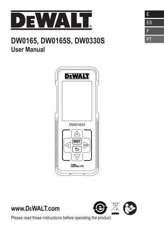
  • 1. Please read these instructions before operating the product. www.DEWALT.com E NL GR PT FIN HU BG LV ES DK CZ E NO SK RO LT F SE RU PT PL SI EE TR HR DW0165, DW0165S, DW0330S User Manual DW0165S
  • 2. 1 2 0.000 m 0.000 m 0.000 m 0.000 m 50.0° DW0165S B D AAAA A A AAA AAA AAA 2 Figures A 4 DW0165 4.5V DC 2 5 6 1 3 7 8 C 3 1 2 4 5 6 0.0000 m 0.0000 m 0.0000 m 0.0000 m 50.0°
  • 3. 50.0° 0.0000 m 0.0000 m 0.0000 m 0.0000 m 50.0° = = = = ft/m
  • 4. 4 Figures H J K 0.0000 m 0.0000 m 0.0000 m 0.7000m 50.0° I 71.77 in 45.86 in 45.86 in 50.0° max min + 0.3000 m 0.7000 m 1.0000m 50.0° + - / 0.8500m - 50.0° 0.1500 m 1.0000 m + - /
  • 5. 5 L 0.6000 m 0.4000 m 0.2400 m 50.0° 2 M N O 0.7000 m 0.6000 m 0.5000 m 0.2100m 50.0° 3 2 0.240 m 2 + 0.210 m 0.450 m 2 50.0° + - / +/- +/-
  • 8. 8 Figures 12” 12” 12” 0.000 in 0.00 in 12.0 in 50.0° a a 12” 12” 0.000 in 12.0 in 12.0 in 50.0° a a 12” 12” 0.000 in 12.0 in 12.0 in 50.0° a a 12” U
  • 10. 10 E Contents • User Safety • Battery Safety • Loading Batteries • Turning the Tool On • Choosing the Settings • Taking Measurements • Calibrating the Tool • Warranty • Specifications • Error Codes Retain all sections of this manual for future reference. User Safety WARNING: Carefully read the Safety Instructions and Product Manual before using this product. The person responsible for the product must ensure that all users understand and adhere to these instructions. WARNING: The following label information is placed on your laser tool to inform you of the laser class for your convenience and safety. DW0165 4.5V DC DW0165S FCC ID: 2ANWF-DW0165 IC: 23237-DW0165 4.5V DC The DW0165/DW0165S/DW0330S tool emits a visible laser beam, as shown in Figure A 1 . The laser beam emitted is Laser Class 2 per IEC 60825-1 and complies with 21 CFR 1040.10 and 1040.11 except for deviations pursuant to Laser Notice No. 50, dated June 24, 2007. WARNING: While the laser tool is in operation, be careful not to expose your eyes to the emitting laser beam (red light source). Exposure to a laser beam for an extended time period may be hazardous to your eyes. Do not look into the beam with optical aids. WARNING: To reduce the risk of injury, user must read the Product User manual, Laser Safety manual, and Battery Safety information. FCC Compliance This device complies with Part 15 of the FCC Rules. Operation is subject to the following two conditions: (1) This device may not cause harmful interference, and (2) this device must accept any interference received, including interference that may cause undesired operation. FCC Statement This equipment has been tested and found to comply with the limits for a Class B digital device, pursuant to part 15 of the FCC rules. These limits are designed to provide reasonable protection against harmful interference in a residential installation. This equipment generates, uses, and can radiate radio frequency energy and, if not installed and used in accordance with the instructions, may cause harmful interference to radio communications. This device is a portable unit. The exclusion threshold is 0.8873. However, there is no guarantee that interference will not occur in a particular installation. If this equipment does cause harmful interference to radio or television reception, which can be determined by turning the equipment off and on, the user is encouraged to try to correct the interference by one or more of the following measures: - Reorient or relocate the receiving antenna. - Increase the separation between the equipment and the receiver. - Connect the equipment into an outlet on a different circuit (not the circuit to which the receiver is connected). DW0330S FCC ID: 2ANWFDW0330 IC: 23237-DW0330 4.5V DC
  • 11. 11 E - Consult the dealer or an experienced radio/TV technician for help. Canada, Industry Canada (IC) Notices Class B digital circuitry of this device complies with Canadian ICES-003. This device complies with Industry Canada license-exempt RSS standard(s). Operation is subject to the following two conditions: (1) this device may not cause interference, and (2) this device must accept any interference, including interference that may cause undesired operation of the device. Under Industry Canada regulations, the radio transmitter(s) in this device may only operate using an antenna of a type and maximum (or lesser) gain approved for the transmitter by Industry Canada. To reduce potential radio interference to other users, the antenna type and its gain should be so chosen that the equivalent isotropically radiated power (e.i.r.p.) is not more than that necessary for successful communication. Battery Safety WARNING: Batteries can explode or leak and cause serious injury or fire. To reduce the risk: ALWAYS follow all instructions and warnings on the battery label and package. DO NOT short any battery terminals. DO NOT charge alkaline batteries. DO NOT mix old and new batteries. Replace all of them at the same time with new batteries of the same brand and type. DO NOT mix battery chemistries. DO NOT dispose of batteries in fire. ALWAYS keep batteries out of reach of children. ALWAYS remove batteries if the device will not be used for several months. NOTE: Ensure that the recommended batteries are used. NOTE: Ensure the batteries are inserted in the correct manner, with the correct polarity. Loading Batteries 1. Pull up the endpiece on the back of the tool (Figure D 1 ). 2. Pull up the battery compartment latch on the back of the tool (Figure D 2 and D 3 ). 3. Insert three AAA batteries, making sure to position the - and + ends of each battery as noted inside the battery compartment (Figure D 4 ). 4. Push the battery door down until it snaps in place (Figure D 5 ). When the tool is ON, the battery level appears on the screen (Figure C 1 ). Turning the Tool On 1. Point the tool's laser (Figure A 1 ) toward a wall or object, and not toward anyone's eyes. 2. Press (Figure A 3 ) to turn the tool on and display the red laser dot. Choosing the Settings Setting Automatic Turn Off By default, the tool will automatically turn off 90 seconds after no buttons or options have been selected. To change when the tool automatically turns off, follow these steps. 1. On the first screen (Figure E 1 ), press to display the Main Menu. 2. On the Main Menu (Figure E 2 ), select and press . 3. On the Settings Menu (Figure G ), select and press . 4. Select the time. • Choose to turn off the tool after 30 sec, 60 secs, 90 secs, or 300 secs. • To keep the tool turned on until you manually turn it off (by pressing and holding for 10 seconds), select ∞. 5. Press to save your setting.
  • 12. 12 E Setting Screen Brightness By default, the tool's screen will be set at 25% brightness. To change the brightness level, follow these steps. 1. On the first screen (Figure E 1 ), press to display the Main Menu. 2. On the Main Menu (Figure E 2 ), select and press . 3. On the Settings Menu (Figure G ), select and press . 4. Select the desired brightness level: 25%, 50%, 75%, or 100%. 5. Press to save your new setting. Turning Off the Sound By default, the tool will beep each time you take a measurement. You can turn off the beeps. 1. On the first screen (Figure E 1 ), press to display the Main Menu. 2. On the Main Menu (Figure E 2 ), select and press . 3. On the Settings Menu (Figure G ), select and press to display . 4. Press to save your setting. Changing the Unit of Measure ft/m By default, the tool will display measurements in inches (74 9/16 in). You can change the unit of measure to fractional ft (6'029/16), meters (1.8940 m), decimal ft (6.21 ft), or decimal inches (3.21 in). 1. On the first screen (Figure E 1 ), press to display the Main Menu. 2. On the Main Menu (Figure E 2 ), select and press . 3. On the Settings Menu (Figure G ), select ft/m and press . 4. Select the unit of measure. • 0'00 0/00 • 0 0/00 • 0'00 ft • 0.00 in • 0.0000 m 5. Press to save your setting. Choosing the Tool Position By default, distances are measured from the bottom of the tool to a wall or object (Figure F 3 ). To measure distances from a different tool location, follow these steps. 1. On the first screen (Figure E 1 ), press to display the Main Menu. 2. On the Main Menu (Figure E 2 ), select and press . 3. Select the tool position. • To measure from the top of the tool (Figure F 1 ), select . • To measure from the tripod connection on the tool (Figure F 2 ), select . • To measure from a corner or another hard-to- reach location with the endpiece flipped open (Figure D 1 ), select (Figure F 4 ) to measure from the end of the endpiece. 4. Press to save your new setting. Taking Measurements Measuring Distance 1. Point the tool's laser (Figure A 1 ) toward a wall or object, and not toward anyone's eyes. 2. Press (Figure A 3 ) to turn the tool on and display the red laser dot. 3. Make sure the tool position setting (Figure C 4 ) is correct for taking the measurement. 4. Point the tool's laser (Figure A 1 ) toward the wall or object whose distance you need to measure (Figure H 1 ).
  • 13. 13 E 5. Press to measure the distance from the tool to the wall or object. 6. At the bottom of the screen, view the current measurement (Figure H 2 ). To take a new measurement, press to move the current measurement up to the previous line on the screen. Then repeat steps 4-6. Adding 2 Measurements You can add two measurements to get a total measurement of the two distances (Figure I ). 1. Point the tool's laser (Figure A 1 ) toward a wall or object, and not toward anyone's eyes. 2. Press (Figure A 3 ) to turn the tool on and display the red laser dot. 3. Make sure the tool position setting (Figure C 4 ) is correct for taking the measurement. 4. Select as the measurement type. • Press to display the Main Menu (Figure E 2 ) • Press to select . • Press to display the Measurement Type Menu (Figure E 3 ). • Press the arrow buttons to select . • Press . 5. Press to indicate that you want to add two measurements. 6. Point the tool's laser toward the wall or object whose distance you need to measure (Figure I 1 ). 7. Press to measure the distance from the tool to the first wall or object. 8. Point the tool's laser toward the next wall or object (Figure I 2 ). 9. Press to measure the distance and add it to the previous measurement. 10. View the total of the two measurements at the bottom of the screen (Figure I 3 ). Subtracting 2 Measurements You can subtract one measurement from another (Figure J ). 1. Point the tool's laser (Figure A 1 ) toward a wall or object, and not toward anyone's eyes. 2. Press (Figure A 3 ) to turn the tool on and display the red laser dot. 3. Make sure the tool position setting (Figure C 4 ) is correct for taking the measurement. 4. Select as the measurement type. • Press to display the Main Menu (Figure E 2 ). • Press to select . • Press to display the Measurement Type Menu (Figure E 3 ). • Press the arrow buttons to select . • Press . 5. Press to indicate that you want to subtract one measurement from another. 6. Point the tool's laser toward the wall or object whose distance you need to measure (Figure J 1 ). 7. Press to measure the distance from the tool to the wall or object. 8. Point the tool's laser toward the wall or object whose distance is to be subtracted from the first measurement (Figure J 2 ). 9. Press to measure the distance and subtract it from the previous measurement. 10. View the difference between the two measurements at the bottom of the screen (Figure J 3 ).
  • 14. 14 E Measuring Continuously To take a series of measurements as you move around, change to Continuous Measure mode (Figure K ). 1. Point the tool's laser (Figure A 1 ) toward a wall or object, and not toward anyone's eyes. 2. Press Figure A 3 ) to turn the tool on and display the red laser dot. 3. Make sure the tool position setting (Figure C 4 ) is correct for taking the measurement. 4. Select as the measurement type. • Press to display the Main Menu (Figure E 2 ). • Press to select . • Press to display the Measurement Type Menu (Figure E 3 ). • Press the arrow buttons to select . • Press . 5. Point the tool's laser (Figure A 1 ) toward the wall or object whose distance you need to measure (Figure K 1 ). 6. At the bottom of the screen, view the current measurement (Figure K 2 ), which will keep changing as you move the tool. 7. To take the current measurement (from the tool to the wall or object) and exit Continuous Measure mode, press . To take a new measurement, press to move the current measurement up to the previous line on the screen. Then repeat steps 4-7. Measuring Area You can measure the area of a wall, floor, or object (Figure L ). 1. Point the tool's laser (Figure A 1 ) toward a wall or object, and not toward anyone's eyes. 2. Press (Figure A 3 ) to turn the tool on and display the red laser dot. 3. Make sure the tool position setting (Figure C 4 ) is correct for taking the measurement. 4. Select as the measurement type. • Press to display the Main Menu (Figure E 2 ). • Press to select . • Press to display the Measurement Type Menu (Figure E 3 ). • Press the arrow buttons to select . • Press . 5. Measure the width (Figure L 1 ). • Point the top of the tool at one side of the wall, floor, or object. • Position the tool at one end of the wall, floor, or object and point the laser dot across the width. (Figure L 1 shows where to position the tool if you are measuring from the bottom of the tool.) • Press to display the width measurement at the top of the screen. 6. Measure the length (Figure L 2 ). • Position the tool at one end of the wall, floor, or object and point the laser dot across the length. (Figure L 2 shows where to position the tool if you are measuring from the bottom of the tool.) • Press to display the length measurement on the second line of the screen. 7. View the Area measurement at the bottom of the screen (Figure L 3 ). Adding/Subtracting 2 Areas You can measure the area of a wall, floor, or object and then add it to, or subtract it from, the area of another wall, floor, or object (Figure M ). 1. Point the tool's laser (Figure A 1 ) toward a wall or object, and not toward anyone's eyes. 2. Press (Figure A 3 ) to turn the tool on and display the red laser dot. 3. Make sure the tool position setting (Figure C 4 ) is correct for taking the measurement.
  • 15. 15 E 4. Select as the measurement type. • Press to display the Main Menu (Figure E 2 ). • Press to select . • Press to display the Measurement Type Menu (Figure E 3 ). • Press the arrow buttons to select . • Press . 5. Press to add, or to subtract, the areas of two walls, floors, or objects. 6. Measure the width of the first wall, floor, or object (Figure M 1 ). • Position the tool at one end of the wall, floor, or object and point the laser dot across the width. (Figure M 1 shows where to position the tool if you are measuring from the bottom of the tool.) • Press to display the width measurement at the top of the screen. 7. Measure the length of the first wall, floor, or object (Figure M 2 ). • Position the tool at one end of the wall, floor, or object and point the laser dot across the length. (Figure M 2 shows where to position the tool if you are measuring from the bottom of the tool.) • Press to display the length measurement on the second line of the screen. 8. Follow the same steps to measure the width and length of the second wall, floor, or object. 9. View the Area measurement at the bottom of the screen (Figure M 3 ). Measuring Volume You can measure the volume of a room or object (Figure N ). 1. Point the tool's laser (Figure A 1 ) toward a wall or object, and not toward anyone's eyes. 2. Press (Figure A 3 ) to turn the tool on. 3. Make sure the tool position setting (Figure C 4 ) is correct for taking the measurement. 4. Select as the measurement type. • Press to display the Main Menu (Figure E 2 ). • Press to select . • Press to display the Measurement Type Menu (Figure E 3 ). • Press the arrow buttons to select . • Press . 5. Measure the width (Figure N 1 ). • Point the top of the tool at one side of the target (room or object). • Position the tool at one end of the target and point the laser dot across the width. (Figure N 1 shows where to position the tool if you are measuring from the bottom of the tool.) • Press to display the width measurement at the top of the screen. 6. Measure the length (Figure N 2 ). • Position the tool at one end of the target and point the laser dot across the length. (Figure N 2 shows where to position the tool if you are measuring from the bottom of the tool.) • Press to display the length measurement on the second line of the screen. 7 Measure the height (Figure N 3 ). • Position the tool at one end of the target and point the laser dot across the height. (Figure N 3 shows where to position the tool if you are measuring from the bottom of the tool). • Press to display the height measurement on the third line of the screen. 8. View the Volume measurement at the bottom of the screen (Figure N 4 ).
  • 16. 16 E Adding/Subtracting 2 Volumes You can measure the volume of room or object and then add it to, or subtract it from, the volume of another room or object (Figure O ). 1. Point the tool's laser (Figure A 1 ) toward a wall or object, and not toward anyone's eyes. 2. Press (Figure A 3 ) to turn the tool on and display the red laser dot. 3. Make sure the tool position setting (Figure C 4 ) is correct for taking the measurement. 4. Select as the measurement type. • Press to display the Main Menu (Figure E 2 ). • Press to select . • Press to display the Measurement Type Menu (Figure E 3 ). • Press the arrow buttons to select . • Press . 5. Press to add, or to subtract, the volumes of two rooms or objects. 6. Measure the width (Figure O 1 ). • Position the tool at one end of the room or object and point the laser dot across the width. (Figure O 1 shows where to position the tool if you are measuring from the bottom of the tool.) • Press to display the width measurement at the top of the screen. 7. Measure the length (Figure O 2 ). • Position the tool at one end of the room or object and point the laser dot across the length. (Figure O 2 shows where to position the tool if you are measuring from the bottom of the tool.) • Press to display the length measurement on the second line of the screen. 8. Measure the height (Figure O 3 ). • Position the tool at one end of the room or object and point the laser dot across the height. (Figure O 3 shows where to position the tool if you are measuring from the bottom of the tool). • Press to display the height measurement on the third line of the screen. 9. Follow the same steps to measure the width, length, and height of the second room or object. 10. View the Volume measurement at the bottom of the screen (Figure O 4 ). Measuring the Height of a Tall Object If you need to measure the height of a tall object (e.g., a tall building), you can calculate the height based on the distance to 1 point or the distances from the same point to 2 points on the object. The tool will use the Pythagorean Theorem (C2 =A2 +B2 ) to calculate the height. Distance to 1 Point You can use the distance to one point on a wall or object (Indirect Height) to determine its height (Figure P ). 1. Point the tool's laser (Figure A 1 ) toward a wall or object, and not toward anyone's eyes. 2. Press (Figure A 3 ) to turn the tool on and display the red laser dot. 3. Make sure the tool position setting (Figure C 4 ) is correct for taking the measurement. 4. Select as the measurement type. • Press to display the Main Menu (Figure E 2 ). • Press to select . • Press to display the Measurement Type Menu (Figure E 3 ). • Press the arrow buttons to select . • Press . 5. Position the tool opposite the bottom of the vertical height to be measured (Figure P 1 ).
  • 17. 17 E 6. Point the laser toward the highest point of the building or object whose height you need to measure (Figure P 1 ). 7. Press to measure the distance. 8. View the height measurement at the bottom of the screen (Figure P 2 ). Distances to 2 Points You can use the distance to two points on a wall or object (Double Indirect Height) to determine its height (Figure Q ). 1. Point the tool's laser (Figure A 1 ) toward a wall or object, and not toward anyone's eyes. 2. Press (Figure A 3 ) to turn the tool on and display the red laser dot. 3. Make sure the tool position setting (Figure C 4 ) is correct for taking the measurement. 4. Select as the measurement type. • Press to display the Main Menu (Figure E 2 ). • Press to select . • Press to display the Measurement Type Menu (Figure E 3 ). • Press the arrow buttons to select . • Press . 5. Position the tool opposite the approximate center of the vertical height to be measured (Figure Q 1 ). 6. Point the laser toward the lowest point of the building or object whose height you need to measure (Figure Q 2 ). 7. Press to measure the distance. 8. From the same point, aim the laser at the highest point of the building or object (Figure Q 3 ). 9. Press to measure the distance. 10. On the bottom line of the screen, view the height of the building or object (Figure Q 4 ). Measuring Partial Height of a Wall If you need to determine the height of a section of a wall or object (e.g., the distance from the ceiling to the top of TV or window on the wall) (Figure R ). 1. Point the tool's laser (Figure A 1 ) toward a wall or object, and not toward anyone's eyes. 2. Press (Figure A 3 ) to turn the tool on and display the red laser dot. 3. Make sure the tool position setting (Figure C 4 ) is correct for taking the measurement. 4. Select as the measurement type. • Press to display the Main Menu (Figure E 2 ). • Press to select . • Press to display the Measurement Type Menu (Figure E 3 ). • Press the arrow buttons to select . • Press . 5. Point the laser at the highest point of the wall or object (Figure R 1 ). 6. Press to measure the distance to the top of the tall object. 7. From the same point, aim the laser at the top of the obstruction on the wall or object (Figure R 2 ). 8. Press to measure the distance from the top of the wall to the obstruction (TV, window, etc.). 9. From the same point, aim the laser on a horizontal line straight ahead toward the bottom of the wall (Figure R 3 ). 10. Press to measure the distance. 11. On the bottom line of the screen, view the distance between the top of the wall and the top of the obstruction on the wall (Figure R 4 ).
  • 18. 18 E Measuring Height of Obstructed Object - Follow these steps to determine the height of a tall building or object that is blocked by other buildings or objects (Figure S ). 1. Point the tool's laser (Figure A 1 ) toward a wall or object, and not toward anyone's eyes. 2. Press (Figure A 3 ) to turn the tool on and display the red laser dot. 3. Make sure the tool position setting (Figure C 4 ) is correct for taking the measurement. 4. Select as the measurement type. • Press to display the Main Menu (Figure E 2 ). • Press to select . • Press to display the Measurement Type Menu (Figure E 3 ). • Press the arrow buttons to select (Figure E 4 ). • Press . 5. Point the laser at the highest point of the building, wall, or object (Figure S 1 ). 6. Press to take the measurement. 7. On the bottom line of the screen, view the height of the building or object (Figure S 2 ). Measuring from a Tripod If you are placing the tool on a tripod to measure the height of a tall building, follow these steps (Figure T ). 1. Screw the 1/4-20 hole on the back of the tool onto the 1/4-20 connection on the top of your tripod (Figure T 1 ). 2. Point the tool's laser (Figure A 1 ) toward a wall or object, and not toward anyone's eyes. 3. Press (Figure A 3 ) to turn the tool on and display the red laser dot. 4. Make sure the tool position setting (Figure C 4 ) is to measure from the tripod connection. 5. Select as the measurement type. • Press to display the Main Menu (Figure E 2 ). • Press to select . • Press to display the Measurement Type Menu (Figure E 3 ). • Press the arrow buttons to select (Figure E 4 ). • Press . 6. Point the laser at the lowest point of the wall or object whose height you need to measure (Figure T 2 ). 7. Press to take the measurement. 8. Point the laser at other points on the wall or object (Figure T 3 ). 9. When ready, press to take the measurement. 10. On the bottom line of the screen, view the height of the wall or object (Figure T 4 ). Positioning Studs a a When you are framing a wall, use the Stakeout feature to easily mark the position of each stud (Figure U ). 1. Point the tool's laser (Figure A 1 ) toward a wall or object, and not toward anyone's eyes. 2. Press (Figure A 3 ) to turn the tool on and display the red laser dot. 3. Make sure the tool position setting (Figure C 4 ) is set to to measure from the back of the tool. 4. Select a a as the measurement type. • Press to display the Main Menu (Figure E 2 ). • Press to select . • Press to display the Measurement Type Menu (Figure E 3 ). • Press the arrow buttons to select a a (Figure E 4 ). • Press .
  • 19. 19 E 5. Determine the distance between each stud, for example, 12. 6. Press and until the top number on the screen is set to the distance from the right edge of one stud to the left edge of the next (e.g., 12) (Figure U 1 ). 7. Line up the back of the tool with the right edge of the last stud that is nailed in (Figure U 2 ). 8. Press to start measuring the distance as you slowly move the tool to the right. 9. Continue moving the tool to the right until the bottom number on the screen is 0.00 in (Figure U 3 ). 10. Press to stop measuring. 11. Using a pencil, mark the location where the left edge of the stud should be nailed into the wall frame. 12. Nail the left edge of the stud at the marked location. 13. For each remaining stud in the wall frame, repeat steps 7-12 (Figure U 4 ). Measuring an Angle If you need to determine the angle at which something is positioned, use the tool to measure that angle (Figure W ). 1. Point the tool's laser (Figure A 1 ) toward a wall or object, and not toward anyone's eyes. 2. Press (Figure A 3 ) to turn the tool on and display the red laser dot. 3. Make sure the tool position setting (Figure C 4 ) is correct for taking the measurement. 4. Select as the measurement type. • Press to display the Main Menu (Figure E 2 ). • Press to select . • Press to display the Measurement Type Menu (Figure E 3 ). • Press the arrow buttons to select . • Press . 5. Position the tool at the angle to be measured (Figure W 1 ). 6. Press to take the measurement. 7. View the angle measurement on the screen (Figure W 2 ). Using the Tool as a Level 1. Point the tool's laser (Figure A 1 ) toward a wall or object, and not toward anyone's eyes. 2. Press (Figure A 3 ) to turn the tool on and display the red laser dot. 3. Select as the measurement type. • Press to display the Main Menu (Figure E 2 ). • Press to select . • Press to display the Measurement Type Menu (Figure E 3 ). • Press the arrow buttons to select . • Press . 4. Place the tool in the vertical or horizontal position on the surface that you want to check is level (Figure V 1 ). 5. On the tool's screen, view the position of the white bubble on the vial (Figure V 2 ).
  • 20. 20 E Using DW0165S/DW0330S With If you have a DW0165S or DW0330S, you can use its Bluetooth® capability to pair it with the DEWALT® Tool Connect™ application on your cell phone or tablet, and then mark up room photos with the measurements you have taken. 1. From either or , download the DEWALT® Tool Connect™ application to your cell phone or tablet. 2. Using the DEWALT® Tool Connect™ application, capture the room or space for which you want to record the measurements, by taking room photos. 3. On the DW0165S or DW0330S keypad, press to turn on the tool. 4. If appears on the screen (Figure C 2 ), turn on the Bluetooth® connection. • On the keypad, press to display the main menu. • Select . • Press to turn on the Bluetooth® connection. 5. Use the DEWALT® Tool Connect™ application to pair your cell phone or tablet to the DW0165S or DW0330S, and then mark up room photos with the measurements you have taken. THE BLUETOOTH® WORD MARK AND LOGOS ARE REGISTERED TRADEMARKS OWNED BY BLUETOOTH SIG, INC. AND ANY USE OF SUCH MARKS BY DEWALT IS UNDER LICENSE. APPLE AND THE APPLE LOGO ARE TRADEMARKS OF APPLE INC., REGISTERED IN THE U.S. AND OTHER COUNTRIES. APP STORE IS A SERVICE MARK OF APPLE INC., REGISTERED IN THE U.S. AND OTHER COUNTRIES. GOOGLE PLAY AND THE GOOGLE PLAY LOGO ARE TRADE- MARKS OF GOOGLE INC. Viewing the Tool's Memory Up to the last 20 measurements are stored in the tool's memory. 1. Point the tool's laser (Figure A 1 ) toward a wall or object, and not toward anyone's eyes. 2. Press (Figure A 3 ) to turn the tool on and display the red laser dot. 3. Select as the measurement type. • Press to display the Main Menu (Figure E 2 ). • Press to select . • Press to display the Measurement Type Menu (Figure E 3 ). • Press the arrow buttons to select (Figure E 4 ). • Press . 4. View the last measurement that was taken. Press to scroll through all the measurements that have been stored in the tool's memory (up to 20). Press to scroll back. Clearing the Tool's Memory You can clear one or more measurements that are currently in the tool's memory. Clearing a Measurement 1. Point the tool's laser (Figure A 1 ) toward a wall or object, and not toward anyone's eyes. 2. Press (Figure A 3 ) to turn the tool on and display the red laser dot. 3. Select as the measurement type. • Press to display the Main Menu (Figure E 2 ). • Press to select . • Press to display the Measurement Type Menu (Figure E 3 ). • Press the arrow buttons to select (Figure E 4 ). • Press . 4. Specify which measurement you want to delete: • To delete a specific measurement, continue with step 5. • To delete ALL measurements, skip to step 6. 5. To delete a specific measurement: • Press or to scroll through the measurements that have been stored in the tool's memory (up to 20) until you display the
  • 21. 21 E measurement to be deleted. • Press . • Select and press to delete the measurement. 6. To delete ALL measurements: • Press . • Select and press to delete all measurements from the tool's memory. Turning Off the Tool The tool can be turned off in either of these ways: • Press and hold for 10 seconds. When you release after 10 seconds, the tool will turn off. • If you do not use the tool for 90 seconds, it will automatically turn off. Calibrating the tool Please note that if you do not position the tool correctly for each step of the calibration process, will appear in red on the screen (Figure X ). 1. Point the tool's laser (Figure A 1 ) toward a wall or object, and not toward anyone's eyes. 2. Press (Figure A 3 ) to turn the tool on and display the red laser dot. 3. Press to display the Main Menu (Figure E 2 ). 4. On the Main Menu, select and press . 5. On the Settings Menu (Figure G ), select and press . 6. Place the tool with the screen facing upward on a flat, level surface (Figure X 1 ). 7. Press . 8. While the tool is still laying on the level surface, turn the tool 180° (Figure X 2 ). 9. Press . 10. Flip the long side of the tool 90° so it is laying on its side (Figure X 3 ). 11. Press . 12. While the tool is still laying on its side, turn the tool 180° (Figure X 4 ). 13. Press . 14. Make sure appears on the tool's screen (Figure X 5 ). Three Year Limited Warranty DEWALT will repair, without charge, any defects due to faulty materials or workmanship for three years from the date of purchase. This warranty does not cover part failure due to normal wear or tool abuse. For further detail of warranty coverage and warranty repair information, visit www.DEWALT.com or call 1–800–4-DEWALT (1–800–433–9258). This warranty does not apply to accessories or damage caused where repairs have been made or attempted by others. This warranty gives you specific legal rights and you may have other rights which vary in certain states or provinces. In addition to the warranty, DEWALT® tools are covered by our: 1 YEAR FREE SERVICE DEWALT will maintain the tool and replace worn parts caused by normal use, for free, any time during the first year after purchase. 90 DAY MONEY BACK GUARANTEE If you are not completely satisfied with the performance of your DEWALT Power Tool, Laser, or Nailer for any reason, you can return it within 90 days from the date of purchase with a receipt for a full refund - no questions asked. RECONDITIONED PRODUCT: Reconditioned product is covered under the 1 Year Free Service Warranty. The 90 Day Money Back Guarantee and the Three Year Limited Warranty do not apply to reconditioned product. FREE WARNING LABEL REPLACEMENT: If your warning labels become illegible or are missing, call 1-800-4-DEWALT or visit your local service center for a free replacement.
  • 22. 22 E Specifications DW0165 DW0165S DW0330S Range 6in to 165ft (0.15m to 50m) 6in to 330ft (0.15m to 100m) Measuring Accuracy1 up to 10m: 1/16in (1.5mm) 10m-30m: 0.078in/5/64in) additional (+/- 0.15mm/m) 30m: +/- 0.002in/ft (+/- 0.2mm/m) Resolution2 1/16in (1mm) Laser Class Class 2 (IEC/EN60825-1: 2014) Laser Type ≤ 1.0mW @ 630-680nm Laser Automatic Switch-off 30s Unit Automatic Switch-off By default, 90s. User can set to 30s, 60s, or 300s Continuous Measuring Yes Area Yes Volume Yes Pythagoras 2-Point Yes Endpiece to measure from corners 3 Yes Battery Life (3 x AAA) Up to 3000 Measurements (2500 with ; DW0165S DW0330S) Dimension (H x D x W) 4.72 x 1.91 x 1.02in (120 x 48.5 x 26mm) Weight (with Batteries) 9.88oz (280g) Storage Temperature Range 14° F ~ 140° F (-10° C ~ +60 C) Operating Temperature Range 32° F ~ 104° F (0° C ~ +40° C) 1 Measuring Accuracy depends on the current conditions: • Under favorable conditions (good target surface and room temperature), up to 33ft (10m). • Under unfavorable conditions (bright sunlight, a very weak reflecting target surface, or large temperature fluctuations), the error can increase by to ± 0.003 in/ft (± 0.25mm/m) for distances over 33ft (10m). 2 Resolution is the finest measurement you can see. In inches, that is 1/16. In mm, that is 1mm. 3 Flip open the endpiece at the bottom of the tool when you need to fit the tool into corners or grooves that are not at 180° angles. If a corner is at 90°, the endpiece can be used to hold the tool up against something.
  • 23. Error Codes If INFO appears on the screen with a Code number, perform the corresponding Corrective Action. Code Description Corrective Action 101 Received Signal Too Weak, Measuring Time Too Long Use the target plate or change the target surface. 102 Received Signal Too High Target is too reflective. Use the target plate or change the target surface. 201 Too Much Background Light Reduce the background light on the target area. 202 Laser Beam Interrupted Remove the obstacle and repeat the measurement. 301 Temperature Too High Allow the device to cool down to a temperature within the specified Operating Temperature Range. 302 Temperature Too Low Allow the device to warm up to a temperature within the specified Operating Temperature Range. 401 Hardware Error Switch the device on/off several times. If the error still occurs, return the defective device to the Service Center or distributor. Refer to the Warranty. 402 Unknown Error Contact the Service Center or distributor. Refer to the Warranty. 500 Data Error Contact the Service Center or distributor. Refer to the Warranty.
  • 24. ES 24 Contenido • Seguridad del usuario • Seguridad de la batería • Carga de baterías • Encendido de la herramienta • Elección de los ajustes • Toma de mediciones • Calibración de la herramienta • Garantía • Especificaciones • Códigos de error Conserve todas las secciones de este manual para futura referencia. Seguridad del usuario ADVERTENCIA: Lea con atención las instrucciones de seguridad y el manual del producto antes de usar el producto. La persona responsable del producto debe asegurarse que todos los usuarios entiendan y cumplan con estas instrucciones. ADVERTENCIA: La siguiente etiqueta de información se coloca en su herramienta láser para informarle sobre la clase de láser para su comodidad y seguridad. DW0165 4.5V DC DW0165S FCC ID: 2ANWF-DW0165 IC: 23237-DW0165 4.5V DC La herramienta DW0165/DW0165S/ DW0330S emite un rayo láser visible, como se muestra en la Figura A 1 . El rayo láser emitido es un Láser Clase 2 en conformidad con la norma IEC 60825-1 y cumple las normas 21 CFR 1040.10 y 1040.11, excepto en las desviaciones en conformidad con lo establecido en Laser Notice No. 50, del 24 de junio de 2007. ADVERTENCIA: Mientras la herramienta láser esté en uso, tenga cuidado de no exponer sus ojos al rayo láser (fuente de luz roja). La exposición a un rayo láser durante un largo periodo de tiempo podría ser peligroso para sus ojos. No mire directamente al rayo con ayudas ópticas. ADVERTENCIA: Para reducir el riesgo de lesiones, el usuario debe leer el manual de usuario del producto, el manual de seguridad del láser y la información de seguridad de la batería. Conformidad con FCC Este dispositivo cumple con la Parte 15 del Reglamento FCC. La operación está sujeta a las dos condiciones siguientes: (1) Este dispositivo puede no causar interferencia dañina, y (2) este dispositivo debe aceptar cualquier interferencia recibida, incluso las interferencias que pudieran causar operación no deseada. Declaración de FCC Este equipo ha sido probado y cumple con los límites para dispositivos digitales de clase B, de conformidad con la parte 15 de las normas FCC. Estos límites han sido diseñados para proporcionar una protección razonable contra las interferencias nocivas en instalaciones residenciales. Este equipo genera, usa e irradia energía de radiofrecuencia y, si no se instala y se usa de acuerdo con las instrucciones, puede causar interferencia perjudicial para las radiocomunicaciones. Este dispositivo es una unidad portátil. El umbral de exclusión es de 0.8873. No obstante, no existe ninguna garantía de que no se producirá interferencia en una instalación determinada. Si este equipo causa interferencias perjudiciales para la recepción de radio o televisión, que puede determinarse al encender y apagar el equipo, el usuario puede tratar de corregir la interferencia tomando una o varias de las siguientes medidas: DW0330S FCC ID: 2ANWFDW0330 IC: 23237-DW0330 4.5V DC
  • 25. 25 ES - Reorientar o reubicar la antena receptora. - Aumentar la distancia entre el equipo y el receptor. - Conectar el equipo en un tomacorriente de otro circuito diferente (no el circuito al que está conectado el receptor). - Consulte al vendedor o a un técnico experto en radio/TV para solicitar su ayuda. Canadá, Avisos del Ministerio de la Industria de Canadá (IC) Los circuitos digitales de clase B de este dispositivo cumplen con la norma canadiense ICES-003. Este dispositivo cumple las normas RSS de exención de licencia del Ministerio de la Industria de Canadá. La operación está sujeta a las dos condiciones siguientes: (1) este dispositivo puede no causar ninguna interferencia nociva, y (2) este dispositivo debe aceptar cualquier interferencia, incluso las interferencias que pudieran causar una operación no deseada del dispositivo. De conformidad con las disposiciones del Ministerio de la Industria de Canadá, el o los radiotransmisores de este dispositivo sólo pueden funcionar usando una antena de un tipo y una ganancia máxima (o inferior) aprobados para el transmisor por el Ministerio de la Industria de Canadá. Para reducir la potencial interferencia de radio a otros usuarios, el tipo de antena y la ganancia deben ser elegidas para que la potencia radiada isotrópica equivalente (p.i.r.e.) no sea superior a la necesaria para una comunicación correcta. Seguridad de la batería ADVERTENCIA: Las baterías pueden explotar o tener fugas y causar lesiones personales o incendios. Para reducir el riesgo: SIEMPRE siga todas las instrucciones y las advertencias colocadas en las etiquetas y el paquete de las baterías. NO ponga en corto circuito las terminales de la batería. NO cargue las baterías alcalinas. NO mezcle baterías nuevas y viejas. Cambie todas las baterías a la vez con baterías nuevas del mismo tipo y marca. NO mezcle la química de las baterías. NO deseche las baterías en fuego. SIEMPRE mantenga las baterías fuera del alcance de los niños. SIEMPRE retire las baterías si el dispositivo no va a utilizarse durante varios meses. NOTA: Asegúrese de utilizar las baterías recomendadas. NOTA: Asegúrese de insertar las baterías de manera correcta, respetando la polaridad. Carga de baterías 1. Jale hacia arriba la pieza de extremo en la parte trasera de la herramienta (Figura D 1 ). 2. Jale hacia arriba el seguro del compartimiento de la batería en la parte trasera de la herramienta (Figura D 2 y D 3 ). 3. Inserte tres baterías AAA, asegurándose de colocar los extremos - y + de cada batería como se indica dentro del compartimiento de la batería (Figura D 4 ). 4. Empuje la tapa de la batería hacia abajo hasta que se conecte en su lugar (Figura D 5 ). Cuando la herramienta esté ENCENDIDA, el nivel de batería aparece en la pantalla (Figura C 1 ). Encendido de la herramienta 1. Apunte el láser de la herramienta (Figura A 1 ) hacia una pared u objeto, y no a los ojos de nadie. 2. Presione (Figura A 3 ) para encender la herramienta y mostrar el punto láser rojo.
  • 26. ES 26 Elección de los ajustes Ajuste de apagado automático Por omisión, la herramienta se apaga automáticamente 90 segundos después de que no se haya seleccionado ningún botón u opciones. Para cambiar cuándo se apaga la herramienta automáticamente, siga estos pasos. 1. En la primer pantalla (Figura E 1 ), presione para mostrar el Menú principal. 2. En el Menú principal (Figura E 2 ), seleccione y presione . 3. En el Menú de configuración (Figura G ), seleccione y presione . 4. Seleccione la hora. • Elija para apagar la herramienta después de 30 seg., 60 seg., 90 seg., o 300 seg. • Para mantener la herramienta encendida hasta que la apague manualmente (presionando y sosteniendo por 10 segundos), seleccione ∞. 5. Presione para guardar sus ajustes. Ajuste de brillo de pantalla Por omisión, la pantalla de la herramienta se ajustará a 25% de brillo. Para cambiar el nivel de brillo, siga estos pasos. 1. En la primer pantalla (Figura E 1 ), presione para mostrar el Menú principal. 2. En el Menú principal (Figura E 2 ), seleccione y presione . 3. En el Menú de configuración (Figura G ), seleccione y presione . 4. Seleccione el nivel de brillo deseado: 25%, 50%, 75%, o 100%. 5. Presione para guardar su nuevo ajuste. Apagado de Sonido Por omisión, la herramienta hará un bip cada vez que tome una medición. Puede apagar los sonidos de bip. 1. En la primer pantalla (Figura E 1 ), presione para mostrar el Menú principal. 2. En el Menú principal (Figura E 2 ), seleccione y presione . 3. En el Menú de configuración (Figura G ), seleccione y presione para mostrar . 4. Presione para guardar sus ajustes. Cambio de unidad de medición ft/m Por omisión, la herramienta mostrará las mediciones en pulgadas (74 9/16 pulg.). Puede cambiar la unidad de medición a pies fraccionales (6'029/16), metros (1.8940 m), pies decimales (6.21 pies), o pulgadas decimales (3.21 pulg.). 1. En la primer pantalla (Figura E 1 ), presione para mostrar el Menú principal. 2. En el Menú principal (Figura E 2 ), seleccione y presione . 3. En el Menú de configuración (Figura G ), seleccione pies/m y presione . 4. Seleccione la unidad de medición. • 0'00 0/00 • 0 0/00 • 0'00 pies • 0.00 pulg. • 0.0000 m 5. Presione para guardar sus ajustes.
  • 27. 27 ES Elección de Posición de Herramienta Por omisión, las distancias se miden desde la parte inferior de la herramienta a una pared u objeto (Figura F 3 ). Para medir distancias desde una ubicación diferente de la herramienta, siga estos pasos. 1. En la primer pantalla (Figura E 1 ), presione para mostrar el Menú principal. 2. En el Menú principal (Figura E 2 ), seleccione y presione . 3. Seleccione la posición de la herramienta. • Para medir desde la parte superior de la herramienta (Figura F 1 ), seleccione . • Para medir desde la conexión del trípode en la herramienta (Figura F 2 ), seleccione . • Para medir desde una esquina u otra ubicación difícil de alcanzar con la pieza de extremo abierta (Figura D 1 ), seleccione (Figura F 4 ) para medir desde el extremo de la pieza de extremo. 4. Presione para guardar su nuevo ajuste. Toma de Mediciones Medición de Distancia 1. Apunte el láser de la herramienta (Figura A 1 ) hacia una pared u objeto, y no a los ojos de nadie. 2. Presione (Figura A 3 ) para encender la herramienta y mostrar el punto láser rojo. 3. Asegúrese que el ajuste de posición de la herramienta (Figura C 4 ) sea correcto para tomar la medición. 4. Apunte el láser de la herramienta (Figura A 1 ) hacia la pared u objeto para el que necesite medir la distancia (Figura H 1 ). 5. Presione para medir la distancia desde la herramienta a la pared u objeto. 6. En la parte inferior de la pantalla, vea la medición actual (Figura H 2 ). Para tomar una nueva medición, presione para mover la medición actual hasta la línea previa en la pantalla. Repita los pasos 4-6. Suma de 2 mediciones Puede sumar dos mediciones para obtener la medida total de dos distancias (Figura I ). 1. Apunte el láser de la herramienta (Figura A 1 ) hacia una pared u objeto, y no a los ojos de nadie. 2. Presione (Figura A 3 ) para encender la herramienta y mostrar el punto láser rojo. 3. Asegúrese que el ajuste de posición de la herramienta (Figura C 4 ) sea correcto para tomar la medición. 4. Seleccione como el tipo de medición. • Presione para mostrar el Menú principal (Figura E 2 ) • Presione para seleccionar . • Presione para mostrar el Menú de tipo de medición (Figura E 3 ). • Presione los botones de flecha para seleccionar . • Presione . 5. Presione para indicar que desea sumar dos mediciones. 6. Apunte el láser de la herramienta hacia la pared u objeto para el que desee medir la distancia (Figura I 1 ). 7. Presione para medir la distancia desde la herramienta a la primer pared u objeto. 8. Apunte el láser de la herramienta hacia la siguiente pared u objeto (Figura I 2 ). 9. Presione para medir la distancia y sumarla a la medición previa. 10. Vea el total de las dos mediciones en la parte inferior de la pantalla (Figura I 3 ).
  • 28. ES 28 Resta de 2 mediciones Puede restar una medición a partir de otra (Figura J ). 1. Apunte el láser de la herramienta (Figura A 1 ) hacia una pared u objeto, y no a los ojos de nadie. 2. Presione (Figura A 3 ) para encender la herramienta y mostrar el punto láser rojo. 3. Asegúrese que el ajuste de posición de la herramienta (Figura C 4 ) sea correcto para tomar la medición. 4. Seleccione como el tipo de medición. • Presione para mostrar el Menú principal (Figura E 2 ). • Presione para seleccionar . • Presione para mostrar el Menú de tipo de medición (Figura E 3 ). • Presione los botones de flecha para seleccionar . • Presione . 5. Presione para indicar que desea restar una medición a partir de otra. 6. Apunte el láser de la herramienta hacia la pared u objeto para el que desea medir la distancia (Figura J 1 ). 7. Presione para medir la distancia desde la herramienta a la pared u objeto. 8. Apunte el láser de la herramienta hacia la pared u objeto para el que se restará la distancia de la primera medición (Figura J 2 ). 9. Presione para medir la distancia y restarla a la medición previa. 10. Vea la diferencia entre las dos mediciones en la parte inferior de la pantalla (Figura J 3 ). Medición Continua Para tomar una serie de mediciones conforme se mueve, cambie a modo de Medición Continua (Figura K ). 1. Apunte el láser de la herramienta (Figura A 1 ) hacia una pared u objeto, y no a los ojos de nadie. 2. Presione Figura A 3 ) para encender la herramienta y mostrar el punto láser rojo. 3. Asegúrese que el ajuste de posición de la herramienta (Figura C 4 ) sea correcto para tomar la medición. 4. Seleccione como el tipo de medición. • Presione para mostrar el Menú principal (Figura E 2 ). • Presione para seleccionar . • Presione para mostrar el Menú de tipo de medición (Figura E 3 ). • Presione los botones de flecha para seleccionar . • Presione . 5. Apunte el láser de la herramienta (Figura A 1 ) hacia la pared u objeto para el que necesite medir la distancia (Figura K 1 ). 6. En la parte inferior de la pantalla, vea la medición actual (Figura K 2 ), que continuará cambiando conforme mueva la herramienta. 7. Para tomar la medición actual (desde la herramienta a la pared u objeto) y salir del modo de Medición Continua, presione . Para tomar una nueva medición, presione para mover la medición actual hasta la línea previa en la pantalla. Repita los pasos 4-7.
  • 29. 29 ES Área de Medición Puede medir el área de una pared, piso, u objeto (Figura L ). 1. Apunte el láser de la herramienta (Figura A 1 ) hacia una pared u objeto, y no a los ojos de nadie. 2. Presione (Figura A 3 ) para encender la herramienta y mostrar el punto láser rojo. 3. Asegúrese que el ajuste de posición de la herramienta (Figura C 4 ) sea correcto para tomar la medición. 4. Seleccione como el tipo de medición. • Presione para mostrar el Menú principal (Figura E 2 ). • Presione para seleccionar . • Presione para mostrar el Menú de tipo de medición (Figura E 3 ). • Presione los botones de flecha para seleccionar . • Presione . 5. Mida el ancho (Figura L 1 ). • Apunte la parte superior de la herramienta hacia un lado de la pared, piso, u objeto. • Coloque la herramienta en un extremo de la pared, piso u objeto y apunte el punto del láser a través del ancho. (Figura L 1 muestra dónde colocar la herramienta si mide desde la parte inferior de a herramienta.) • Presione para mostrar la medición de ancho en la parte superior de la pantalla. 6. Mida la longitud (Figura L 2 ). • Coloque la herramienta en un extremo de la pared, piso u objeto y apunte el punto del láser a través de la longitud. (Figura L 2 muestra dónde colocar la herramienta si mide desde la parte inferior de la herramienta.) • Presione para mostrar la medición de la longitud en la segunda línea de la pantalla. 7. Vea la medición de Área en la parte inferior de la pantalla (Figura L 3 ). Suma/Resta de 2 Áreas Puede medir el área de una pared piso, u objeto y después sumarla, o restarla, al área de otra pared, piso, u objeto (Figura M ). 1. Apunte el láser de la herramienta (Figura A 1 ) hacia una pared u objeto, y no a los ojos de nadie. 2. Presione (Figura A 3 ) para encender la herramienta y mostrar el punto láser rojo. 3. Asegúrese que el ajuste de posición de la herramienta (Figura C 4 ) sea correcto para tomar la medición. 4. Seleccione como el tipo de medición. • Presione para mostrar el Menú principal (Figura E 2 ). • Presione para seleccionar . • Presione para mostrar el Menú de tipo de medición (Figura E 3 ). • Presione los botones de flecha para seleccionar . • Presione . 5. Presione para sumar, o para restar, las áreas de dos paredes, pisos, u objetos. 6. Mida el ancho de la primer pared, piso, u objeto (Figura M 1 ). • Coloque la herramienta en un extremo de la pared, piso u objeto y apunte el punto láser a través del ancho. (Figura M 1 muestra dónde colocar la herramienta si mide desde la parte inferior de a herramienta.) • Presione para mostrar la medición de ancho en la parte superior de la pantalla. 7. Mida la longitud de la primer pared, piso, u objeto (Figura M 2 ). • Coloque la herramienta en un extremo de la pared, piso u objeto y apunte el punto del láser a través de la longitud. (Figura M 2 muestra dónde colocar la herramienta si mide desde la parte inferior de la herramienta.) • Presione para mostrar la medición de la longitud en la segunda línea de la pantalla.
  • 30. ES 30 8. Siga los mismos pasos para medir el ancho y la longitud de la segunda pared, piso, u objeto. 9. Vea la medición de Área en la parte inferior de la pantalla (Figura M 3 ). Medición de volumen Puede medir el volumen de una habitación u objeto (Figura N ). 1. Apunte el láser de la herramienta (Figura A 1 ) hacia una pared u objeto, y no a los ojos de nadie. 2. Presione (Figura A 3 ) para encender la herramienta. 3. Asegúrese que el ajuste de posición de la herramienta (Figura C 4 ) sea correcto para tomar la medición. 4. Seleccione como el tipo de medición. • Presione para mostrar el Menú principal (Figura E 2 ). • Presione para seleccionar . • Presione para mostrar el Menú de tipo de medición (Figura E 3 ). • Presione los botones de flecha para seleccionar . • Presione . 5. Mida el ancho (Figura N 1 ). • Apunte la parte superior de la herramienta hacia un lado del objetivo (habitación u objeto). • Coloque la herramienta en un extremo del objetivo y apunte el punto del láser a través del ancho. (Figura N 1 muestra dónde colocar la herramienta si mide desde la parte inferior de a herramienta.) • Presione para mostrar la medición de ancho en la parte superior de la pantalla. 6. Mida la longitud (Figura N 2 ). • Coloque la herramienta en un extremo del objetivo y apunte el punto del láser a través de la longitud. (Figura N 2 muestra dónde colocar la herramienta si está midiendo desde la parte inferior de la herramienta.) • Presione para mostrar la medición de la longitud en la segunda línea de la pantalla. 7 Mida la altura (Figura N 3 ). • Coloque la herramienta en un extremo del objetivo y apunte el punto del láser a través de la altura. (Figura N 3 muestra dónde colocar la herramienta si está midiendo desde la parte inferior de la herramienta.) • Presione para mostrar la medición de la altura en la tercera línea de la pantalla. 8. Vea la medición de Volumen en la parte inferior de la pantalla (Figura N 4 ). Suma/Resta de 2 Volúmenes Puede medir el volumen de una habitación u objeto y después sumarlo, o restarlo, del volumen de otra habitación u objeto (Figura O ). 1. Apunte el láser de la herramienta (Figura A 1 ) hacia una pared u objeto, y no a los ojos de nadie. 2. Presione (Figura A 3 ) para encender la herramienta y mostrar el punto láser rojo. 3. Asegúrese que el ajuste de posición de la herramienta (Figura C 4 ) sea correcto para tomar la medición. 4. Seleccione como el tipo de medición. • Presione para mostrar el Menú principal (Figura E 2 ). • Presione para seleccionar . • Presione para mostrar el Menú de tipo de medición (Figura E 3 ). • Presione los botones de flecha para seleccionar . • Presione .
  • 31. 31 ES 5. Presione para sumar, o para restar, los volúmenes de dos habitaciones u objetos. 6. Mida el ancho (Figura O 1 ). • Coloque la herramienta en un extremo de la habitación u objeto y apunte el punto del láser a través del ancho. (Figura O 1 muestra dónde colocar la herramienta si mide desde la parte inferior de la herramienta.) • Presione para mostrar la medición de ancho en la parte superior de la pantalla. 7. Mida la longitud (Figura O 2 ). • Coloque la herramienta en un extremo de la habitación u objeto y apunte el punto del láser a través de la longitud. (Figura O 2 muestra dónde colocar la herramienta si mide desde la parte inferior de la herramienta.) • Presione para mostrar la medición de la longitud en la segunda línea de la pantalla. 8. Mida la altura (Figura O 3 ). • Coloque la herramienta en un extremo de la habitación u objeto y apunte el punto del láser a través de la altura. (Figura O 3 muestra dónde colocar la herramienta si mide desde la parte inferior de la herramienta.) • Presione para mostrar la medición de la altura en la tercera línea de la pantalla. 9. Siga los mismos pasos para medir el ancho, longitud, y altura de la segunda habitación u objeto. 10. Vea la medición de Volumen en la parte inferior de la pantalla (Figura O 4 ). Medición de Altura de un Objeto Alto Si necesita medir la altura de un objeto alto (por ejemplo, un edificio alto), puede calcular la altura en base a la distancia a 1 punto o las distancias desde el mismo punto a 2 puntos en el objeto. La herramienta entonces usará el Teorema de Pitágoras (C2 =A2 +B2 ) para calcular la altura. Distancia a 1 Punto Puede usar la distancia a un punto en una pared u objeto (Altura indirecta) para determinar su altura (Figura P ). 1. Apunte el láser de la herramienta (Figura A 1 ) hacia una pared u objeto, y no a los ojos de nadie. 2. Presione (Figura A 3 ) para encender la herramienta y mostrar el punto láser rojo. 3. Asegúrese que el ajuste de posición de la herramienta (Figura C 4 ) sea correcto para tomar la medición. 4. Seleccione como el tipo de medición. • Presione para mostrar el Menú principal (Figura E 2 ). • Presione para seleccionar . • Presione para mostrar el Menú de tipo de medición (Figura E 3 ). • Presione los botones de flecha para seleccionar . • Presione . 5. Coloque la herramienta opuesta a la parte inferior de la altura vertical que se va a medir (Figura P 1 ). 6. Apunte el láser hacia el punto más alto del edificio u objeto para el que necesita medir la altura (Figura P 1 ). 7. Presione para medir la distancia. 8. Vea la medición de altura en la parte inferior de la pantalla (Figura P 2 ). Distancias a 2 Puntos Puede usar la distancia a dos puntos en una pared u objeto (Altura indirecta doble) para determinar su altura (Figura Q ). 1. Apunte el láser de la herramienta (Figura A 1 ) hacia una pared u objeto, y no a los ojos de nadie. 2. Presione (Figura A 3 ) para encender la herramienta y mostrar el punto láser rojo. 3. Asegúrese que el ajuste de posición de la herramienta (Figura C 4 ) sea correcto para tomar la medición.
  • 32. ES 32 4. Seleccione como el tipo de medición. • Presione para mostrar el Menú principal (Figura E 2 ). • Presione para seleccionar . • Presione para mostrar el Menú de tipo de medición (Figura E 3 ). • Presione los botones de flecha para seleccionar . • Presione . 5. Coloque la herramienta opuesta al centro aproximado de la altura vertical que se va a medir (Figura Q 1 ). 6. Apunte el láser hacia el punto más bajo del edificio u objeto para el que necesita medir la altura (Figura Q 2 ). 7. Presione para medir la distancia. 8. Desde el mismo punto, apunte el láser al punto más alto del edificio u objeto (Figura Q 3 ). 9. Presione para medir la distancia. 10. En la línea inferior de la pantalla, vea la altura del edificio u objeto (Figura Q 4 ). Medición Parcial de Altura de una Pared Si necesita determinar la altura de una sección de una pared u objeto (por ej., la distancia desde el techo a la parte superior de una TV o ventana en la pared) (Figura R ). 1. Apunte el láser de la herramienta (Figura A 1 ) hacia una pared u objeto, y no a los ojos de nadie. 2. Presione (Figura A 3 ) para encender la herramienta y mostrar el punto láser rojo. 3. Asegúrese que el ajuste de posición de la herramienta (Figura C 4 ) sea correcto para tomar la medición. 4. Seleccione como el tipo de medición. • Presione para mostrar el Menú principal (Figura E 2 ). • Presione para seleccionar . • Presione para mostrar el Menú de tipo de medición (Figura E 3 ). • Presione los botones de flecha para seleccionar . • Presione . 5. Apunte el láser en el punto más alto de la pared u objeto (Figura R 1 ). 6. Presione para medir la distancia a la parte superior del objeto alto. 7. Desde el mismo punto, apunte el láser en la parte superior de la obstrucción en la pared u objeto (Figura R 2 ). 8. Presione para medir la distancia desde la parte superior de la pared a la obstrucción (TV, ventana, etc.). 9. Desde el mismo punto, apunte el láser en una línea horizontal recta hacia la parte inferior de la pared (Figura R 3 ). 10. Presione para medir la distancia. 11. En la línea inferior de la pantalla, vea la distancia entre la parte superior de la pared y la parte superior de la obstrucción en la pared (Figura R 4 ). Medición de altura de Objeto Obstruido - Siga estos pasos para determinar la altura de un u objeto alto edificio que esté bloqueado por otros edificios u objetos (Figura S ). 1. Apunte el láser de la herramienta (Figura A 1 ) hacia una pared u objeto, y no a los ojos de nadie. 2. Presione (Figura A 3 ) para encender la herramienta y mostrar el punto láser rojo. 3. Asegúrese que el ajuste de posición de la herramienta (Figura C 4 ) sea correcto para tomar la medición.
  • 33. 33 ES 4. Seleccione como el tipo de medición. • Presione para mostrar el Menú principal (Figura E 2 ). • Presione para seleccionar . • Presione para mostrar el Menú de tipo de medición (Figura E 3 ). • Presione los botones de flecha para seleccionar (Figura E 4 ). • Presione . 5. Apunte el láser en el punto más alto del edificio, pared u objeto (Figura S 1 ). 6. Presione para tomar la medición. 7. En la línea inferior de la pantalla, vea la altura del edificio u objeto (Figura S 2 ). Medición desde un trípode Si coloca la herramienta en un trípode para medir la altura de un edificio alto, siga estos pasos (Figura T ). 1. Atornille el orificio de 1/4-20 en la parte trasera de la herramienta en la conexión de 1/4-20 en la parte superior de su trípode (Figura T 1 ). 2. Apunte el láser de la herramienta (Figura A 1 ) hacia una pared u objeto, y no a los ojos de nadie. 3. Presione (Figura A 3 ) para encender la herramienta y mostrar el punto láser rojo. 4. Asegúrese que el ajuste de posición de la herramienta (Figura C 4 ) sea para medir desde la conexión del trípode. 5. Seleccione como el tipo de medición. • Presione para mostrar el Menú principal (Figura E 2 ). • Presione para seleccionar . • Presione para mostrar el Menú de tipo de medición (Figura E 3 ). • Presione los botones de flecha para seleccionar (Figura E 4 ). • Presione . 6. Apunte el láser en el punto más bajo de la pared u objeto para el que necesita medir la altura (Figura T 2 ). 7. Presione para tomar la medición. 8. Apunte el láser a los otros puntos en la pared u objeto (Figura T 3 ). 9. Cuando esté listo, presione para tomar la medición. 10. En la línea inferior de la pantalla, vea la altura de la pared u objeto (Figura T 4 ). Pernos de posicionamiento a a Cuando coloque marcos a una pared, use la característica de Postes para marcar fácilmente la posición de cada perno (Figura U ). 1. Apunte el láser de la herramienta (Figura A 1 ) hacia una pared u objeto, y no a los ojos de nadie. 2. Presione (Figura A 3 ) para encender la herramienta y mostrar el punto láser rojo. 3. Asegúrese que el ajuste de posición de la herramienta (Figura C 4 ) esté ajustado en para medir desde la parte posterior de la herramienta. 4. Seleccione a a como el tipo de medición. • Presione para mostrar el Menú principal (Figura E 2 ). • Presione para seleccionar . • Presione para mostrar el Menú de tipo de medición (Figura E 3 ). • Presione los botones de flecha para seleccionar a a (Figura E 4 ). • Presione . 5. Determine la distancia entre cada perno, por ejemplo, 12. 6. Presione y hasta que el número superior en la pantalla esté ajustado a la distancia desde el borde derecho de un perno al borde izquierdo del siguiente (por ej., 12) (Figura U 1 ).
  • 34. ES 34 7. Alinee la parte trasera de la herramienta con el borde derecho del último perno que se insertó (Figura U 2 ). 8. Presione para comenzar a medir la distancia conforme mueve lentamente la herramienta a la derecha. 9. Continúe moviendo la herramienta a la derecha hasta que el número inferior en la pantalla sea 0.00 pulg. (Figura U 3 ). 10. Presione para detener la medición. 11. Utilizando un lápiz, marque la ubicación donde se debe clavar el perno en el marco de la pared. 12. Clave el borde izquierdo del perno en la ubicación marcada. 13. Para cada perno restante en el marco de la pared, repita los pasos 7-12 (Figura U 4 ). Medición de un Ángulo Si necesita determinar el ángulo en el que algo está colocado, use la herramienta para medir tal ángulo (Figura W ). 1. Apunte el láser de la herramienta (Figura A 1 ) hacia una pared u objeto, y no a los ojos de nadie. 2. Presione (Figura A 3 ) para encender la herramienta y mostrar el punto láser rojo. 3. Asegúrese que el ajuste de posición de la herramienta (Figura C 4 ) sea correcto para tomar la medición. 4. Seleccione como el tipo de medición. • Presione para mostrar el Menú principal (Figura E 2 ). • Presione para seleccionar . • Presione para mostrar el Menú de tipo de medición (Figura E 3 ). • Presione los botones de flecha para seleccionar . • Presione . 5. Coloque la herramienta en el ángulo que se va a medir (Figura W 1 ). 6. Presione para tomar la medición. 7. Vea la medición de ángulo en la pantalla (Figura W 2 ). Uso de la Herramienta como Nivel 1. Apunte el láser de la herramienta (Figura A 1 ) hacia una pared u objeto, y no a los ojos de nadie. 2. Presione (Figura A 3 ) para encender la herramienta y mostrar el punto láser rojo. 3. Seleccione como el tipo de medición. • Presione para mostrar el Menú principal (Figura E 2 ). • Presione para seleccionar . • Presione para mostrar el Menú de tipo de medición (Figura E 3 ). • Presione los botones de flecha para seleccionar . • Presione . 4. Coloque la herramienta en posición vertical u horizontal en la superficie en la que desea verificar que está nivelada (Figura V 1 ). 5. En la pantalla de la herramienta, vea la posición de la burbuja en el contenedor (Figura V 2 ). Uso de DW0165S/DW0330S con Si tiene una DW0165S o DW0330S, puede usar su capacidad Bluetooth® para conectarla con la aplicación DEWALT® Tool Connect™ en su teléfono celular o tablet, y después marcar fotografías de habitación con las mediciones que ha tomado. 1. Desde o , descargue la aplicación DEWALT® Tool Connect™ a su teléfono celular o tablet.
  • 35. 35 ES 2. Con la aplicación DEWALT® Tool Connect™, capture la habitación o espacio para el que desea registrar las mediciones, tomando fotografías de la habitación. 3. En el teclado de la DW0165S o DW0330S, presione para encender la herramienta. 4. Si aparece en la pantalla (Figura C 2 ), encienda la conexión Bluetooth®. • En el teclado, presione para mostrar el menú principal. • Seleccione . • Presione para encender la conexión Bluetooth®. 5. Use la aplicación DEWALT® Tool Connect™ para conectar su teléfono celular o tablet a la DW0165S o DW0330S, y marque las fotografías de la habitación con las mediciones que tomó. LA MARCA DE PALABRA Y LOGOTIPOS BLUETOOTH® SON MARCAS COMERCIALES REGISTRADAS PROPIEDAD DE BLUETOOTH SIG, INC. Y CUALQUIER USO DE TALES MARCAS POR DEWALT ESTÁ BAJO LICENCIA. APPLE Y EL LOGOTIPO APPLE SON MARCAS COMERCIALES DE APPLE INC., REGISTRADAS EN LOS EUA Y OTROS PAÍSES. APP STORE ES UNA MARCA DE SERVICIO DE APPLE INC., REGISTRADA EN LOS EUA Y OTROS PAÍSES. GOOGLE PLAY Y EL LOGOTIPO GOOGLE PLAY SON MARCAS COMERCIA- LES DE GOOGLE INC. Visualización de Memoria de la Herramienta Hasta las últimas 20 mediciones se almacenan en la memoria de la herramienta. 1. Apunte el láser de la herramienta (Figura A 1 ) hacia una pared u objeto, y no a los ojos de nadie. 2. Presione (Figura A 3 ) para encender la herramienta y mostrar el punto láser rojo. 3. Seleccione como el tipo de medición. • Presione para mostrar el Menú principal (Figura E 2 ). • Presione para seleccionar . • Presione para mostrar el Menú de tipo de medición (Figura E 3 ). • Presione los botones de flecha para seleccionar (Figura E 4 ). • Presione . 4. Vea la última medición que se tomó. Presione para desplazarse a través de todas las mediciones que se almacenan en la memoria de la herramienta (hasta 20). Presione para desplazarse hacia atrás. Eliminación de la Memoria de la Herramienta Puede borrar una o más mediciones que estén actualmente en la memoria de la herramienta. Eliminación de una Medición 1. Apunte el láser de la herramienta (Figura A 1 ) hacia una pared u objeto, y no a los ojos de nadie. 2. Presione (Figura A 3 ) para encender la herramienta y mostrar el punto láser rojo. 3. Seleccione como el tipo de medición. • Presione para mostrar el Menú principal (Figura E 2 ). • Presione para seleccionar . • Presione para mostrar el Menú de tipo de medición (Figura E 3 ). • Presione los botones de flecha para seleccionar (Figura E 4 ). • Presione . 4. Especifique qué medición desea eliminar: • Para borrar una medición específica, continúe al paso 5. • Para borrar TODAS las mediciones, continúe al paso 6.
  • 36. ES 36 5. Para borrar una medición específica: • Presione o para desplazarse a través de las mediciones que se han almacenado en la memoria de la herramienta (hasta 20) hasta que se muestre la medición que va a borrar. • Presione . • Seleccione y presione para borrar la medición. 6. Para borrar TODAS las mediciones: • Presione . • Seleccione y presione para borrar todas las mediciones de la memoria de la herramienta. Apagado de la herramienta Puede apagar la herramienta de cualquiera de estas formas: • Presione y sostenga por 10 segundos. Cuando libere después de 10 segundos, la herramienta se apagará. • Si no utiliza la herramienta por un plazo de 90 segundos, se apagará automáticamente. Calibración de la herramienta Observe que si no coloca la herramienta correctamente para cada paso del proceso de calibración, aparecerá en rojo en la pantalla (Figura X ). 1. Apunte el láser de la herramienta (Figura A 1 ) hacia una pared u objeto, y no a los ojos de nadie. 2. Presione (Figura A 3 ) para encender la herramienta y mostrar el punto láser rojo. 3. Presione para mostrar el Menú principal (Figura E 2 ). 4. En el Menú principal, seleccione y presione . 5. En el Menú de configuración (Figura G ), seleccione y presione . 6. Coloque la herramienta con la pantalla viendo hacia arriba sobre una superficie plana y nivelada (Figura X 1 ). 7. Presione . 8. Mientras la herramienta todavía está sobre la superficie nivelada, gire la herramienta 180° (Figura X 2 ). 9. Presione . 10. Voltee el lado largo de la herramienta 90° de forma que quede sobre su costado (Figura X 3 ). 11. Presione . 12. Mientras la herramienta todavía está sobre su costado, gire la herramienta 180° (Figura X 4 ). 13. Presione . 14. Asegúrese que aparezca en la pantalla de la herramienta (Figura X 5 ).
  • 37. 37 ES Garantía limitada de 3 años DEWALT reparará sin cargo cualquier defecto debido a defectos de los materiales o de fabricación durante tres años a partir de la fecha de compra. La presente garantía no cubre los defectos de las piezas debidos al desgaste normal o al uso indebido. Para más información sobre la cobertura de la garantía y las reparaciones en garantía, visite el sitio www.DEWALT. com o llame al número 1–800–4-DEWALT (1–800– 433–9258). Esta garantía no es aplicable a los accesorios o a los daños causados por reparaciones o intentos de reparación efectuados por terceros. Esta garantía le otorga derechos legales específicos, pero es posible que tenga otros derechos que pueden variar según los estados o provincias. Además de la garantía, las herramientas DEWALT® están cubiertas por nuestro: SERVICIO GRATUITO DE 1 AÑO DEWALT reparará la herramienta y remplazará las piezas desgastadas por el uso normal, en modo gratuito, en cualquier momento durante el primer año siguiente a la compra. GARANTÍA DE 90 DÍAS DE DEVOLUCIÓN DEL DINERO Si no está totalmente satisfecho con la operación de su herramienta eléctrica, láser o clavadora DEWALT, por cualquier motivo, podrá devolverla dentro del plazo de 90 días desde la fecha de compra, junto con un comprobante de compra, y recibirá el reembolso completo, sin tener que responder a ninguna pregunta. PRODUCTO REACONDICIONADO: El producto reacondicionado está cubierto por una garantía de servicio gratuito de 1 año. La garantía de 90 días de devolución del dinero y la garantía limitada de 3 años no son aplicables a los productos reacondicionados. REEMPLAZO GRATUITO DE ETIQUETA DE ADVERTENCIA: Si pierde sus etiquetas de advertencia o estas se vuelven ilegibles, llame a 1-800-4-DEWALT o visite su centro de servicios local para obtener el reemplazo gratuito.
  • 38. ES 38 Especificaciones DW0165 Y DW0165S DW0330S Alcance 6 pulg. a 165 pies (0.15m a 50m) 6 pulg. a 330 pies (0.15m a 100m) Precisión de la medición1 hasta 10m: 1/16 pulg. (1.5mm) 10m-30m: 0.078 pulg./5/64 pulg.) adicional (+/- 0.15mm/m) 30m: +/- 0.002 pulg./pie (+/- 0.2mm/m) Resolución2 1/16 pulg. (1mm) Clase de láser Clase 2 (IEC/EN60825-1: 2014) Tipo de láser ≤ 1.0mW @ 630-680nm Apagado automático de láser 30s Apagado automático unidad Predeterminado, 90s. El usuario puede ajustar a 30s, 60s, o 300s Medición continua Sí Área Sí Volumen Sí 2 puntos de Pitágoras Sí Pieza de extremo para medir desde esquinas 3 Sí Duración de las baterías (3 x AAA) Hasta 3000 mediciones (2500 con ; DW0165S y DW0330S) Dimensiones (A x A x L) 4.72 x 1.91 x 1.02 pulg. (120 x 48.5 x 26 mm) Peso (con baterías) 9,88oz (280g) Rango de temperatura de almacenamiento 14 °F ~ 140 °F (-10 °C ~ +60 °C) Rango de temperatura de operación 32° F ~ 104° F (0° C ~ +40° C) 1 La Precisión de medición depende de las condiciones actuales: • En condiciones favorables (buena superficie del objetivo y temperatura ambiente), hasta 33pies (10m). • En condiciones desfavorables (luz solar brillante, superficie del objetivo poco reflectante o grandes fluctuaciones de temperatura), el error puede aumentar de 0.003 pulg./pie (± 0.25 mm/m) para distancias superiores a 33 pulg. (10 m). 2 La resolución es la medición más fina que puede ver. En pulgadas, esto es 1/16. En milímetros, esto es 1 mm. 3 Abra la pieza de extremo en la parte inferior de la herramienta cuando necesite colocar la herramienta en esquinas o ranuras que no estén en ángulos de 180°. Si una esquina está a 90°, la pieza de extremo se puede usar para sostener la herramienta contra algo.
  • 39. 39 ES Códigos de error Si aparece INFO con un número de código en la pantalla, realice la correspondiente acción correctiva. Código Descripción Acción correctora 101 Señal recibida muy débil o tiempo de medición demasiado largo Utilice una placa de objetivo o cambie la superficie de objetivo. 102 La señal recibida es demasiado alta El objetivo es demasiado reflejante. Utilice una placa de objetivo o cambie la superficie de objetivo. 201 Demasiada luz de fondo Reduzca la luz de fondo en la zona del objetivo. 202 Rayo láser interrumpido Elimine el obstáculo y repita la medición. 301 Temperatura demasiado alta Deje que el dispositivo se enfríe a una temperatura dentro del Rango de temperatura de operación especificado. 302 Temperatura demasiado baja Deje que la herramienta se caliente hasta la temperatura indicada en Rango de temperatura de operación. 401 Error de hardware Encienda y apague el dispositivo varias veces. Si el error persiste, lleve el dispositivo defectuoso al Centro de servicios o al distribuidor. Consulte la garantía. 402 Error desconocido Contacte con el Centro de servicios o el distribuidor. Consulte la garantía. 500 Error de datos Contacte con el Centro de servicios o el distribuidor. Consulte la garantía.
  • 40. F 40 Table des matières • Sécurité de l'utilisateur • Sécurité concernant les piles • Chargement des piles • Mettre l’outil en marche • Choisir les réglages • Prendre des mesures • Calibrer l’outil • Garantie • Caractéristiques • Codes d’erreurs Conservez toutes les sections de ce manuel pour référence ultérieure. Sécurité de l'utilisateur AVERTISSEMENT : Lisez attentivement les consignes de sécurité et le manuel du produit avant d'utiliser l'appareil. La personne responsable du produit doit s'assurer que tous les utilisateurs ont compris et respectent ces instructions. AVERTISSEMENT : Les étiquettes d'informations suivantes sont apposées sur votre outil laser afin de vous informer de la classification du laser pour des raisons de commodité et de sécurité. DW0165 4.5V DC DW0165S FCC ID: 2ANWF-DW0165 IC: 23237-DW0165 4.5V DC L’outil DW0165/DW0165S/DW0330S émet un faisceau laser visible, comme illustré par la figure A 1 . Le faisceau laser émis est de classe 2 selon la norme IEC 60825-1 et il est conforme à la norme 21 CFR 1040.10 et 1040.11, excepté les écarts conformément à l’avis sur le laser n°50 du 24 juin 2007. AVERTISSEMENT : Lorsque l'outil laser est en marche, assurez- vous de ne pas exposer vos yeux au faisceau laser émis (source lumineuse rouge). L'exposition à un faisceau laser pendant une période prolongée peut être dangereuse pour vos yeux. Ne pas regarder directement vers le faisceau avec des accessoires optiques. AVERTISSEMENT : Afin de réduire le risque de blessure, l'utilisateur doit lire le manuel d'utilisation du produit, ainsi que le manuel de sécurité laser et les informations sur la sécurité relatives aux piles. Conformité à la FCC Cet appareil est conforme à la partie 15 de la réglementation de la FCC. Son fonctionnement est assujetti aux deux conditions suivantes : (1) cet appareil ne peut pas causer du brouillage préjudiciable et (2) cet appareil doit accepter toute interférence reçue, notamment les interférences qui peuvent entraîner un fonctionnement non désiré. Déclaration de la FCC Cet équipement a été testé et il est conforme aux limites de la classe B des équipements numériques, conformément à la partie 15 de la réglementation de la FCC. Ces limites sont prévues pour offrir une protection raisonnable contre le brouillage préjudiciable dans une installation résidentielle. Cet équipement génère, utilise, peut émettre de l'énergie de fréquence radio et, s'il n'est pas installé ou utilisé conformément aux instructions, peut entraîner un brouillage préjudiciable aux communications radio. Cet appareil est un appareil portatif. Le seuil d'exclusion est de 0,8873. Cependant, il n'y a pas de garantie que ce brouillage se produira dans une installation particulière. Si cet équipement cause du brouillage préjudiciable à la réception de la radio ou de la télévision, qui peut être déterminé en allumant et éteignant l'équipement, l'utilisateur est incité à corriger le brouillage par une ou plusieurs de mesures suivantes : DW0330S FCC ID: 2ANWFDW0330 IC: 23237-DW0330 4.5V DC
  • 41. 41 F - Réorientez ou déplacez l'antenne réceptrice. - Augmentez l'espace séparant l'équipement du récepteur. - Branchez l'équipement dans une prise de courant faisant partie d'un circuit différent (autre que celui auquel le récepteur est branché). - Consultez le détaillant ou un technicien en radio/ télévision pour obtenir de l'aide. Canada, Avis d’Innovation, Sciences et Développement économique Canada (ISDE) Le circuit numérique de classe B de cet équipement est conforme à la norme canadienne ICES-003. Cet équipement est conforme à la (aux) norme(s) RSS d’Innovation, Sciences et Développement économique Canada exempte(s) de licence. Son fonctionnement est assujetti aux deux conditions suivantes : (1) Cet appareil ne doit pas provoquer d'interférences, et (2) cet appareil doit accepter les interférences reçues, dont celles pouvant provoquer un fonctionnement indésirable de l’appareil. Conformément à la réglementation d’Innovation, Sciences et Développement économique Canada, le transmetteur radio de cet appareil peut seulement fonctionner à l’aide d’une antenne du type et du gain maximum (ou moins) approuvé pour les transmetteurs par Innovation, Sciences et Développement économique Canada. Afin de réduire les interférences radio potentielles aux autres utilisateurs, le type de l'antenne et son gain doivent être choisis pour que la puissance isotrope rayonnée équivalente ne dépasse pas le minimum nécessaire à une bonne communication. Sécurité concernant les piles AVERTISSEMENT : Les piles peuvent exploser ou fuir et provoquer de graves blessures ou un incendie. Afin d'en réduire le risque : Respectez TOUJOURS toutes les consignes et les avertissements des étiquettes apposées sur les piles et leur emballage. NE PAS court-circuiter les bornes des piles. NE PAS recharger les piles alcalines. NE PAS mélanger des piles neuves avec des piles usagées. Remplacez toutes les piles par des piles neuves de même marque et de même type, en même temps. NE PAS mélanger des piles dont la composition chimique est différente. NE PAS jeter les piles au feu. Gardez TOUJOURS les piles hors de portée des enfants. Retirez TOUJOURS les piles si l'appareil n'est pas utilisé pendant plusieurs mois. REMARQUE : Assurez-vous d'utiliser les piles recommandées. REMARQUE : Assurez-vous que les piles sont insérées correctement, en respectant la polarité. Chargement des piles 1. Levez l’extrémité de l'arrière de l’outil (Figure D 1 ). 2. Levez le loquet du compartiment à piles à l'arrière de l'outil (Figure D 2 et D 3 ). 3. Insérez deux piles AAA, en vous assurant de placer les extrémités- et + de chaque pile comme indiqué à l'intérieur du compartiment à piles (Figure D 4 ). 4. Poussez le couvercle jusqu'à ce qu'il s'enclenche en place (Figure D 5 ). Lorsque l'outil est allumé, le niveau de charge de la pile apparaît dans la fenêtre d'affichage (Figure C 1 ). Mettre l’outil en marche 1. Pointez le laser de l’outil (Figure A 1 ) vers un mur ou un objet et non vers les yeux de quiconque. 2. Appuyez sur (Figure A 3 ) pour mettre l’outil en marche et afficher le point laser rouge.
  • 42. F 42 Choisir les réglages Régler la mise hors tension automatique Par défaut, l’outil s’éteindra automatiquement 90 secondes après qu’aucun bouton ou aucune option n’a été sélectionné. Pour modifier le moment où l’outil s’éteindra, suivez les étapes suivantes. 1. Sur le premier écran (Figure E 1 ), appuyez sur pour afficher le menu principal. 2. Dans le menu principal (Figure E 2 ), sélectionnez et appuyez sur . 3. Dans le menu Réglages (Figure G ), sélectionnez et appuyez sur . 4. Sélectionnez la durée. • Choisissez si l’outil s’éteindra après 30, 60, 90 ou 300 secondes. • Pour garder l’outil en marche jusqu’à ce que vous l’éteigniez manuellement (en appuyant et maintenant pendant 10 secondes), sélectionnez ∞. 5. Appuyez sur pour enregistrer votre réglage. Régler la clarté de l’écran Par défaut, l’écran de l’outil est réglé à 25 % de clarté. Pour modifier le niveau de clarté, suivez ces étapes. 1. Sur le premier écran (Figure E 1 ), appuyez sur pour afficher le menu principal. 2. Dans le menu principal (Figure E 2 ), sélectionnez et appuyez sur . 3. Dans le menu Réglages (Figure G ), sélectionnez et appuyez sur . 4. Sélectionnez le niveau de clarté désiré : 25 %, 50 %, 75 % ou 100 %. 5. Appuyez sur pour enregistrer votre nouveau réglage. Éteindre le son Par défaut, l’outil sonnera chaque fois que vous prenez une mesure. Vous pouvez éteindre les sonneries. 1. Sur le premier écran (Figure E 1 ), appuyez sur pour afficher le menu principal. 2. Dans le menu principal (Figure E 2 ), sélectionnez et appuyez sur . 3. Dans le menu Réglages (Figure G ), sélectionnez et appuyez sur pour afficher . 4. Appuyez sur pour enregistrer votre réglage. Changer l'unité de mesure ft/m Par défaut, l’outil affiche les mesures en pouces (74 9/16 po). Vous pouvez modifier l’unité de mesure en pieds avec fractions (6 pi 02 po 9/16), mètres (1,8940 m), pieds avec décimal (6,21 pi) ou des pouces avec décimal (3,21 po). 1. Sur le premier écran (Figure E 1 ), appuyez sur pour afficher le menu principal. 2. Dans le menu principal (Figure E 2 ), sélectionnez et appuyez sur . 3. Dans le menu Réglages (Figure G ), sélectionnez pi/m et appuyez sur . 4. Sélectionnez l’unité de mesure. • 0 pi 00 po 0/00 • 0 po 0/00 • 0 pi 00 po • 0,00 po • 0,0000 m 5. Appuyez sur pour enregistrer votre réglage.
  • 43. 43 F Choisir la position de l’outil Par défaut, les distances sont mesurées à partir du bas de l’outil sur un mur ou un objet (Figure F 3 ). Pour mesurer les distances à partie d’un emplacement différent de l’outil, suivez ces étapes. 1. Sur le premier écran (Figure E 1 ), appuyez sur pour afficher le menu principal. 2. Dans le menu principal (Figure E 2 ), sélectionnez et appuyez sur . 3. Sélectionner la position de l’outil. • Pour mesurer à partir du haut de l’outil (Figure F 1 ), sélectionnez . • Pour mesurer à partir de la connexion du trépied sur l’outil (Figure F 2 ), sélectionnez . • Pour mesurer à partir d’un coin ou un autre emplacement difficile d’accès avec l’extrémité inversée ouverte (Figure D 1 ), sélectionnez (Figure F 4 ) pour mesurer à partir du bout de l’extrémité. 4. Appuyez sur pour enregistrer votre nouveau réglage. Prendre des mesures Mesurer la distance 1. Pointez le laser de l’outil (Figure A 1 ) vers un mur ou un objet et non vers les yeux de quiconque. 2. Appuyez sur (Figure A 3 ) pour mettre l’outil en marche afficher le point laser rouge. 3. Assurez-vous que le réglage de la position de l’outil (Figure C 4 ) est le bon pour prendre la mesure. 4. Pointez le laser de l’outil (Figure A 1 ) vers le mur ou l’objet dont vous devez mesurer la distance (Figure H 1 ). 5. Appuyez sur pour mesurer la distance entre l'outil et le mur ou l'objet. 6. En bas de l’écran, consultez la mesure actuelle (Figure H 2 ). Pour prendre une nouvelle mesure, appuyez sur pour déplacer la mesure actuelle sur la ligne précédente à l'écran. Puis répétez les étapes 4 à 6. Ajouter 2 mesures Vous pouvez ajouter deux mesures afin d'obtenir la mesure totale de deux distances (Figure I ). 1. Pointez le laser de l’outil (Figure A 1 ) vers un mur ou un objet et non vers les yeux de quiconque. 2. Appuyez sur (Figure A 3 ) pour mettre l’outil en marche et afficher le point laser rouge. 3. Assurez-vous que le réglage de la position de l’outil (Figure C 4 ) est le bon pour prendre la mesure. 4. Sélectionnez comme type de mesure. • Appuyez sur pour afficher le menu principal (Figure E 2 ) • Appuyez sur pour sélectionner . • Appuyez sur pour afficher le menu Type (Figure E 3 ) • Appuyez sur les flèches pour sélectionner . • Appuyez sur . 5. Appuyez sur pour indiquer que vous souhaitez ajouter deux mesures. 6. Pointez le laser de l’outil vers le mur ou l’objet dont vous devez mesurer la distance (Figure I 1 ). 7. Appuyez sur pour mesurer la distance entre l'outil et le premier mur ou objet. 8. Pointez le laser de l’outil vers le mur ou l’objet suivant (Figure I 2 ). 9. Appuyez sur pour mesurer la distance et l'ajouter à la précédente. 10. Consultez le total des deux mesures en bas de l'écran (Figure I 3 ).
  • 44. F 44 Soustraire 2 mesures Vous pouvez soustraire une mesure d'une autre (Figure J ). 1. Pointez le laser de l’outil (Figure A 1 ) vers un mur ou un objet et non vers les yeux de quiconque. 2. Appuyez sur (Figure A 3 ) pour mettre l’outil en marche et afficher le point laser rouge. 3. Assurez-vous que le réglage de la position de l’outil (Figure C 4 ) est le bon pour prendre la mesure. 4. Sélectionnez comme type de mesure. • Appuyez sur pour afficher le menu principal (Figure E 2 ). • Appuyez sur pour sélectionner . • Appuyez sur pour afficher le menu Type de mesure (Figure E 3 ). • Appuyez sur les flèches pour sélectionner . • Appuyez sur . 5. Appuyez sur pour indiquer que vous souhaitez soustraire une mesure d’une autre. 6. Pointez le laser de l’outil vers le mur ou l’objet dont vous devez mesurer la distance (Figure J 1 ). 7. Appuyez sur pour mesurer la distance entre l'outil et le mur ou l'objet. 8. Pointez le laser de l’outil vers le mur ou l’objet dont vous devez soustraire la distance de la première mesure (Figure J 2 ). 9. Appuyez sur pour mesurer la distance et la soustraire à la précédente. 10. Consultez la différence entre les deux mesures en bas de l'écran (Figure J 3 ). Mesurer en continu Pour prendre une série de mesures tout en vous déplaçant, passez en mode Mesure continue (Figure K ). 1. Pointez le laser de l’outil (Figure A 1 ) vers un mur ou un objet et non vers les yeux de quiconque. 2. Appuyez sur Figure A 3 ) pour mettre l’outil en marche et afficher le point laser rouge. 3. Assurez-vous que le réglage de la position de l’outil (Figure C 4 ) est le bon pour prendre la mesure. 4. Sélectionnez comme type de mesure. • Appuyez sur pour afficher le menu principal (Figure E 2 ). • Appuyez sur pour sélectionner . • Appuyez sur pour afficher le menu Type (Figure E 3 ) • Appuyez sur les flèches pour sélectionner . • Appuyez sur . 5. Pointez le laser de l’outil (Figure A 1 ) vers le mur ou l’objet dont vous devez mesurer la distance (Figure K 1 ). 6. En bas de l’écran, consultez la mesure actuelle (Figure K 2 ), qui change continuera à changer au fur et à mesure que vous déplacez l’outil. 7. Pour prendre la mesure actuelle (entre le bas de l'outil et le mur ou l'objet) et quitter le mode Mesure continue, appuyez sur . Pour prendre une nouvelle mesure, appuyez sur pour déplacer la mesure actuelle sur la ligne précédente à l'écran. Puis répétez les étapes 4 à 7.
  • 45. 45 F Mesurer la zone Vous pouvez mesurer la zone d'un mur, d'un plancher ou d'un objet (Figure L ). 1. Pointez le laser de l’outil (Figure A 1 ) vers un mur ou un objet et non vers les yeux de quiconque. 2. Appuyez sur (Figure A 3 ) pour mettre l’outil en marche et afficher le point laser rouge. 3. Assurez-vous que le réglage de la position de l’outil (Figure C 4 ) est le bon pour prendre la mesure. 4. Sélectionnez comme type de mesure. • Appuyez sur pour afficher le menu principal (Figure E 2 ). • Appuyez sur pour sélectionner . • Appuyez sur pour afficher le menu Type de mesure (Figure E 3 ). • Appuyez sur les flèches pour sélectionner . • Appuyez sur . 5. Mesurez la largeur (Figure L 1 ). • Pointez le haut de l'outil vers l'un des côtés du mur, du plancher ou de l’objet. • Placez l'outil sur l'une des extrémités du mur, du plancher ou de l’objet et dirigez le point du laser sur la largeur. (La figure L 1 indique l’endroit où placer l'outil si vous effectuez une mesure à partir du bas de l’outil.) • Cliquez sur pour afficher la mesure de la largeur en haut de l’écran. 6. Mesurer la longueur(Figure L 2 ). • Placez l'outil sur l'une des extrémités du mur, du plancher ou de l’objet et dirigez le point du laser sur la longueur. (La figure L 2 indique l’endroit où placer l'outil si vous effectuez une mesure à partir du bas de l’outil.) • Appuyez sur pour afficher la mesure de la longueur sur la seconde ligne de l’écran. 7. Consultez la mesure de la zone en bas de l’écran L 3 ). Ajouter/Soustraire 2 zones Vous pouvez mesurer la zone d'un mur, d'un plancher ou d'un objet et l’ajouter ou la soustraire de la zone d’un autre mur, plancher ou objet(Figure M ). 1. Pointez le laser de l’outil (Figure A 1 ) vers un mur ou un objet et non vers les yeux de quiconque. 2. Appuyez sur (Figure A 3 ) pour mettre l’outil en marche et afficher le point laser rouge. 3. Assurez-vous que le réglage de la position de l’outil (Figure C 4 ) est le bon pour prendre la mesure. 4. Sélectionnez comme type de mesure. • Appuyez sur pour afficher le menu principal (Figure E 2 ). • Appuyez sur pour sélectionner . • Appuyez sur pour afficher le menu Type de mesure (Figure E 3 ). • Appuyez sur les flèches pour sélectionner . • Appuyez sur . 5. Appuyez sur pour ajouter ou pour soustraire des zones de deux murs, planchers ou objets 6. Mesurez la largeur du premier mur, plancher ou objet (Figure M 1 ). • Placez l'outil sur l'une des extrémités du mur, plancher ou objet et dirigez le point du laser sur la largeur. (La figure M 1 indique l’endroit où placer l'outil si vous effectuez une mesure à partir du bas de l’outil.) • Cliquez sur pour afficher la mesure de la largeur en haut de l’écran. 7. Mesurez la longueur du premier mur, plancher ou objet (Figure M 2 ). • Placez l'outil sur l'une des extrémités du mur, du plancher ou de l’objet et dirigez le point du laser sur la longueur. (La figure M 2 indique l’endroit où placer l'outil si vous effectuez une mesure à partir du bas de l’outil.) • Appuyez sur pour afficher la mesure de la longueur sur la seconde ligne de l’écran.
  • 46. F 46 8. Suivez les mêmes étapes pour mesurer la largeur et la longueur du deuxième mur, plancher ou objet. 9. Consultez la mesure de la zone en bas de l’écran M 3 ). Mesure de volume Vous pouvez mesurer le volume d'une pièce ou d'un objet.(Figure N ). 1. Pointez le laser de l’outil (Figure A 1 ) vers un mur ou un objet et non vers les yeux de quiconque. 2. Appuyez sur (Figure A 3 ) pour mettre l’outil en marche. 3. Assurez-vous que le réglage de la position de l’outil (Figure C 4 ) est le bon pour prendre la mesure. 4. Sélectionnez comme type de mesure. • Appuyez sur pour afficher le menu principal (Figure E 2 ). • Appuyez sur pour sélectionner . • Appuyez sur pour afficher le menu Type de mesure (Figure E 3 ). • Appuyez sur les flèches pour sélectionner . • Appuyez sur . 5. Mesurez la largeur (Figure N 1 ). • Pointez le haut de l'outil vers l'un des côtés de la cible (pièce ou objet). • Placez l'outil sur l'une des extrémités de la cible et dirigez le point du laser sur la largeur. (La figure N 1 indique l’endroit où placer l'outil si vous effectuez une mesure à partir du bas de l’outil.) • Cliquez sur pour afficher la mesure de la largeur en haut de l’écran. 6. Mesurer la longueur(Figure N 2 ). • Placez l'outil sur l'une des extrémités de la cible et dirigez le point du laser sur la longueur. (La figure N 2 indique l’endroit où placer l'outil si vous effectuez une mesure à partir du bas de l’outil.) • Appuyez sur pour afficher la mesure de la longueur sur la seconde ligne de l’écran. 7 Mesurer la hauteur(Figure N 3 ). • Placez l'outil sur l'une des extrémités de la cible et dirigez le point du laser sur la hauteur. (La figure N 3 indique l’endroit où placer l'outil si vous effectuez une mesure à partir du bas de l’outil). • Appuyez sur pour afficher la mesure de la hauteur sur la troisième ligne à l’écran. 8. Consultez la mesure du volume en bas de l’écran (Figure N 4 ). Ajouter/Soustraire 2 volumes Vous pouvez mesurer le volume d'une pièce ou d’un objet et l’ajouter ou le soustraire du volume d’une autre pièce ou d’un autre objet (Figure O ). 1. Pointez le laser de l’outil (Figure A 1 ) vers un mur ou un objet et non vers les yeux de quiconque. 2. Appuyez sur (Figure A 3 ) pour mettre l’outil en marche et afficher le point laser rouge. 3. Assurez-vous que le réglage de la position de l’outil (Figure C 4 ) est le bon pour prendre la mesure. 4. Sélectionnez comme type de mesure. • Appuyez sur pour afficher le menu principal (Figure E 2 ). • Appuyez sur pour sélectionner . • Appuyez sur pour afficher le menu Type de mesure (Figure E 3 ). • Appuyez sur les flèches pour sélectionner . • Appuyez sur .
  • 47. 47 F 5. Appuyez sur pour ajouter ou soustraire les volumes des pièces ou objets. 6. Mesurez la largeur (Figure O 1 ). • Placez l'outil sur l'une des extrémités de la pièce ou de l’objet et dirigez le point du laser sur la largeur. (La figure O 1 indique l’endroit où placer l'outil si vous effectuez une mesure à partir du bas de l’outil.) • Cliquez sur pour afficher la mesure de la largeur en haut de l’écran. 7. Mesurer la longueur(Figure O 2 ). • Placez l'outil sur l'une des extrémités de la pièce ou de l’objet et dirigez le point du laser sur la longueur. (La figure O 2 indique l’endroit où placer l'outil si vous effectuez une mesure à partir du bas de l’outil.) • Appuyez sur pour afficher la mesure de la longueur sur la seconde ligne de l’écran. 8. Mesurer la hauteur(Figure O 3 ). • Placez l'outil sur l'une des extrémités de la pièce ou de l’objet et dirigez le point du laser sur la hauteur. (La figure O 3 indique l’endroit où placer l'outil si vous effectuez une mesure à partir du bas de l’outil). • Appuyez sur pour afficher la mesure de la hauteur sur la troisième ligne à l’écran. 9. Suivez les mêmes étapes pour mesurer la largeur, la longueur et la hauteur de la deuxième pièce ou objet. 10. Consultez la mesure du volume en bas de l’écran (Figure O 4 ). Mesurer la hauteur d’un objet élevé Si vous devez mesurer la hauteur d’un objet élevé (par ex. un édifice élevé), vous devez calculer la hauteur basée sur la distance à 1 point ou les distances à partir d’un même point à 2 points sur l’objet. L’outil utilise le théorème de Pythagore (C2 =A2 +B2 ) pour calculer la hauteur. Distance à 1 point Vous pouvez utiliser la distance à un point sur un mur ou un objet (hauteur indirecte) pour déterminer sa hauteur (Figure P ). 1. Pointez le laser de l’outil (Figure A 1 ) vers un mur ou un objet et non vers les yeux de quiconque. 2. Appuyez sur (Figure A 3 ) pour mettre l’outil en marche et afficher le point laser rouge. 3. Assurez-vous que le réglage de la position de l’outil (Figure C 4 ) est le bon pour prendre la mesure. 4. Sélectionnez comme type de mesure. • Appuyez sur pour afficher le menu principal (Figure E 2 ). • Appuyez sur pour sélectionner . • Appuyez sur pour afficher le menu Type de mesure (Figure E 3 ). • Appuyez sur les flèches pour sélectionner . • Appuyez sur . 5. Placez l’outil opposé au bas de la hauteur verticale à être mesurée (Figure P 1 ). 6. Pointez le laser de l’outil vers le point le plus élevé de l’édifice ou de l’objet dont vous devez mesurer la hauteur (Figure P 1 ). 7. Appuyez sur pour mesurer la distance. 8. Consultez la mesure de la hauteur en bas de l’écran (Figure P 2 ). Distance à 2 points Vous pouvez utiliser la distance à deux points sur un mur ou un objet (hauteur indirecte double) pour déterminer sa hauteur (Figure Q ). 1. Pointez le laser de l’outil (Figure A 1 ) vers un mur ou un objet et non vers les yeux de quiconque. 2. Appuyez sur (Figure A 3 ) pour mettre l’outil en marche et afficher le point laser rouge. 3. Assurez-vous que le réglage de la position de l’outil (Figure C 4 ) est le bon pour prendre la mesure.