SlideShare una empresa de Scribd logo
1 de 68
Descargar para leer sin conexión
BOMBAS HIDRÁULICAS
HYDRAULIC POWER UNIT PUMP
MANUAL DE INSTRUCCIONES
OPERATING INSTRUCTIONS
ESPAÑOL................................ 2
ENGLISH............................... 34
GARANTIA / GUARANTEE.... 65
COD. 56890-56891
2
NOTA
Motor de aire de alta Resistencia. El motor de aire industrial de 4HP de potencia funciona a
60cfm/100PSI
Indicador de presión extraíble. Opción de 4 puertos opcional. Conectores de conexión
rápidas antigoteo.
Suministrado con manguera doble de alta presión con conectores.
La bomba se suministra sin aceite.
El fabricante no se hace responsable de las modificaciones de las herramientas para
aplicaciones en las cuales El fabricante no ha sido consultado.
ADVERTENCIA
INFORMACIÓN DE SEGURIDAD IMPORTANTE.
LEER ESTE MANUAL ANTES DE TRABAJAR CON LA BOMBA.
ES RESPONSABILIDAD DE LA EMPRESA EL FACILITAR ESTE MANUAL AL OPERARIO.
EL CASO OMISO DE LAS SIGUIENTES ADVERTENCIAS PUEDEN PROVOCAR
LESIONES.
El fabricante ha preparado cuidadosamente este manual de funcionamiento que únicamente
pretende ser una guía técnica.
El fabricante no asume ninguna responsabilidad en relación con el uso de cualquier
información contenida en este manual
Toda la información, imágenes y especificaciones de este manual de funcionamiento
están basados en la última información disponible en el momento de publicarlo. Se reserva el
derecho de realizar cambios en cualquier momento sin previo aviso.
Los trabajadores e instaladores del equipo serán los responsables de asegurar un ambiente
de trabajo seguro y así como los sistemas de seguridad de trabajo que están en el lugar de
trabajar con el equipo.
EL CASO OMISO DE LAS SIGUIENTES ADVERTENCIAS PUEDEN PROVOCAR LESIONES.
ESPAÑOL
3
NO exceder la máxima presión. Consultar la tabla de par de apriete de la herramienta ya que
pueden producirse daños.
ADVERTENCIA
No use mangueras y accesorios dañados, desgastados o
deteriorados.
Utilice siempre gafas de seguridad al utilizar o realizar
trabajos de mantenimiento en esta herramienta.
Utilice siempre protección para los oídos al utilizar esta
herramienta.
No coja la herramienta por la manguera.
Mantenga su cuerpo firme y en equilibrio. No se estire al utilizar esta
herramienta.
El brazo de reacción de la herramienta debe ser posicionado contra un
punto de reacción adecuado. Tome todas las precauciones necesarias
para asegurarse de que la mano del trabajador no pueda quedar
atrapada entre el brazo de reacción y el punto de reacción.
.
4
USO DE LA HERRAMIENTA
•	 Mantenga las manos, la ropa holgada y el pelo largo alejados del brazo de reacción y de
la zona de trabajo durante su funcionamiento
•	 Esta herramienta ejercerá una gran fuerza de reacción. Utilice un soporte mecánico
adecuado y controle la posición del brazo de reacción para controlar la fuerza. No coloque el
brazo de reacción de una manera en la que la herramienta pueda posicionarse fuera del eje.
No use nunca las entradas giratorias como brazo de reacción.
•	 Evite curvas cerradas y retorceduras que puedan causar presión de aire en las
mangueras y conllevara a fallos en las mangueras.
•	 Utilice accesorios recomendados por el fabricante.
•	 Utilice solo vasos y accesorios de impacto.
•	 Utilice solo vasos y accesorios que se ajusten correctamente al tornillo o a la tuerca y
que funcionen sin la necesidad de tener que sacar la herramienta fuera de la tuerca o tornillo.
•	 Esta herramienta no está aislada contra descargas eléctricas.
•	 Este equipo no debe usarse o repararse sin que el operario lea las instrucciones y
entienda completamente el propósito, las consecuencias y el procedimiento paso a paso.
Dependiendo del ambiente de trabajo y las normas de seguridad y salud locales, pueden
requerirle un equipo de protección (protección para los oídos, zapatos de seguridad, casco
de seguridad, guantes, monos, etc.). En caso de que las fuerzas externas ejerzan alguna
fuerza sobre el equipo, el incumplimiento de estas normas puede provocar lesiones. DEBE
UTILIZARSE PROTECCIÓN PARA LOS OIDOS AL USAR ESTA HERRAMIENTA.
SEGURIDAD Y USO CORRECTO
Operación del equipo de acuerdo a las especificaciones de uso
1.	 Inspeccione, mantenga, trabaje e instale la herramienta de acuerdo con las regulaciones
y estándards aplicables (locales, nacionales, etc.)
2. No quite las etiquetas. Reemplace las etiquetas dañadas inmediatamente.
3. Asegúrese de que todas las mangueras y accesorios sean del tamaño correcto y están
correctamente roscadas.
4. No utilice mangueras y accesorios desgastados o deteriorados. No pinte las mangueras.
5. No lubrique las herramientas con líquidos inflamables o volátiles tales como queroseno,
gasoil o combustible para aviones. Use sólo lubricantes que recomienda El fabricante.
6. Use solamente los disolventes apropiados para limpiar las piezas. Utilice sólo disolventes
de limpieza que cumplan las normas de seguridad y salud actuales. Utilícelos en un área bien
ventilada.
7. Mantenga el área de trabajo limpia, despejada, ventilada e iluminada.
Información de seguridad cuando se usa la herramienta
1. Cuando use guantes asegúrese siempre de que los guantes no impedirán que el
mecanismo del acelerador sea liberado.
2. Siempre use protección para los ojos al operar o realizar el mantenimiento de esta
herramienta.
5
3. Siempre use protección para los oídos cuando utilice esta herramienta.
4. Utilice siempre el equipo de protección personal adecuado a la herramienta utilizada y el
material de trabajo. Esto puede incluir la máscara de polvo u otro aparato de respiración, gafas
de seguridad, tapones para los oídos, guantes, delantal, zapatos de seguridad, casco y otros
equipos.
5. Mantenga a otras personas a una distancia segura del área de trabajo, o asegúrese de
que utilicen equipo de protección personal adecuado.
6. Tenga en cuenta los peligros ocultos o de otro tipo en su entorno de trabajo. No entre en
contacto con cables, conductos, tuberías o mangueras que puedan contener hilos eléctricos,
gases explosivos o líquidos nocivos.
7. Mantenga las manos, la ropa suelta, el cabello largo y las alhajas apartados del extremo
de la herramienta de trabajo.
8. Las herramientas pueden vibrar durante su uso. Vibraciones, movimientos repetitivos
o posiciones incómodas pueden ser perjudiciales para las manos y los brazos. Deje de usar
cualquier herramienta si sobreviene una incomodidad, sensación de hormigueo o dolor.
Consultar a un médico antes de reanudar.
9. Mantenga el cuerpo equilibrado y firme. No se estire demasiado cuando utilice esta
herramienta. Anticipe y esté atento a los cambios repentinos en el movimiento, pares de
reacción u otras fuerzas durante la puesta en marcha y operación.
10. No utilice esta herramienta cuando esté cansado, bajo la influencia de medicamentos,
drogas o alcohol.
11. No utilice nunca una herramienta o un accesorio dañado o que no funciona
correctamente.
12. No modifique las herramientas, los dispositivos de seguridad o accesorios.
13. No utilice esta herramienta para fines distintos a los recomendados
14. Nunca exceda la presión nominal de la herramienta.
SEGURIDAD Y USO CORRECTO
IMPORTANTE – LEER CUIDADOSAMENTE
Este manual contiene información importante para la instalación, funcionamiento y
mantenimiento correcto de este equipo. Todas las personas involucradas en la instalación,
funcionamiento y mantenimiento de este equipo deben estar totalmente familiarizadas con
el contenido de este manual. Para evitar posibles daños personales o materiales, siga las
recomendaciones e instrucciones de este manual. Mantenga este manual como referencia.
DECLARACIÓN DE GARANTÍA
Los productos de El fabricante están garantizados para estar libres de defectos en
materiales y bajo un uso normal durante el tiempo que el comprador original sea su propietario,
con sujeción a las directrices y limitaciones enumeradas. Esta garantía no cubre: desgaste
normal, abusos, sobrecargas, alteraciones, fluido incorrecto, o el uso en una manera para la
cual no están destinados. Si el cliente cree que un producto es defectuoso, el producto debe
ser entregado a El fabricante. La bomba dispone de una garantía de 12 meses.
.
6
INSTRUCTIONES AL RECIBIR EL ENVÍO
¡Importante! Asegúrese de inspeccionar todos los componentes debido a daños en el
transporte. Si encuentra cualquier daño, notifíquelo inmediatamente al transportista. Lo daños
debidos al transporte no son cubiertos por la garantía. El transportista es responsable todas las
pérdidas asociadas a los daños en el transporte.
SEGURIDAD
Asegúrese de leer cuidadosamente todas las instrucciones, advertencias y precauciones.
Siga las precauciones de seguridad recomendadas para evitar daños personales o materiales
en el equipo. El fabricante no se hace responsable de ningún daño o lesión debido a un uso
inseguro, falta de mantenimiento o uso incorrecto. En caso de duda, consulte con El fabricante.
La máxima presión de trabajo de la bomba es 10.000 PSI (700kg/cm2). Asegúrese de que
todos los equipos hidráulicos como mangueras, etc. empleados con esta bomba puedan usarse
a la presión de trabajo de 10.000 PSI (700kg/cm2).
El incumplimiento de las siguientes precauciones y advertencias puede causar daños al
equipo, daños materiales o lesiones personales.
PELIGRO es únicamente usado cuando su acción o falta de acción puede causar lesiones
graves o incluso la muerte.
ADVERTENCIA indica un peligro potencial que requiere procedimientos o prácticas
correctas para evitar daños personales.
PRECAUCIÓN es usado para indicar procedimientos de trabajo o mantenimiento correctos
así como prácticas para prevenir daños, o destrucción del equipo, u otros daños materiales.
SEGURIDAD Y USO CORRECTO
ADVERTENCIA: Use un equipo de protección personal adecuado cuando trabaje con el
equipo hidráulico.
PELIGRO: Para evitar daños personales, mantenga las manos y pies lejos de la zona de
trabajo durante la operación.
ADVERTENCIA: No exceda los límites del equipo. La sobrecarga puede causar el fallo del
equipo e incluso daños personales. La bomba está diseñada para una presión máxima de
10.000 PSI (700kg/cm2). No conecte un gato o cilindro a la bomba. Nunca fije la válvula de
alivio a una presión superior a la presión nominal máxima de la bomba. Los ajustes más altos
pueden causar daños en el equipo y / o lesiones personales.
ADVERTENCIA: El presión de trabajo del sistema no debe exceder la presión nominal
de la pieza de menor potencia del sistema. Instalar medidores de presión en el sistema para
monitorizar la presión de trabajo.
7
PRECAUCIÓN: evite dañar las mangueras hidráulicas. Evite pliegues y curvas agudos al
guiar las mangueras hidráulicas para evitar daños internos la manguera, lo que lleva a la falla
prematura de la manguera. No deje caer objetos pesados sobre la manguera. Un impacto
directo puede causar daños internos a las hebras de alambre de la manguera. La aplicación de
presión a una manguera dañada puede hacer que se rompa.
IMPORTANTE: No coja el equipo hidráulico por las mangueras o conectores giratorios.
Utilice el asa de transporte u otros medios un transporte seguro.
PRECAUCIÓN: Mantenga el equipo hidráulico lejos de las llamas o calor. Un calor excesivo
puede ablandar las juntas provocando fugas de líquidos. El calor también debilita los materiales
de la manguera. Para un rendimiento óptimo no exponga al equipo a temperaturas de 65° C
(170° F) o mayores. Proteja las mangueras o cilindros de posibles salpicaduras de soldadura.
ESPECIFICACIONES TÉCNICAS
Capacidad útil
del depósito
A B C D E
(Gal.) (litre) (in) (mm) (in) (mm) (in) (mm) (in) (mm) (in) (mm)
1.5 5.7 15.13 384.3 19.09 484.88 15.89 406.48 5.94 150.88 8.75 222.25
Weight is without oil
Modelo
Capacidad
del
depósito
Válvula Mando
de
control
Especificaciones
del motor
Flujo
Peso
Gal. Litre Modelo Tipo Función lbs. Kg
56890 1.5 5,7 Torque
Auto
Retract
Advance/
Retract
Motor/
Solenoid
Control
4HP @ 100psi/
60cfm
700 cu. in./
min. @1,100
psi 55 cu.in./
min.@10,000 psi
63.75 28.92
8
PRESIÓN DE TRABAJO
La presión de trabajo máxima de la bomba es 10.000 PSI (700kg/cm2). Asegurese de que
todos los equipos hidráulicos como herramientas, mangueras, etc., usados con esta bomba
pueden trabajar con una presión de 10,000 PSI (700kg/cm2).
ESPECIFICACIONES TÉCNICAS
INSTALACIÓN DEL TAPÓN DE DESAIREACIÓN
Retire el TAPÓN DE ENVÍO (A) e instale el TAPÓN DE DESAIREACIÓN (B) en la cubierta.
LLENADO DEL DEPÓSITO
Retire el TAPÓN DE ACEITE (C) y añada aceite hidráulico en el depósito. El nivel de aceite
no debe exceder de 1” sobre desde la parte superior del depósito.
9
* Como regla el depósito de aceite se debe llenar un pulgada por debajo de la parte superior
del depósito cuando la bomba está apagada y todas las herramientas o cilindros conectados
retraídos.
ADVERTENCIA
Las conexiones sueltas o mal roscadas pueden ser potencialmente peligrosas si están bajo
presión. Sin embargo, un apriete excesivo puede dañar la rosca. Los accesorios necesitan
ser unidos de forma segura y libre de fugas. Nunca sujete o pare directamente sobre las
conexiones hidráulicas cuando están bajo presión. Nunca agarre, toque o esté en contacto con
una fuga de presión hidráulica. Un escape de aceite puede penetrar en la piel y provocar serios
daños.
CONEXIÓN DE LAS HERRAMIENTAS HIDRÁULICAS
Use únicamente herramientas, mangueras o accesorios clasificados con una presión
de 10,000 PSI (700kg/cm2). Cuando realice las conexiones con los conectores rápidos de
conexión, asegúrese de que los conectores están completamente unidos. Las conexiones
roscadas tales como accesorios, indicadores, etc., deben estar bien apretados y sin fugas.
Utilice de cinta de teflón (o sellador de roscas adecuado) en todas las roscas, dejando el primer
hilo de la rosca libre para asegurar que ningún cuerpo extraño entra en el circuito hidráulico.
PRECAUCIÓN: No someta la manguera a peligros potenciales, tales como superficies
afiladas, calor extremo o impactos fuertes. No permita que la manguera se doble o se tuerza.
Inspeccionar el desgaste de cada manguera antes de utilizarla.
MONTAJE DE LA BOMBA
Consulte la table de las dimensiones de montaje para asegurar la bomba en una superficie
fija..
1.5 gal (6L) 2.5 gal. (10L)
A 15.13 17
B 3.68 4.75
C 1.57 2.37
D 1.43 1.93
E 8.75 9.75
F 1/4-20OUNC (4 PLACAS) 1/4-20OUNC (4 PLACAS)
10
ESPECIFICACIONES TÉCNICAS
BOTONES DE CONTROL DE AIRE
RUN = Mantenga pulsado el botón para activar el solenoid y se encienda la bomba
STOP = Suelte el botón RUN y presione este botón para parar el motor.
PULSAR
PARA
AVANZAR
PULSAR
PARA
PARAR
ADVERTENCIA
Realice estos ajustes antes de colocar la llave de apriete en la tuerca o cabeza del tornillo.
El ajuste de presión de la bomba puede estar por encima de la presión necesaria para
proporcionar el par necesario para su aplicación. Exceder el par de apriete requerido puede
causar daños en el equipo y puede dar lugar a lesiones personales graves.
11
AJUSTE DE LA PRESIÓN DEL PAR DE APRIETE
1.	 Consulte las instrucciones de la llave de apriete para conocer la presión requerida para
producir el par de apriete requerido.
2.	 Afloje la tuerca de bloqueo y saque la válvula de alivio para prevenir acumulaciones de
presión involuntarias
3.	 Encienda la bomba. Presione el botón RUN y lea la presión en el indicador.
4.	 Mientras mantiene pulsado el botón, gire la válvula de alivio (a la derecha) para
aumentar la presión o hacia fuera (hacia la izquierda) para disminuir la presión máxima. Repita
la operación hasta obtener la presión correcta.
5.	 Apriete la tuerca de bloqueo de la válvula de seguridad para mantener la presión
ajustada
6.	 Haga funcionar la bomba varias veces para probar esta configuración antes de colocar la
herramienta en la tuerca.
BOTÓN DE
AJUSTE
TUERCA DE
BLOQUEO
VÁLVULA DE
ALIVIO
ESPECIFICACIONES TÉCNICAS
MOTOR DE AIRE Y FILTRO LUBRICADOR
El motor de aire es un motor rotativo construido a precisión. La holgura superior (entre el
rotor y el agujero) es de 0,0015 “. El espacio final total (entre los lados del rotor y las placas
extremas es 0,002 “). Los álabes tienen su propio desgaste y tendrán una duración de 5.000-
12.000 horas, dependiendo de la velocidad, el método de lubricación, presión de trabajo, y
si trabaja a una presión de trabajo por encima de 100 PSI (6.89 Bar-métrico). El exceso de
humedad o partículas extrañas de la línea de aire en el motor anulará la garantía.
Se ha instalado un filtro para la humedad en la línea de aire por la parte delantera del motor.
Para una mayor eficiencia y control de la velocidad, utilizar una manguera de aire de no menos
de 1/2 “de diámetro. Al acoplar o conectar el motor a una unidad, evite que cualquier extremo
empuje el lateral del eje de salida y sobre todo NO golpee el EJE.
12
El par de arranque es mayor que el par de funcionamiento y podría variar dependiendo de
la posición en la que los álabes se detienen en relación con el orificio de admisión de aire.
La velocidad y el par se puede regular mediante el uso de un regulador de presión o una
simple válvula de cierre. La lubricación es necesaria para la junta del eje, y la prevención de la
oxidación. Cada bomba accionada por aire está equipada con un conjunto automático de aceite
para la manguera de aire que la alimenta a 1-3 gotas por minuto. Una humedad excesiva en
la línea puede causar la formación de óxido en el motor y también podría causar que se forme
hielo en silenciador debido a la expansión de aire a través del motor.
Si el motor funciona lento o es ineficiente, intente descárgalo con un disolvente en un área
bien ventilada. Desconecte la línea de aire, conecte la línea de aire nuevamente y aplique
presión lentamente hasta que no haya rastro de disolvente en el aire de escape (mantenga
la cara alejada). Compruebe los filtros del silenciador de grasa, suciedad, etc. Si está sucio,
lávelos con disolvente. Reemplace los filtros y conecte el silenciador. Lubrique el motor con un
chorrito de aceite en la cámara. Si hay que sustituir los álabes o hay partículas extrañas en la
cámara del motor, un mecánico experimentado puede quitar la placa final para llevarlo a cabo.
ADVERTENCIA
Para evitar el riesgo de explosión, no bombee líquidos o vapores combustibles a través de
estas unidades.
RECOMENDACIONES UNA VEZ FINALIZADO EL TRABAJO
Antes de desconectar las mangueras, conexiones, etc. primero asegúrese de que la
herramienta está descargada y retraída, a continuación, desconecte la línea de aire y cambie
los controles hidráulicos varias veces para liberar la presión del sistema. Guarde la bomba en
un lugar limpio y seco.
MANTENIMIENTO DEL NIVEL DE ACEITE
Compruebe el nivel de aceite hidráulico cada 30 horas de funcionamiento (el indicador debe
estar completamente cubierto de aceite cuando se retiran todas las herramientas. Añadir aceite
cuando sea necesario. El nivel de aceite no debe ser mayor de 1 “de la parte superior del
depósito - con los cilindros retraídos y el motor apagado.
PROCEDIMIENTOS DE OPERACIÓN
MANTENIMIENTO PERIÓDICO
Cambie completamente el aceite hidráulico y limpie la rejilla de la entrada y el imán (que se
encuentra en el depósito) dos veces al año. Si tiene filtro de aceite externo, cámbielo dos veces
al año (utilice el aceite adecuado). Cambie el aceite con mayor frecuencia cuando se utiliza
en áreas con mucho polvo o cuando el aceite se haya sobrecalentado. El uso de un aceite
inadecuado puede anular la garantía de la bomba.
Las siguientes condiciones requieren cambios de aceite más frecuentes.
13
• Aplicaciones rigurosas donde la temperatura del aceite puede llegar a 150˚ F.
• Entornos de alta humedad o con cambios bruscos de temperatura que pueden provocar
condensación en el interior del depósito.
• Ambientes sucios o polvorientos que pueden contaminar el aceite.
• Cuando se realizan conexiones y desconexiones frecuentes de las mangueras y los
componentes hidráulicos.
LIMPIEZA DE LA REJILLA DE ADMISIÓN DE ACEITE UNA VEZ AL AÑO
Afloje y retire los tornillos de la placa del depósito. Levante la unidad de la bomba del
depósito, teniendo cuidado de no dañar la junta.
Para depósitos de 1.5, 2, 2.5 galones:
Retire los cinco tornillos de cabeza allen, asegurando la pantalla a la primera fase en los
engranajes de la bomba. Se debe tener cuidado de no retirar la placa central y los engranajes.
Retire y limpie con disolvente no inflamable y un trapo seco y limpio. Vuelva a colocar en orden
los tornillos y apriételos a un par de 75 lb.in. Mantenga el motor y la bomba lo más limpia
posible.
Para depósitos de 5 y 10 galones:
Desenrosque la pantalla de la parte inferior de la bomba y límpielo con disolvente
no inflamable. Vuelva a montarlo manteniendo las áreas de alrededor de la bomba sin
obstrucciones para proporcionar un buen flujo de aire alrededor del motor y la bomba.
Mantenga el motor y la bomba lo más limpia posible.
LIMPIEZA DE LA BOMBA
Si sospecha que su bomba ha sido contaminada o descubre lodo u otros depósitos en los
componentes internos, debe enjuagar completamente la bomba. Quite el aceite del depósito,
limpie a fondo el depósito y rellénelo con un aceite de aclarado inflamable limpio. Monte la
bomba y el motor al depósito.
Haga funcionar la bomba en condiciones de carga durante 1 o 2 minutos como máximo.
Desenchufe la bomba y retire el motor y la bomba de nuevo. Ahora drene el aceite de enjuague
y vuelva a limpiar el interior del depósito. (Asegúrese de que el fluido limpio es también drenado
desde el conjunto de la bomba). Monte la bomba y vuelva a llenar el depósito con el aceite
hidráulico adecuado.
LLENADO DE ACEITE (1.5 – 10 GAL)
INDICADOR
DE ACEITE
TAPÓN DE DRENAJE
(1.5 – 10 GAL)
14
LIMPIEZA DE LA BOMBA
PROBLEMA CAUSA - SOLUCIÓN
Accionamiento esporádico de la
herramienta
•	 Aire en el sistema hidráulico. Purgar el circuito
hidráulico.
•	 Chequear el nivel de aceite del depósito.
El motor no arranca
•	 Demasiada agua en la línea de aire. Motor congelado.
•	 Presión de aire insuficiente.
•	 Chequear el correcto funcionamiento del motor.
•	 Chequear el botón de ajuste del aire FRL.
Funcionamiento ruidoso
•	 Aire en el sistema.
•	 Asegúrese de que el depósito de aceite está lleno
hasta el nivel adecuado.
•	 Compruebe todos los puntos en los que el aire podría
filtrarse en el sistema
•	 Rejilla de entrada obstruida o bloqueada
El aceite de la bomba está
sobrecalentada
•	 Inspeccione si hay fugas de alta presión en la bomba
(fugas en el tapón o válvula de alivio).
•	 El nivel de aceite es bajo. Rellene el depósito hasta
su nivel normal, o instale un intercambiador de calor
en la bomba.
La bomba funciona pero no
alcanza la presión
•	 La bomba no está preparada. Arranque la bomba
unos minutos inclinándola de lado a lado.
• Compruebe que la válvula de alivio ajustable externa
está configurada correctamente.
• Válvula de control defectuosa, llévela al fabricante para
reparar.
• Asegúrese de que la rejilla de entrada no esté
obstruida. Límpiela si es necesario.
• Compruebe si el nivel de aceite es bajo. Rellene según
sea necesario.
• La viscosidad del aceite es demasiado alta. Reemplace
por el aceite adecuado.
• Línea de suministro de aire demasiado pequeña.
• No hay suficiente presión de aire.
ÍNDICE DE REPUESTOS
Esta imagen es solo para fines de referencia.
La apariencia de la unidad puede diferir de la unidad mostrada.
15
SUBCONJUNTO Y SUB
COMPONENTES DE LA BOMBA
MANDO DE
CONTROL
REMOTO
COMPONENTES COMUNES
DEPÓSITO
SUBCONJUNTOS DE LA
VÁLVULA
SUBCONJUNTO DEL
COLECTOR
ÍNDICE DE REPUESTOS
Cómo identificar los repuestos de su modelo.
Nº DE MODELO & LOCALIZACIÓN DEL CÓDIGO DE FECHA
Por ejemplo, el código de fecha y el nº de serie
J = Octubre
07 = Año 2007
42 = Nº de la semana en el año
J 07 42
A B C D E F G H I J K L
1 2 3 4 5 6 7 8 9 10 11 12
UBICACIÓN DEL CÓDIGO DE LA FECHA QUE SE ESTAMPA
EN LA PLACA SUPERIOR
16
COMPONENTES COMUNES
Nota: Esta ilustración es únicamente como referencia. La apariencia de su unidad puede
diferir de la unidad mostrada.
VÁLVULA DE CONTROL DE AIRE
VÁLVULA DE
DOBLE EFECTO
VÁLVULA DE
DOBLE EFECTO
FILTRO /
LUBRICADOR
NOTAS:
BOMBA PROBADA PARA UN FLUJO DE @ 0, 5,000, 10,000 PSI.
FLUJO DE REGISTRO, RPM, Y PRESIÓN DE AIRE. SET DE MEZCLA @ 1,200-1,300 PSI.
SET INTERIOR DE ALIVIO @ 10,200-10,500 PSI.
SET DE ALIVIO DE RETRACCIÓN @ 1,700-1,800 PSI.
MANDO DE CONTROL REMOTO Y MANGUERA
MANDO DE
CONTROL
REMOTO
NEGRO
NEGRO
AMARILLO
AMARILLO
17
TAPÓN DE ENVÍO Y TAPÓN DE VENTILACIÓN
NOTAS DE MONTAJE:
PAR DE APRIETE DE 225-275 IN*LBS
PAR DE APRIETE DE 45-55 IN*LBS
PAR DE APRIETE DE 18-22 IN*LBS
PAR DE APRIETE DE 68-82 IN*LBS
APLICAR TEFLÓN & PAR DE APRIETE DE 32-39 FT*LBS
APLICAR TEFLÓN & PAR DE APRIETE DE 80-100 IN*LBS
APLICAR TEFLÓN & PAR DE APRIETE DE 20-25 FT*LBS
AÑADIR 5-10 GOTAS DE ACEITE EN EL MONTAJE
ANTES DE INSTALAR EN EL MOTOR
APLICAR LOCTITE & PAR DE APRIETE DE 60-72 IN*LBS
18
19
ITEM DESCRIPCIÓN CANTIDAD
0 ACEITE HIDRÁULICO 1 QT. 2
0 ACEITE HIDRÁULICO-1 GAL. 1
2 BOMBA DE DOS ETAPAS 1
3 DEPÓSITO NEGRO DE 1.5 GAL 1
4 JUNTAS DEL DEPÓSITO 1
5 RESPIRADERO 3/8 NPT 1
6 SELLADOR 1
7 CONECTOR HEX CON PUERTO 1
8 1/4-20 X .75 HHCS ZINC 14
9 ARANDELA DE SELLADO 14
13 COLECTOR 1
14 VÁLVULA DE JUNTAS 1
15 SHCS 3/8-16 X 2 3/4 3
16 CONJUNTO ADAPTADOR 1
17 CONECTOR 1
19 SOLENOIDE DE AIRE 4W/2P NORMALMENTE RETRAIDO 1
20 SHCS 3/8-16 X 3 1/2 4
21 ARANDELA DE SEGURIDAD 6
22 MUELLE PASADOR 1
24 IMÁN 1
41 MANDO DE CONTROL REMOTO 1
45 ASA 1
52 INDICADOR 1
57 BOQUILLA 1/4” 1
58 BOQUILLA 1/4” 1
59 1/4" ACOPLADOR AUTOBLOQUEANTE 2
62 HHCS .25-28x 1.25 ZINC 2
63 ARANDELA PLANA M6 2
70 JUNTA-MOTOR 2
71 JUNTA-BOMBA G5 1
72 CODO 1
73 CUBIERTA G5 1
74 PIN DOBLE DE LONGITUD 3/16" x 2" 1
75 SHCS 3/8-16 X 3/4 LG 4
76 MOTOR DE AIRE PINTADO DE NEGRO 1
78 FHCS DE LONGITUD 1/4-28 x 0.50 4
79 PUNTO MUERTO DEL MOTOR 1
81 CODO MACHO 1/2 NPT 2
82 CONJUNTO DE VÁLVULA PARA CONTROL DE AIRE 1
83 BOQUILLA HEX MACHO 1/4 - 1/8 1
84 VÁLVULA DE DOBLE EFECTO 1
86 FILTRO / LUBRICADOR 1
87 MANGUERA DE TUBO MACHO 1
88 ABRAZADERA DE LA MANGUERA 2
89 MANGUERA 1
90 FILTRO REGULADOR / LUBRICADOR 3/8" NPT 1
91 MANGUERA 12
92 TUBO DE NYLON 30
94 SILENCIADOR ZA4 1
95 TUBO CODO MACHO 1/4 2
96 SHCS 1/4-20 X 1/2 2
97 TUERCA HEX (.250-20) 2
98 VÁLVULA DE FLUJO CONT 3/8" NPT 1
20
CONJUNTO DE LA BOMBA
PAR DE
APRIETE DE
350 IN*LBS.
PAR DE
APRIETE DE
350 IN*LBS.
PAR DE
APRIETE DE
130 IN*LBS.
PAR DE
APRIETE DE
130 IN*LBS.
PAR DE
APRIETE DE
130 IN*LBS.
PAR DE
APRIETE DE
350 IN*LBS.
21
PAR DE
APRIETE DE
90 IN*LBS.
PAR DE
APRIETE DE
90 IN*LBS.
PAR DE
APRIETE DE
120 IN*LBS.
PAR DE
APRIETE DE
175 IN*LBS.
PAR DE
APRIETE DE
175 IN*LBS.
PAR DE
APRIETE DE
120 IN*LBS.
PAR DE
APRIETE DE
25 IN*LBS. PAR DE
APRIETE DE
90 IN*LBS.
22
PAR DE
APRIETE DE
90 IN*LBS
PAR DE
APRIETE DE
175 IN*LBS
PAR DE
APRIETE DE
175 IN*LBS
PAR DE
APRIETE DE
90 IN*LBS
PAR DE
APRIETE DE
75 IN*LBS
PAR DE
APRIETE DE
75 IN*LBS
PAR DE
APRIETE DE
75 IN*LBS
PAR DE
APRIETE DE
90 IN*LBS
PAR DE
APRIETE DE
90 IN*LBS
PAR DE
APRIETE DE
130 IN*LBS
23
ITEM DESCRIPCIÓN CANTIDAD
1 CUERPO DE LA BOMBA 1
2 RODAMIENTO 5/8x13/16x5/8 ANCHO 1
3 COJINETE DE EMPUJE 1
4 ARANDELA DE EMPUJE 2
5 EJE EXCÉNTRICO ASM 5/8" 1
6 COJINETE DE EMPUJE 1
7 ARANDELA DE EMPUJE 2
8 ADAPTADOR DEL EJE EXCÉNTRICO 1
9 JUNTA TÓRICA 1 3/4 X 1 7/8 1
10 JUNTA DE RETENCIÓN 1
11 ENCHUFE 1
12 JUNTA TÓRICA 3/16X5/16 3
13 ARANDELA 1
14 SOPORTE MACHO TUBO 1/8" A TUBO 1/4" 1
15 CONECTOR DE TUBO 1/4" 1
16 CONJUNTO DE PISTÓN DE DESCARGA 2
17 SOPORTE MACHO TUBO 1/4" A TUBO 1/4" 1
18 BOLA 1/8" 2
19 TUBO DE BLOQUEO DEL PISTÓN 1
20 TUBO DE SALIDA DEL BLOQUEO DEL PISTÓN 1
21 BOLA 5/16" 3
22 MUELLE DE DESCARGA 1
23 TORNILLO DE AJUSTE 1
24 JUNTA TÓRICA 5/8X3/4 1
25 CONECTOR DE TUBO 1/16 7
27 CARCASA SUPERIOR 1
28 JUEGO DE ENGRANAJES 9/33” 1
29 EJE 1
30 REJILLA 1
31 TUBO. GUÍA .11 2
32 SHCS 1/4-28 X 1 3/4 5
33 PLACA DE LA REJILLA 1
34 SOPORTE DE TUBO 1/8 1
35 MUELLE 2
36 PASADOR LONGITUD 1/8 X 3/4 1
37 BOLA DE PARADA 2
38 JUNTA 29/64 X 5/8 2
39 VÁLVULA DE DESCARGA 1
41 TUBO DE RETORNO 1
43 RODAMIENTO ANCHO1 1/4x1 1/2x3/4 1
44 RODAMIENTO 1/2x11/16x1/2 3
45 ANILLA DE RETENCIÓN 1
46 CONECTOR DE TUBO 1/8” 1
47 CONJUNTO DE LA VÁLVULA 1
48 SELLO DEL EJE 1
49 BLOQUEO DEL PISTÓN 0.255" 2
50 SHCS 5/16-24 X 1.75 8
24
CONJUNTO DEL PISTÓN DE DESCARGA
ITEM DESCRIPCIÓN CANTIDAD
01 DESCARGA DE PISTÓN 1
02 JUNTA TÓRICA 1/4X3/8 1
03 ARANDELA DE RESPALDO 1
04 PIN DOBLE 1/8X3/4 1
PAR DE
APRIETE DE
400 IN*LBS
PAR DE
APRIETE DE
25 IN*LBS
PAR DE
APRIETE DE
150 IN*LBS
PAR DE
APRIETE DE
200 IN*LBS
ITEM DESCRIPCIÓN CANTIDAD
1 BLOQUEO DEL PISTÓN 1
2 BOLA 1/8" 2
3 MUELLE 1
4 BOLA DE PARADA 1
5 BOLA RETENEDORA 1
6 ASIENTO DE ENTRADA 1
7 JUNTA 25/64X19/32 1
8 BLOQUE TAPÓN DEL PISTÓN 1
9 JUNTA 29/64 X 5/8 1
10 ADAPTADOR .255 DIA. 1
11 MUELLE, PISTÓN 1
12 PISTÓN .255 DIA. 1
25
CONJUNTO DE LA VÁLVULA
ESQUEMA
HIDRÁULICO
PAR DE
APRIETE DE
50 IN*LBS
PAR DE
APRIETE DE
50 IN*LBS
PAR DE
APRIETE DE
150 IN*LBS
PAR DE
APRIETE DE
25 IN*LBS
PAR DE
APRIETE DE
75 IN*LBS
4 POSICIONES
PAR DE
APRIETE DE
84-108 IN*LBS
26
ITEM DESCRIPCIÓN CANTIDAD
1 CUERPO DE LA VÁLVULA 1
2 RESBALADOR 1
3 BOLA 3/16" 4
4 JUEGO DE TORNILLOS 1/4-28 X 1/4 4
5 CONJUNTO DEL CILINDRO DE AIRE 1
6 JUNTA TÓRICA 7/32X11/32 3
7 ARANDELA 3
8 JUNTA 3
9 MUELLE 3
10 JUNTA TÓRICA 2 5/8 X 2 3/4 1
11 RODAMIENTO 5/16x1/2x5/16 4
12 PIN DEL RODAMIENTO 2
13 JUEGO DE TORNILLOS 5/16-18 X 1/4 1
14 SHCS #10-32 X 1" LG 2
15 PLACA DE LA VÁLVULA 1
16 SHCS #10-24 X 3.25" 4
17 JUNTA TÓRICA 3/16X5/16 1
18 BOLA 1/4" 1
19
DESLIZAMIENTO DEL TAPÓN DE LA VÁLVULA DE DOS
POSICIONES
1
26 JUNTA TÓRICA 1
27 MUELLE 1
29 ESPACIADOR DEL DESLIZAMIENTO DE LA VÁLVULA 1
31 JUNTA TÓRICA 5/16X7/16 4
ADAPTADOR DE LA VÁLVULA
ITEM DESCRIPCIÓN CANTIDAD
1 ADAPTADOR DE LA VÁLVULA 1
2 ANILLA 2
3 JUNTA TÓRICA 3/8X1/2 2
27
ITEM DESCRIPCIÓN CANTIDAD
1 CUERPO DEL CILINDRO 1
2 JUNTA TÓRICA 1/8 X 1/4 1
3 JUNTA TÓRICA 1/4X3/8 1
4 PISTÓN 1
5 MUELLE 1
7 CUBIERTA FINAL 1
8 JUNTA TÓRICA 1 1/16X1 3/16 1
9 JUNTA 1
10 JUNTA TÓRICA 11/16X13/16 1
11 JUNTA TÓRICA 1
12 VÁLVULA 1
13 PIN DE ANULACIÓN 1
14 ANILLA EJE JUNTO 1/4" 1
15 PLACA DE LA CÁMARA DE AIRE DE LA VÁLVULA 1
28
CONJUNTO DE LA VÁLVULA DE CONTROL DE AIRE
ITEM DESCRIPCIÓN CANTIDAD
100 VÁLVULA DE CONTROL DE AIRE 1/2 PUERTOS 1
101 CODO GIRATORIO 1/2 NPT 1
102 ADAPTADOR GIRATORIO 1/8 1
103 ADAPTADOR DE TUBO 1/2-1/8 1
104 ADAPTADOR EN T 1/2" NPT 1
105 CODO DE MANGUERA DE 1/2 NPT A 1/2 1
106 1/8 T GIRATORIA 2
107 CODO GIRATORIO 2
108 SELLADOR 1/2 1
29
CONJUNTO DEL COLECTOR
PAR DE
APRIETE DE
120 IN*LBS
PAR DE
APRIETE DE
225 IN*LBS
PAR DE
APRIETE DE
120 IN*LBS
PAR DE
APRIETE DE
50 IN*LBS
PAR DE
APRIETE DE
120 IN*LBS
PAR DE
APRIETE DE
120 IN*LBS
PAR DE
APRIETE DE
50 IN*LBS
PAR DE
APRIETE DE
120 IN*LBS
PAR DE
APRIETE DE
50 IN*LBS
30
ITEM DESCRIPCIÓN CANTIDAD
01 VÁLVULA DEL COLECTOR 1
02 SOPORTE DE LA VÁLVULA DE ALIVIO 1
03 CONECTOR PARA TUBO 1/16 3
04 CONECTOR PARA TUBO 1/8 3
05 BOQULLA DE TUBO 1/8 NPT 1
06 ACOPLADOR DE TUBO 1/8 1
07 CONJUNTO INTERIOR HF 1
ITEM DESCRIPCIÓN CANTIDAD
01 CARTUCHO 1
02 CONO DE LA VÁLVULA 1
03 MUELLE 1
04 TORNILLO DE AJUSTE 1
05 TUERCA HEXAGONAL 7/16-20 1
31
CONJUNTO DEL MANDO DE CONTROL REMOTO
ITEM DESCRIPCIÓN CANTIDAD
1 CUERPO DEL MANDO 1
2 MÓDULO DE BLOQUEO 1
3 CARTUCHO-AIRE 2
4 ADAPTADOR GIRATORIO 1/8 3
5 BOLA 5/32 3
6 ANILLA DE RETENCIÓN 2
7 CAPUCHÓN DEL CARTUCHO 2
32
DEPÓSITO
ITEM DESCRIPCIÓN CANTIDAD
03 DEPÓSITO 1
04 JUNTA DEL DEPÓSITO 1
05 RESPIRADERO 3/8" NPT 1
06 TAPÓN 1
07 TAPÓN HEXAGONAL CON PUERTO 1
08 HHCS 1/4-20 x 3/4 LG 14
09 ARANDELA SELLADORA 14
10 RESERVOIR DECAL 1
52 INDICADOR 1
73 CUBIERTA DEL DEPÓSITO 1
33
34
NOTICE
Heavy duty air motor. Powerful 4HP industrial air motor runs on 60cfm/100PSI
Disconnect removable pressure gauge. “Quadra”function (optional). Quick connect couplers.
Supplied with dual non-conductive high pressure hose with couplers.
The pump is supplied without oil.
The manufacturer is not responsible for customer modification of tools for applications on
which the manufacturer was not consulted.
WARNING
IMPORTANT SAFETY INFORMATION ENCLOSED.
READ THIS MANUAL BEFORE OPERATING PUMP.
IT IS THE RESPONSIBILITY OF THE EMPLOYER TO PLACE THE INFORMATION IN THIS
MANUAL INTO THE HANDS OF THE OPERATOR.
The manufacturer has taken every care in preparing this Operational Manual that is intended
as a technical guideline only.
The manufacturer accepts no liability in relation to any use or reliance made of any
information in this Operational Manual.
All information, illustrations and specifications in this Operational Manual are based on the
latest information avail-
able at the time of publication. The right is reserved to make changes at any time without
notice.
Equipment operators and installers shall be responsible for ensuring that a safe working
environment and safe systems of work are in place before operating the equipment.
Do NOT exceed Maximum Pressure. See Torque Chart with Tool. Damage May Occur.
ENGLISH
35
WARNING
Do not use damaged, frayed or deteriorated air/pneumatic hoses
and fittings.
Always wear eye protection when operating or performing
maintenance on this tool.
Always wear ear protection when operating this tool.
Do not carry the tool by the hose.
Keep body stance balanced and firm.Do not overreach when
operating this tool
The Torque Reaction Arm must be positioned against a positive stop.
Do not use the arm as a dead handle. Take all precautions to
make certain the operator’s hand cannot be pinched between the
arm and a solid object.
36
USING THE TOOL
•	 Keep hands, loose clothing & long hair away from the reaction arm and working area
during operation.
•	 This tool will exert a strong reaction force. Use proper mechanical support and correct
reaction arm positioning to control these forces. Do not position the reaction arm so that it tilts
the tool off the axis of the bolt and never use the swivel inlets as a reaction stop.
•	 Avoid sharp bends and kinks that will cause severe back-up pressure in hoses an lead to
premature hose failure.
•	 Use accessories recommended by The manufacturer.
•	 Use only impact sockets and accessories. Do not use hand (chrome) sockets or
accessories.
•	 Use only sockets and accessories that correctly fit the bolt or nut and function without
tilting the tool off the axis of the bolt.
•	 This tool is not insulated against electric shock.
•	 This equipment must not be operated or serviced unless the operator read the operating
instructions
and fully understands the purpose, consequences and procedure of each step.
Depending on the working environment your local health and safety regulations may require
you protective gear (i.e. Ear Protection, Safety Shoes, Hard Hat, Gloves, Coveralls, etc.) In case
external forces are exerted on the equipment, non-compliance with these regulations may result
in injury. EAR PROTECTION MUST BE WORN WHEN OPERATING THIS TOOL.
SAFE AND CORRECT USE
Operation of the Equipment in Accordance with Specified Use
1.	 Inspect, maintain, operate and install the tool in accordance with all applicable standards
and regulations (local, state, country, federal, etc.)
2.	 Do not remove any labels. Replace any damaged labels immediately.
3.	 Be sure all hoses and fittings are the correct size and tightly secured.
4.	 Do not use damage, frayed or deteriorated air hoses and fittings. Do not paint hoses.
5.	 Do not lubricate tools with flammable or volatile liquids such as kerosene, diesel or jet
fuel. Use only The manufacturer recommended lubricants.
6.	 Use only proper cleaning solvents to clean parts. Use only cleaning solvents which meet
cur-rently safety and health standards. Use cleaning solvents in a well ventilated area.
7.	 Keep work area clean, uncluttered, ventilated and illuminated.
Safety Information When Using The Tool
1.	 When wearing gloves always be sure that the gloves will not prevent the throttle
mechanism from being released.
2.	 Always wear eye protection when operating or performing maintenance on this tool.
3.	 Always wear hearing protection when operating this tool.
4.	 Always use personal protective equipment appropriate to the tool used and material
worked. This may include dust mask or other breathing apparatus, safety glasses, ear plugs,
gloves, apron, safety shoes, hard hat and other equipment.
5.	 Keep others a safe distance from your work area, or ensure they use appropriate
personal protective equipment.
6.	 Be aware of buried, hidden or other hazards in your work environment. Do not contact or
dam-age cords, conduits, pipes, or hoses that may contain electrical wires, explosive gases or
harmful liquids.
37
7.	 Keep hands, loose clothing, long hair and jewelry away from working end of tool.
8.	 Power tools can vibrate in use. Vibration, repetitive motions or uncomfortable positions
may be harmful to your hands and arms. Stop using any tool if discomfort, tingling feeling or
pain occurs. Seek medical advice before resuming.
9.	 Keep body stand balanced and firm. Do not overreach when operating this tool.
Anticipate and be alert for sudden changes in motion, reaction torques, or forces during start up
and operation.
10.	 Do not use this tool when tired, under the influence of medication, drugs or alcohol.
11.	 Never use a damaged or malfunctioning tool or accessory.
12.	 Do not modify the tools, safety devices or accessories.
13.	 Do not use this tool for purposes other than those recommended
14.	 Never exceed rated pressure of tool.
SAFE AND CORRECT USE
IMPORTANT - READ CAREFULLY
This manual contains important information for the correct installation, operation and
maintenance of this equipment. All persons involved in the installation, operation and
maintenance of this equipment must be thoroughly familiar with the contents of this manual.
To safeguard against the possibility of personal injury or property damage, follow the
recommendations and instructions of this manual. Keep this manual for reference.
WARRANTY STATEMENT
The manufacturer products are warranted to be free of defects in materials and workmanship
under normal use for as long as the original purchaser owns them, subject to the guidelines
and limitations listed. This warranty does not cover: normal wear & tear, cosmetic items, abuse,
overloading, alterations, improper fluid, or use in a manner for which they are not intended. If
the customer believes a product is defective, the product must be delivered, or shipped freight
prepaid, to the nearest The manufacturer Author-ized Service Center for evaluation and repair.
This pump offers a 12 Month Warranty.
RECEIVING INSTRUCTIONS
Important! Make sure to inspect all of the components for shipping damage. If damage is
found, notify carrier at once. Shipping damage will not be covered by warranty. The carrier is
responsible for all loss associated with shipping damage.
SAFETY
Make sure to read the instructions, warnings and precautions carefully. Follow any
recommended safety precautions to avoid personal injury or damage to the unit. The
manufacturer cannot be responsible for any damage or injury from unsafe use, lack of
maintenance or incorrect operation. In the event any questions or concerns arise, contact The
manufacturer or a local representative for clarification.
The pump’s maximum working pressure is 10,000 PSI(700kg/cm2). Make sure that all
hydraulic equipment such as rams, hoses, etc. used with this pump are rated at 10,000 PSI
(700kg/cm2) oper-ating pressure.
38
Failure to comply with the following cautions and warnings could cause equipment damage,
property damage or personal injury.
DANGER is only used when your action or lack of action may cause serious injury or even
death.
WARNING indicates a potential danger that requires correct procedures or practices to avoid
per-sonal injury.
CAUTION is used to indicate correct operating or maintenance procedures and practices to
prevent damage to, or destruction of equipment, or other property.
SAFE AND CORRECT USE
WARNING: Wear proper personal protective gear when operating hydraulic equipment.
DANGER: To avoid personal injury, keep hands and feet away from work-piece during
operation.
WARNING: Do not exceed equipment ratings. Overloading causes equipment failure and
possible personal injury. The pump tools are designed for a maximum pressure of 10,000
PSI (700kg/cm2). Do not connect a jack or cylinder to a pump. Never set the relief valve to a
higher pressure than the maximum rated pressure of the pump. Higher settings may result in
equipment damage and/or per-sonal injury.
WARNING: The system operating pressure must not exceed the pressure rating of the lowest
rated component in the system. Install pressure gauges in the system to monitor operating
pressure.
CAUTION: Avoid damaging hydraulic hose. Avoid sharp bends and kinks when routing
hydraulic hoses. Using a bent or kinked hose will cause severe back-pressure. Sharp bends
and kinks will inter-nally damage the hose, leading to premature hose failure. Do not drop heavy
objects on hose. A sharp impact may cause internal damage to hose wire strands. Applying
pressure to a damaged hose may cause it to rupture.
IMPORTANT: Do not lift hydraulic equipment by the hose or swivel couplers. Use the
carrying handle or other means of safe transport.
CAUTION: Keep hydraulic equipment away from flames and heat. Excessive heat will soften
seals, resulting in fluid leaks. Heat also weakens hose materials. For optimum performance do
not expose equipment to temperatures of 65° C (170° F) or higher. Protect hoses and cylinders
from weld spatter.
39
TECHNICAL SPECIFICATIONS
Usable
Reservoir
Capacity
A B C D E
(Gal.) (litre) (in) (mm) (in) (mm) (in) (mm) (in) (mm) (in) (mm)
1.5 5.7 15.13 384.3 19.09 484.88 15.89 406.48 5.94 150.88 8.75 222.25
Weight is without oil
Model
Number
Reservoir
Capacity
Valve
Pendant
Motor
Specification
FlowRate
Weight
Gal. Litre Model Style Function lbs. Kg
56890 1.5 5,7 Torque
Auto
Retract
Advance/
Retract
Motor/
Solenoid
Control
4HP @ 100psi/
60cfm
700 cu. in./
min. @1,100
psi 55 cu.in./
min.@10,000 psi
63.75 28.92
WORKING PRESSURE
The pump’s maximum working pressure is 10,000 PSI (700kg/cm2). Make sure that all
hydraulic equipment such as tools, hoses, etc. used with this pump are rated at 10,000 PSI
(700kg/cm2) operating pressure.
40
TECHNICAL SPECIFICATIONS
INSTALL VENT PLUG
Remove SHIPPING PLUG (A) and install VENT PLUG (B) into cover plate.
ADDING OIL
Remove OIL FILLER CAP (C) and add the manufacturer hydraulic oil into reservoir. Oil level
should not exceed 1” from the reservoir cover.
*As a “rule of thumb” oil should be filled about an inch below the top of the reservoir when the
unit is powered down and all connected tools or cylinders are retracted.
WARNING
Loose or improperly threaded fittings can be potentially dangerous if pres-surized; however,
severe over tightening can cause premature thread failure. Fittings need to be tightened
secure & leak free. Never hold or stand directly in line with any hydraulic connections while
pressurizing. Never grab, touch or in any way come in contact with a hydraulic pressure leak.
Escaping oil can penetrate the skin and a serious injury can result.
CONNECTING HYDRAULIC TOOLS
Use only tools, hoses and accessories rated at 10,000 PSI (700kg/cm2). When making
connections with quick disconnect couplings, make sure the couplings are fully engaged.
Threaded connections such as fittings, gauges, etc. must be securely tightened and leak
free. Use 1.5 wraps of Teflon tape (or suitable thread sealant) on all threads, leaving the first
complete thread free of tape to ensure no foreign matter enters the hydraulic circuit.
CAUTION: Do not subject the hose to potential hazards such as sharp surfaces, extreme
heat or heavy impact. Do not allow the hose to kink or twist. Inspect each hose for wear before it
is used.
41
PUMP MOUNTING
Refer to the chart for mounting dimensions to secure the pump to a fixed surface.
1.5 gal (6L) 2.5 gal. (10L)
A 15.13 17
B 3.68 4.75
C 1.57 2.37
D 1.43 1.93
E 8.75 9.75
F 1/4-20OUNC (4 PLATES) 1/4-20OUNC (4 PLATES)
TECHNICAL SPECIFICATIONS
AIR CONTROL BUTTONS
RUN = Press and hold button to activate air solenoid and turn on.
STOP = Release run button and press this button to turn off motor.
42
WARNING
Make these adjustments BEFORE putting torque wrench on nut or bolt head. The pump
pressure setting may be above the pressure needed to provide the required torque for your
application.
Exceeding required torque will cause equipment damage and may lead to serious personal
injury.
PRESSURE TORQUE SETTING
1.	 See torque wrench instructions for amount of pressure required to produce desired
torque.
2.	 Loosen lock nut and back out relief valve to prevent unintended pressure builds up.
3.	 Turn pump on. Press and the “RUN” switch, and read pressure gauge.
4.	 While holding the button, turn relief valve in (clockwise) to increase pressure or out
(counter-clockwise) to decrease maximum pressure. Repeat until correct pressure is obtained.
5.	 Tighten lock nut on the relief valve to maintain setting.
6.	 Run pump several times to test this setting before setting tool on the nut.
TECHNICAL SPECIFICATIONS
AIR MOTOR AND FILTER LUBRICATOR
The air motor is a precision built rotary motor. The top clearance (between rotor and bore)
is .0015”. The total end clearance (between the sides of the rotor and the end plates is .002”).
The vanes take up their own wear and will last 5,000-12,000 hours, depending upon speed,
method of oiling, operat-ing pressure, and lend itself to operating pressure above 100PSI (6.89
Bar-Metric). Allowing excess moisture or foreign particles from the air line to enter the motor will
nullify the guarantee.
A moisture trap and filter has been installed in the air line ahead of motor. For efficiency
43
of output and control of speed, use air line of not less then 1/2” pipe size. When coupling or
connecting the motor to a drive member, avoid any end or side thrust on the output shaft and
especially DO NOT HAMMER ON SHAFT.
The starting torque is more than the running torque and could vary depending on the position
at which the vanes stop in relation to the air intake port. The speed and torque can be regulated
by using a pressure regulator or a sim ple shut-off valve. Lubrication is necessary for the shaft
seal, and rust prevention. Each air powered pump is equipped with an automatic air line oiler set
to feed 1-3 drops per minute. Use The manufacturer Inc. antifreeze oil. Excessive mois ture in
the line can cause rust formation in the motor and might also cause ice to form in muffler due to
expansion of air through the motor.
NOTE: To adjust oiler drops, turn dial counter clockwise to “raise”, and clockwise to “lower”.
If the motor is sluggish or inefficient, try flushing with solvent in well ventilated area.
Disconnect the air line, again connect the air line and apply pressure slowly until there is no
trace of solvent in exhaust air. (Keep face away from exhaust air.) Check the muffler felts
for grease, dirt, etc. If dirty, wash them in solvent. Replace the felts and connect muffler.
Relubricate the motor with a squirt of oil in the chamber. If the vanes need replacing, or foreign
particles are present in motor chamber, an experi-enced mechanic may remove the end plate
apposite the drive shaft end.
WARNING
To prevent explosive hazard, do not pump combustible liquids or vapors through these units.
AFTER COMPLETING THE JOB
Before disconnecting hoses, fittings, etc. first be sure the tool is unloaded and retracted, then
disconnect the air line and shift the hydraulic controls several times to release system pressure.
Store the pump in a clean, dry area.
MAINTAIN OIL LEVEL
Check hydraulic oil level every 30 hours of operation (sight gauge should be completely
covered in oil when all tools are retracted. Add the manufacturer oil (1 gallon) when necessary.
Oil level should be no more than 1” from top of reservoir plate – with cylinders retracted and
motor off.
OPERATION PROCEDURES
PERIODIC MAINTENANCE
Completely change the hydraulic oil and clean the intake screen and magnet (located in
the reservoir) twice a year. If equipped, change the external oil filter twice a year (Use The
manufacturer oil only, Model # AO1, 1 gallon). Change the oil more frequently when used
in extremely dusty areas or when the oil has been overheated. Using oil other than The
manufacturer Brand may void the pump’s warranty.
44
The following conditions require more frequent oil changes.
•	 Rigorous duty, where oil temperature may reach 150˚ F.
•	 High humidity environment and extreme changes in temperature that can result in
condensation inside the reservoir.
•	 Dirty or dusty environments that may contaminate the oil.
•	 Frequent connection and disconnection of hydraulic hoses and components.
CLEAN OIL INTAKE SCREEN ONCE A YEAR
Loosen and remove reservoir plate bolts. Lift pump unit off the reservoir, being careful not to
damage the gasket.
Applies to 1.5, 2, 2.5 gallon reservoirs:
Remove the five allen socket head cap screws, securing the screen to the 1st stage gear
pump. Care should be taken not to remove the center plate and gears. Remove and clean with
nonflammable solvent, blow dry clean. Reinstall in reverse order and torque bolts to 75 inch
pounds. Keep the motor and pump as clean as possible.
Applies to the 5 and 10 gallon reservoirs:
Unscrew screen from bottom of pump unit and clean with nonflammable solvent. Blow dry
and reassemble. Keep areas around pump unobstructed to provide good air flow around the
motor and pump. Keep the motor and pump as clean as possible.
FLUSH THE PUMP
If you suspect your pump has been contaminated or discover sludge or other deposits
on internal components, you should thoroughly flush the pump. Remove the old oil from the
reservoir, then thoroughly clean the reservoir and refill with a clean, nonflammable flushing oil.
Reassemble the pump and motor to the reservoir.
Run the pump in no load condition for 1 or 2 minutes maximum. Unplug the pump and
remove the motor and pump assembly again. Now drain the flushing oil and re-clean the inside
of the reservoir. (Make sure flushing fluid is also drained from pump assembly). Reassemble the
pump and refill the reservoir with The manufacturer hydraulic oil and reassemble the pump.
45
TROUBLE SHOOTING
PROBLEM CAUSE-SOLUTION
Sporadic Tool Action
•	 Air in the hydraulic system. Bleed the hydraulic circuit.
•	 Check reservoir oil level.
Motor Will Not Start
•	 Too much water in air line, froze motor
•	 Not enough air pressure
•	 Have motor checked for proper operation.
•	 Check air adjustment knob on FRL
Noisy Operation
•	 Air in system.
•	 Be sure the oil reservoir is filled to normal level.
•	 Check all points where air might leak into system.
•	 Clogged or blocked intake screen.
Pump Oil is Over Heating
•	 Inspect for high pressure leakage at the pump (leaking
at plug or relief valve).
•	 Oil level is low. Fill reservoir to normal level, or retrofit
the pump with larger reservoir or heat exchanger.
Pump Runs But Will
Not Build Pressure
•	 Pump is not primed. Run pump a few minutes tipping
from side to side.
•	 Inspect to make sure that external adjustable relief
valve is set properly.
•	 Defective control valve, take to nearest The
manufacturer Authorized Service Center for repair.
•	 Check to make sure the intake screen is not clogged.
Clean if needed.
•	 Check oil reservoir is low. Fill as needed.
•	 Oil viscosity is too high. Replace with The
manufacturer oil.
•	 Supplying air line too small
•	 Not enough air pressure
46
PARTS INDENTIFCATION
This illustration is for reference purposes only.
The appearance of your unit may differ from the unit shown.
PARTS INDENTIFCATION
How to Identify Parts for Your Model.
MODEL NUMBER & DATE CODE LOCATION
For example, the date code and serial number
J = October
07 = Year 2007
42 = Week number in year
J 07 42
A B C D E F G H I J K L
1 2 3 4 5 6 7 8 9 10 11 12
47
COMMON COMPONENTS
Note: This illustration is for reference only. The appearance of your unit may differ from unit
shown.
AIR CONTROL VALVE
NOTES:
TEST PUMP FOR FLOW @ 0, 5,000, 10,000 PSI.
RECORD FLOW, RPM, AND AIR PRESSURE.
SET CROSSOVER @ 1,200-1,300 PSI.
SET INTERNAL RELIEF @ 10,200-10,500 PSI.
SET RETRACT RELIEF @ 1,700-1,800 PSI.
48
PENDANT AND HOSE
INSTALL SHIPPING PLUG AND SHIP BREATHER VENT IN A BAG FOR CUSTOMER TO
INSTALL
49
ASSEMBLY NOTES:
TORQUE TO 225-275 IN*LBS
TORQUE TO 45-55 IN*LBS
TORQUE TO 18-22 IN*LBS
TORQUE TO 68-82 IN*LBS
APPLY TEFLON TAPE & TORQUE TO 32-39 FT*LBS
APPLY TEFLON TAPE & TORQUE TO 80-100 IN*LBS
APPLY TEFLON TAPE & TORQUE TO 20-25 FT*LBS
ADD 5-10 DROPS OF PNEMATIC OIL IN FITTING #81
BEFORE INSTALLING INTO MOTOR
APPLY LOCTITE 243 & TORQUE TO 60-72 IN*LBS
50
COMMON COMPONENTS
ITEM DESCRIPTION QUANTITY
0 HYDRAULIC OIL 1 QT. 2
0 HYD OIL-1 GAL. 1
2 PUMP ASM. G5 2 STAGE 1
3 RESERVOIR 1.5 GAL. BLACK 1
4 RESERVOIR GASKET 1
5 BREATHER VENT 3/8 NPT 1
6 1/2 FLUSH PLUG W/SEALANT 1
7 SAE #12 HEX PLUG WITH PORT 1
8 1/4-20 X .75 HHCS ZINC 14
9 SEALING WASHER 14
13 MANIFOLD ASM. TORQUE WRENCH 1
14 VALVE GASKET 1
15 SHCS 3/8-16 X 2 3/4 3
16 ADAPTER ASSY. 1
17 PLUG 1
19 AIR SOLENOID 4W/2P NORMALLY RETRACT 1
20 SHCS 3/8-16 X 3 1/2 4
21 LOCK WASHER 6
51
22 SPRING PIN 1
24 MAGNET 1
41 PENDANT AIR TORQ WRE 1
45 HANDLE 1
52 SIGHT GAUGE 1
57 1/4” NIPPLE 1
58 1/4"NIPPLE 1
59 1/4"SELF-LOCKING COUPLER 2
62 HHCS .25-28x 1.25 ZINC 2
63 FLAT WASHER M6 2
70 GASKET-MOTOR 2
71 PUMP GASKET G5 1
72 STREET ELBOW 1
73 COVER PLATE G5 TORQUE WRENCH 1
74 DOWEL PIN 3/16" x 2" LONG 1
75 SHCS 3/8-16 X 3/4 LG 4
76 AIR MOTOR 6AM PAINTED BLACK 1
78 FHCS 1/4-28 x 0.50 LONG 4
79 MOTOR STANDOFF 1
81 ELBOW MALE 1/2 NPT PIPE 2
82 AIR CONTROL VALVE ASSEMBLY 1
83 MALE HEX NIPPLE 1/4 - 1/8 1
84 SHUTTLE VALVE 1
86 BRACKET FILTER/LUBRICATOR 1
87 HOSE BARB TO MALE PIPE 1
88 HOSE CLAMP 2
89 HOSE-EA. 1
90 FILTER REGULATOR LUBRICATOR 3/8" NPT 1
91 HOSE- PUSH LOK 12
92 NYLON TUBING 30
94 MUFFLER PARKER ZA4 1
95 MALE ELBOW 1/4 TUBE 2
96 SHCS 1/4-20 X 1/2 2
97 HEX NUT (.250-20) 2
98 VALVE FLOW CONT 3/8" NPT 1
52
PUMP ASSEMBLY
Bomba hidraulica
Bomba hidraulica
55
ITEM DESCRIPTION QUANTITY
1 PUMP BODY 1
2 BEARING ROLLER 5/8x13/16x5/8 WIDE 1
3 THRUST BEARING 1
4 THRUST WASHER 2
5 ECCENTRIC SHAFT ASM 5/8" 1
6 THRUST BEARING 1
7 THRUST WASHER 2
8 ECCENTRIC SHAFT ADAPTER 1
9 O-RING 1 3/4 X 1 7/8 1
10 RETAINING RING 1
11 POW'R BUD DUMP PLUG 1
12 O-RING 3/16X5/16 3
13 BACKUP WASHER 1
14 MALE TEE 1/8" PIPE TO 1/4" TUBE 1
15 PIPE PLUG 1/4" FLUSH W/ COATING 1
16 UNLOADING PISTON ASSEMBLY 2
17 MALE ELBOW 1/4" TUBE 1/4" PIPE 1
18 BALL 1/8" 2
19 PISTON BLOCK TUBE 1
20 OUTLET TUBE PISTON BLOCK 1
21 BALL 5/16" 3
22 UNLOADING SPRING 1
23 ADJUSTING SCREW 1
24 O-RING 5/8X3/4 URETH 1
25 PIPE PLUG FLUSH 1/16 W/ COATING 7
27 BOTTOM PLATE 1
28 GEAR SET 9/33” 1
29 SHAFT-IDLER 1
30 SCREEN 1
31 TUBE-GUIDE .11 2
32 SHCS 1/4-28 X 1 3/4 5
33 PLATE-SCREEN MTG. 1
34 MALE ELBOW 1/8 PIPE 1
35 SPRING 2
36 ROLL PIN 1/8 X 3/4 LONG 1
37 BALL STOP 2
38 GASKET 29/64 X 5/8 2
39 SPRING CAP UNLOADING VALVE 1
41 TUBE RETURN 1
56
43 BEARING ROLLER 1 1/4x1 1/2x3/4 WIDE 1
44 BEARING ROLLER 1/2x11/16x1/2 WIDE 3
45 RING-RETAINING 1
46 PIPE PLUG 1/8" FLUSH W/ COATING 1
47 CART REL. VAL. ASSEMBLY 1
48 SHAFT SEAL 1
49 PISTON BLOCK ASM. 0.255" 2
50 SHCS 5/16-24 X 1.75 8
PUMP SUB ASSEMBLY
ITEM DESCRIPTION QUANTITY
01 UNLOAD PISTON 1
02 O RING 1/4X3/8 1
03 BACK-UP WASHER TEF 1
04 DOWEL PIN 1/8X3/4 LG 1
57
ITEM DESCRIPTION QUANTITY
1 PISTON BLOCK 1
2 BALL 1/8" 2
3 SPRING 1
4 BALL STOP 1
5 BALL RETAINER 1
6 INTAKE SEAT 1
7 GASKET 25/64X19/32 1
8 PLUG PISTON BLOCK 1
9 GASKET 29/64 X 5/8 1
10 ADAPTOR .255 DIA. 1
11 SPRING, PISTON 1
12 PISTON .255 DIA. 1
VALVE ASSEMBLY
58
ITEM DESCRIPTION QUANTITY
1 BODY-VALVE 1
2 SLIDER ADV/RET ONLY 1
3 BALL 3/16" 4
4 SET SCREW 1/4-28 X 1/4 CUP 4
5 AIR CYL ASM 1
6 O-RING 7/32X11/32 3
7 BACK UP WASHER 3
8 SHEAR SEAL 3
9 SPRING 3
10 O-RING 2 5/8 X 2 3/4 1
11 BEARING ROLLER 5/16x1/2x5/16 WIDE 4
12 PIN BEARING 2
13 SET SCREW 5/16-18 X 1/4 CUP 1
14 SHCS #10-32 X 1" LG PLATED 2
15 VALVE TOP PLATE MACHINED 1
16 SHCS #10-24 X 3.25" 4
17 O-RING 3/16X5/16 1
18 BALL 1/4" 1
19 VALVE PLUG 2 POSITION SLIDER 1
26 O-RING SAE PORT #10 1
27 SPRING 1
29 SPACER VALVE SLIDER 1
31 O-RING 5/16X7/16 URE 4
59
VALVE SUB ASSEMBLY
ITEM DESCRIPTION QUANTITY
1 VALVE ADP 1
2 B-U RING 2
3 O-RING 3/8X1/2 2
ITEM DESCRIPTION QUANTITY
1 BODY AIR CYL 1
2 O-RING 1/8 X 1/4 1
3 O RING 1/4X3/8 1
4 AIR CYLINDER PISTON 1
5 SPRING AIR CYL 1
7 END CAP 1
8 O-RING 1 1/16X1 3/16 1
9 SEAL 1
10 O-RING 11/16X13/16 1
11 O-RING SAE PORT #10 1
12 PUSH PIN AIR VALVE 1
13 OVERRIDE PIN 1
14 E-RING 1/4" SHAFT 1
15 SPRING PLATE AIR VLV 1
60
VALVE SUB ASSEMBLY
ITEM DESCRIPTION QUANTITY
100 AIR CONTROL VALVE 1/2 PORTS 1
101 FITTING SWIVEL ELBOW 1/2 NPT 1
102 SWIVEL ADP 1/8 1
103 PIPE ADP 1/2-1/8 1
104 STREET TEE 1/2" NPT 1
105 HOSE BARB ELBOW 1/2 NPT TO 1/2 TUBE 1
106 1/8 SWIVEL TEE 2
107 SWIVEL NUT ELBOW 2
108 1/2 FLUSH PLUG W /SEALANT 1
61
MANIFOLD ASSEMBLY
62
ITEM DESCRIPTION QUANTITY
01 VALVE MANIFOLD 1
02 CARTRIDGE RELIEF VALVE 1
03 1/16 PIPE PLUG-FLUSH 3
04 PIPE PLUG 1/8" FLUSH 3
05 PIPE NIPPLE 1/8 NPT 1
06 PIPE COUPLING 1/8 1
07 INT.RELIEF ASM HF 1
ITEM DESCRIPTION QUANTITY
01 CARTRIDGE 1
02 CONE REL VLVE 1
03 POPPET RELIEF SPRING 1
04 RELIEF VALVE ADJUSTING SCREW 1
05 HEX NUT 7/16-20 1
63
PENDANT ASSEMBLY
ITEM DESCRIPTION QUANTITY
1 PENDANT BODY 1
2 AIR PEND. BLOCK MOD. 1
3 CARTRIDGE-AIR 2
4 SWIVEL ADP 1/8 3
5 BALL 5/32 3
6 RETAINING-RING 2
7 CARTRIDGE CAP 2
64
RESERVOIR
ITEM DESCRIPTION QUANTITY
03 RESERVOIR 1
04 RESERVOIR GASKET 1
05 BREATHER VENT 3/8" NPT 1
06 PIPE PLUG 1
07 SAE #12 HEX PLUG WITH PORT 1
08 HHCS 1/4-20 x 3/4 LG PLATED 14
09 SEALING WASHER 14
52 SIGHT GAUGE 1
73 COVER PLATE 1
ARTICULO / ITEM / ARTICLE:..................................................................................................................
	 Nº DE SERIE / SERIE Nº / Nº SERIE:.....................................................................................................
	 DISTRIBUIDOR / DISTRIBUTOR / DISTRIBUTEUR:...............................................................................
	 PAIS / COUNTRY / PAYS:...........................................................................TEL.:....................................
	 FECHA DE VENTA / SALE DATE / DATE VENTE:...................................................................................
	 NOMBRE DEL COMPRADOR / BUYER NAME / NOM DE L’ACHETEUR:.............................................
	 TEL. COMPRADOR / BUYER TEL. / TEL. DE L’ACHETEUR:.................................................................
CERTIFICADO DE GARANTIA
GUARANTEE CERTIFICATE
CERTIFICAT DE GARANTIE
SELLO / STAMP / CACHET
EGA MASTER GARANTIZA AL COMPRADOR DE ESTA MAQUINA LA GARANTIA TOTAL (DURANTE 12 MESES), DE LAS PIEZAS CON DEFECTOS DE FABRICACION. ESTA GARANTIA NO CUBRE
AQUELLAS PIEZAS QUE POR SU USO NORMAL TIENEN UN DESGASTE. PARA OBTENER LA VALIDEZ DE LA GARANTIA , ES ABSOLUTAMENTE IMPRESCINDIBLE QUE COMPLETE Y REMITA ESTE
DOCUMENTO A EGA MASTER , DENTRO DE LOS SIETE DIAS A PARTIR DE LA FECHA DE COMPRA.
EGA MASTER GUARANTEES TO THE BUYER OF THIS MACHINE THE TOTAL WARRANTY (DURING 12 MONTHS), OF THE PIECES WITH MANUFACTURING FAULTS.
THIS GUARANTEE DOES NOT COVER THOSE PIECES WORN OUT DUE TO A NORMAL USE. IN ORDER TO OBTAIN THE VALIDITY OF THIS WARRANTY , IT IS ABSOLUTELY NECESSARY TO
FULFILL THIS DOCUMENT AND RESEND IT TO EGA MASTER WITHIN 7 DAYS FROM SALE DATE.
EGA MASTER GARANTIE A L’ACHETEUR DE CETTE MACHINE LA GARANTIE TOTALE (PENDANT 12 MOIS) DES PIECES AVEC DEFAUTS DE FABRICATION. CETTE GARANTIE NE COUVRE PAS LES
PIECES QUE PAR UN USAGE NORMAL, SOIENT DETERIOREES. POUR OBTENIR LA VALIDITE DE LA GARANTIE, IL EST ABSOLUMENT IMPERATIF COMPLETER ET ENVOYER CE DOCUMENT EGA
MASTER, DANS UN DELAI DE 7 JOURS A PARTIR DE LA DATE D’ACHAT.
EJEMPLAR PARA EGA MASTER / COPY FOR EGA MASTER / EXEMPLAIRE POUR EGA MASTER
		
	 ARTICULO / ITEM / ARTICLE:..................................................................................................................
	 Nº DE SERIE / SERIE Nº / Nº SERIE:.....................................................................................................
	 DISTRIBUIDOR / DISTRIBUTOR / DISTRIBUTEUR:...............................................................................
	 PAIS / COUNTRY / PAYS:...........................................................................TEL.:....................................
	 FECHA DE VENTA / SALE DATE / DATE VENTE:...................................................................................
	 NOMBRE DEL COMPRADOR / BUYER NAME / NOM DE L’ACHETEUR:.............................................
	 TEL. COMPRADOR / BUYER TEL. / TEL. DE L’ACHETEUR:.................................................................
CERTIFICADO DE GARANTIA
GUARANTEE CERTIFICATE
CERTIFICAT DE GARANTIE
SELLO / STAMP / CACHET
EGA MASTER GARANTIZA AL COMPRADOR DE ESTA MAQUINA LA GARANTIA TOTAL (DURANTE 12 MESES), DE LAS PIEZAS CON DEFECTOS DE FABRICACION. ESTA GARANTIA NO CUBRE
AQUELLAS PIEZAS QUE POR SU USO NORMAL TIENEN UN DESGASTE. PARA OBTENER LA VALIDEZ DE LA GARANTIA , ES ABSOLUTAMENTE IMPRESCINDIBLE QUE COMPLETE Y REMITA ESTE
DOCUMENTO A EGA MASTER , DENTRO DE LOS SIETE DIAS A PARTIR DE LA FECHA DE COMPRA.
EGA MASTER GUARANTEES TO THE BUYER OF THIS MACHINE THE TOTAL WARRANTY (DURING 12 MONTHS), OF THE PIECES WITH MANUFACTURING FAULTS.
THIS GUARANTEE DOES NOT COVER THOSE PIECES WORN OUT DUE TO A NORMAL USE. IN ORDER TO OBTAIN THE VALIDITY OF THIS WARRANTY , IT IS ABSOLUTELY NECESSARY TO
FULFILL THIS DOCUMENT AND RESEND IT TO EGA MASTER WITHIN 7 DAYS FROM SALE DATE.
EGA MASTER GARANTIE A L’ACHETEUR DE CETTE MACHINE LA GARANTIE TOTALE (PENDANT 12 MOIS) DES PIECES AVEC DEFAUTS DE FABRICATION. CETTE GARANTIE NE COUVRE PAS LES
PIECES QUE PAR UN USAGE NORMAL, SOIENT DETERIOREES. POUR OBTENIR LA VALIDITE DE LA GARANTIE, IL EST ABSOLUMENT IMPERATIF COMPLETER ET ENVOYER CE DOCUMENT EGA
MASTER, DANS UN DELAI DE 7 JOURS A PARTIR DE LA DATE D’ACHAT.
EJEMPLAR PARA EL CLIENTE / COPY FOR THE CUSTOMER / EXEMPLAIRE POUR LE CLIENT
Bomba hidraulica
Bomba hidraulica
C/ ZORROLLETA 11, POL. IND. JUNDIZ
01015VITORIA,SPAINP.O.B.APTDO.5005
TEL. 34 - 945 290 001 FAX. 34 - 945 290 141
master@egamaster.com
www.egamaster.com

Más contenido relacionado

La actualidad más candente

La actualidad más candente (20)

Rectificacion de motor
Rectificacion de motorRectificacion de motor
Rectificacion de motor
 
Presentación1 inyectores
Presentación1 inyectoresPresentación1 inyectores
Presentación1 inyectores
 
Prueba del alternador
Prueba del alternador Prueba del alternador
Prueba del alternador
 
Tren y-transmision
Tren y-transmisionTren y-transmision
Tren y-transmision
 
21124 1 culata, montaje
21124 1 culata, montaje21124 1 culata, montaje
21124 1 culata, montaje
 
Tema Nº2
Tema Nº2Tema Nº2
Tema Nº2
 
41696399 presion-compensada
41696399 presion-compensada41696399 presion-compensada
41696399 presion-compensada
 
Mantenimiento Predictivo de maquinaria pesada-1.pdf
Mantenimiento Predictivo de maquinaria pesada-1.pdfMantenimiento Predictivo de maquinaria pesada-1.pdf
Mantenimiento Predictivo de maquinaria pesada-1.pdf
 
Tornillos pernos esparragos tuercas
Tornillos pernos esparragos tuercasTornillos pernos esparragos tuercas
Tornillos pernos esparragos tuercas
 
Sellos hidraulicos
Sellos hidraulicosSellos hidraulicos
Sellos hidraulicos
 
Equipos rotativos - Ronald Manoche
Equipos rotativos - Ronald ManocheEquipos rotativos - Ronald Manoche
Equipos rotativos - Ronald Manoche
 
362045011-Manual-de-bombas-DURCO.pdf
362045011-Manual-de-bombas-DURCO.pdf362045011-Manual-de-bombas-DURCO.pdf
362045011-Manual-de-bombas-DURCO.pdf
 
Ajustes y tolerancias dib mec
Ajustes y tolerancias dib mecAjustes y tolerancias dib mec
Ajustes y tolerancias dib mec
 
Carga
CargaCarga
Carga
 
Sensores en el automovil
Sensores en el automovilSensores en el automovil
Sensores en el automovil
 
convertidor de par (1).pdf
convertidor de par  (1).pdfconvertidor de par  (1).pdf
convertidor de par (1).pdf
 
Guía nº 1 sobrealimentadores
Guía nº 1 sobrealimentadoresGuía nº 1 sobrealimentadores
Guía nº 1 sobrealimentadores
 
Transmisiones de potencia.
Transmisiones de potencia. Transmisiones de potencia.
Transmisiones de potencia.
 
Uso del torquimetro
Uso del torquimetroUso del torquimetro
Uso del torquimetro
 
MECANICA AUTOMOTRIZ
MECANICA AUTOMOTRIZMECANICA AUTOMOTRIZ
MECANICA AUTOMOTRIZ
 

Similar a Bomba hidraulica

Manual-Fresadora_Milko-yyjyy35_Parte1.pdf
Manual-Fresadora_Milko-yyjyy35_Parte1.pdfManual-Fresadora_Milko-yyjyy35_Parte1.pdf
Manual-Fresadora_Milko-yyjyy35_Parte1.pdfMarcosArgudo
 
35154383 manual-de-guadana
35154383 manual-de-guadana35154383 manual-de-guadana
35154383 manual-de-guadanaJose Uribe
 
35154383 manual-de-guadana
35154383 manual-de-guadana35154383 manual-de-guadana
35154383 manual-de-guadanaJose Uribe
 
Hand and power tool safety prescott college
Hand and power tool safety prescott collegeHand and power tool safety prescott college
Hand and power tool safety prescott collegeLaura Sanchez
 
Hand and power tool safety prescott college
Hand and power tool safety prescott collegeHand and power tool safety prescott college
Hand and power tool safety prescott collegeJuan Darwin Peña Diaz
 
Toro 151 Seg. General (R).ppt
Toro 151 Seg. General (R).pptToro 151 Seg. General (R).ppt
Toro 151 Seg. General (R).pptMatiasNez4
 
Krause and Becker Airless Paint Sprayer.pdf
Krause and Becker Airless Paint Sprayer.pdfKrause and Becker Airless Paint Sprayer.pdf
Krause and Becker Airless Paint Sprayer.pdfMr. Henry
 
Seguridad con las Herramientas Manuales y Mecánicas
Seguridad con las Herramientas Manuales y MecánicasSeguridad con las Herramientas Manuales y Mecánicas
Seguridad con las Herramientas Manuales y MecánicasRobson Peixoto
 
Uso Y Manejo De Herramientas
Uso Y Manejo De HerramientasUso Y Manejo De Herramientas
Uso Y Manejo De HerramientasJavier Muñoz
 
Hand power tool_safety_trng_spanish
Hand power tool_safety_trng_spanishHand power tool_safety_trng_spanish
Hand power tool_safety_trng_spanishyurutsukuma
 
MANUAL CABEZAL DISTRIBUIDOR 12506 electrico (1).pdf
MANUAL CABEZAL DISTRIBUIDOR 12506 electrico (1).pdfMANUAL CABEZAL DISTRIBUIDOR 12506 electrico (1).pdf
MANUAL CABEZAL DISTRIBUIDOR 12506 electrico (1).pdfJoseReyes420351
 
Amoladora de-ángulo-de-7
Amoladora de-ángulo-de-7Amoladora de-ángulo-de-7
Amoladora de-ángulo-de-7juan24047
 
SEGURIDAD CON HERRAMIENTAS MANUALES, ELECTRICAS.pptx
SEGURIDAD CON HERRAMIENTAS MANUALES, ELECTRICAS.pptxSEGURIDAD CON HERRAMIENTAS MANUALES, ELECTRICAS.pptx
SEGURIDAD CON HERRAMIENTAS MANUALES, ELECTRICAS.pptxCrubherChinalco
 

Similar a Bomba hidraulica (20)

manual de comprensora portatil.pdf
manual de comprensora portatil.pdfmanual de comprensora portatil.pdf
manual de comprensora portatil.pdf
 
Manual-Fresadora_Milko-yyjyy35_Parte1.pdf
Manual-Fresadora_Milko-yyjyy35_Parte1.pdfManual-Fresadora_Milko-yyjyy35_Parte1.pdf
Manual-Fresadora_Milko-yyjyy35_Parte1.pdf
 
35154383 manual-de-guadana
35154383 manual-de-guadana35154383 manual-de-guadana
35154383 manual-de-guadana
 
35154383 manual-de-guadana
35154383 manual-de-guadana35154383 manual-de-guadana
35154383 manual-de-guadana
 
Hand and power tool safety prescott college
Hand and power tool safety prescott collegeHand and power tool safety prescott college
Hand and power tool safety prescott college
 
Hand and power tool safety prescott college
Hand and power tool safety prescott collegeHand and power tool safety prescott college
Hand and power tool safety prescott college
 
Manual de topcon dt 200
Manual de topcon dt 200Manual de topcon dt 200
Manual de topcon dt 200
 
Toro 151 Seg. General (R).ppt
Toro 151 Seg. General (R).pptToro 151 Seg. General (R).ppt
Toro 151 Seg. General (R).ppt
 
A20150519084
A20150519084A20150519084
A20150519084
 
Krause and Becker Airless Paint Sprayer.pdf
Krause and Becker Airless Paint Sprayer.pdfKrause and Becker Airless Paint Sprayer.pdf
Krause and Becker Airless Paint Sprayer.pdf
 
Manual tb175 w
Manual tb175 wManual tb175 w
Manual tb175 w
 
Seguridad con las Herramientas Manuales y Mecánicas
Seguridad con las Herramientas Manuales y MecánicasSeguridad con las Herramientas Manuales y Mecánicas
Seguridad con las Herramientas Manuales y Mecánicas
 
Uso Y Manejo De Herramientas
Uso Y Manejo De HerramientasUso Y Manejo De Herramientas
Uso Y Manejo De Herramientas
 
Hand power tool_safety_trng_spanish
Hand power tool_safety_trng_spanishHand power tool_safety_trng_spanish
Hand power tool_safety_trng_spanish
 
MANUAL CABEZAL DISTRIBUIDOR 12506 electrico (1).pdf
MANUAL CABEZAL DISTRIBUIDOR 12506 electrico (1).pdfMANUAL CABEZAL DISTRIBUIDOR 12506 electrico (1).pdf
MANUAL CABEZAL DISTRIBUIDOR 12506 electrico (1).pdf
 
Máy cưa cành trên cao chạy xăng ey2650 h25h
Máy cưa cành trên cao chạy xăng ey2650 h25hMáy cưa cành trên cao chạy xăng ey2650 h25h
Máy cưa cành trên cao chạy xăng ey2650 h25h
 
Victor,marianny,rainer
Victor,marianny,rainerVictor,marianny,rainer
Victor,marianny,rainer
 
Amoladora de-ángulo-de-7
Amoladora de-ángulo-de-7Amoladora de-ángulo-de-7
Amoladora de-ángulo-de-7
 
SEGURIDAD CON HERRAMIENTAS MANUALES, ELECTRICAS.pptx
SEGURIDAD CON HERRAMIENTAS MANUALES, ELECTRICAS.pptxSEGURIDAD CON HERRAMIENTAS MANUALES, ELECTRICAS.pptx
SEGURIDAD CON HERRAMIENTAS MANUALES, ELECTRICAS.pptx
 
Documentos para el portafolio grado 8
Documentos para el portafolio grado 8Documentos para el portafolio grado 8
Documentos para el portafolio grado 8
 

Último

9. ¡Promoviendo la Paternidad Responsable en La Recoleta!
9. ¡Promoviendo la Paternidad Responsable en La Recoleta!9. ¡Promoviendo la Paternidad Responsable en La Recoleta!
9. ¡Promoviendo la Paternidad Responsable en La Recoleta!ProfesorGualberto
 
EXPERIENCIA DE APRENDIZAJE 3 EPT - SECUNDARIA-2024.docx
EXPERIENCIA DE APRENDIZAJE 3  EPT - SECUNDARIA-2024.docxEXPERIENCIA DE APRENDIZAJE 3  EPT - SECUNDARIA-2024.docx
EXPERIENCIA DE APRENDIZAJE 3 EPT - SECUNDARIA-2024.docxssuser9be75b1
 
El papel de la microbiota en el sistema inmunologico.pptx
El papel de la microbiota en el sistema inmunologico.pptxEl papel de la microbiota en el sistema inmunologico.pptx
El papel de la microbiota en el sistema inmunologico.pptxsanchezjeraldy7757
 
EVALUACIÓN DIAGNÓSTICA 4° GRADO 2024.docx
EVALUACIÓN DIAGNÓSTICA  4°  GRADO 2024.docxEVALUACIÓN DIAGNÓSTICA  4°  GRADO 2024.docx
EVALUACIÓN DIAGNÓSTICA 4° GRADO 2024.docxssuser9be75b1
 
ROSAURA REVUELTAS, ESPERANZA Y LA SAL DE LA TIERRA (1).pdf
ROSAURA REVUELTAS, ESPERANZA Y LA SAL DE LA TIERRA (1).pdfROSAURA REVUELTAS, ESPERANZA Y LA SAL DE LA TIERRA (1).pdf
ROSAURA REVUELTAS, ESPERANZA Y LA SAL DE LA TIERRA (1).pdfavitiadgo
 
El_ideal_de_Nación-En_Miguel-Triana[1].pdf
El_ideal_de_Nación-En_Miguel-Triana[1].pdfEl_ideal_de_Nación-En_Miguel-Triana[1].pdf
El_ideal_de_Nación-En_Miguel-Triana[1].pdfAngel David Guerrero
 
Dia internacional de peliculas iberoamericanas.pptx
Dia internacional de peliculas iberoamericanas.pptxDia internacional de peliculas iberoamericanas.pptx
Dia internacional de peliculas iberoamericanas.pptxxc025079
 
La Planificacion en Educacion Inicial EDU7 Ccesa007.pdf
La Planificacion en Educacion Inicial   EDU7    Ccesa007.pdfLa Planificacion en Educacion Inicial   EDU7    Ccesa007.pdf
La Planificacion en Educacion Inicial EDU7 Ccesa007.pdfDemetrio Ccesa Rayme
 
5. ¡Promoviendo la Paternidad Responsable en La Recoleta!
5. ¡Promoviendo la Paternidad Responsable en La Recoleta!5. ¡Promoviendo la Paternidad Responsable en La Recoleta!
5. ¡Promoviendo la Paternidad Responsable en La Recoleta!ProfesorGualberto
 
Unidad 00 CIENCIA Y TECNOLOGÍA. sesión de bienvenidadocx
Unidad 00 CIENCIA Y TECNOLOGÍA. sesión de bienvenidadocxUnidad 00 CIENCIA Y TECNOLOGÍA. sesión de bienvenidadocx
Unidad 00 CIENCIA Y TECNOLOGÍA. sesión de bienvenidadocxOlgaLuzFloresGonzale
 
HISTORIA DEL CRISTIANISMO II Clase 6 Ibli
HISTORIA DEL CRISTIANISMO II Clase 6 IbliHISTORIA DEL CRISTIANISMO II Clase 6 Ibli
HISTORIA DEL CRISTIANISMO II Clase 6 IbliIvnLeonardoPiedrahta
 
Escuela de la Confianza DRELM-MINEDU Ccesa007.pdf
Escuela de la Confianza DRELM-MINEDU  Ccesa007.pdfEscuela de la Confianza DRELM-MINEDU  Ccesa007.pdf
Escuela de la Confianza DRELM-MINEDU Ccesa007.pdfDemetrio Ccesa Rayme
 
Manual guía Liderazgo y Equipo Ciclo 2024 - UPF Argentina
Manual guía Liderazgo y Equipo Ciclo 2024 - UPF ArgentinaManual guía Liderazgo y Equipo Ciclo 2024 - UPF Argentina
Manual guía Liderazgo y Equipo Ciclo 2024 - UPF ArgentinaUPF Argentina
 
EVALUACIÓN DIAGNÓSTICA DPCC 33 y 4°.docx
EVALUACIÓN DIAGNÓSTICA DPCC 33 y 4°.docxEVALUACIÓN DIAGNÓSTICA DPCC 33 y 4°.docx
EVALUACIÓN DIAGNÓSTICA DPCC 33 y 4°.docxHermesMedinaMoran
 
BLAS DE OTERO PRESENTACION PUERTAS ABIERTAS.pdf
BLAS DE OTERO PRESENTACION PUERTAS ABIERTAS.pdfBLAS DE OTERO PRESENTACION PUERTAS ABIERTAS.pdf
BLAS DE OTERO PRESENTACION PUERTAS ABIERTAS.pdfcpblasdeotero
 
2. ¡Promoviendo la Paternidad Responsable en La Recoleta!
2. ¡Promoviendo la Paternidad Responsable en La Recoleta!2. ¡Promoviendo la Paternidad Responsable en La Recoleta!
2. ¡Promoviendo la Paternidad Responsable en La Recoleta!ProfesorGualberto
 
8. ¡Promoviendo la Paternidad Responsable en La Recoleta!
8. ¡Promoviendo la Paternidad Responsable en La Recoleta!8. ¡Promoviendo la Paternidad Responsable en La Recoleta!
8. ¡Promoviendo la Paternidad Responsable en La Recoleta!ProfesorGualberto
 
Certificado de Profesionalidad SSCM0108 massiel gutierrez.pptx
Certificado de Profesionalidad SSCM0108 massiel gutierrez.pptxCertificado de Profesionalidad SSCM0108 massiel gutierrez.pptx
Certificado de Profesionalidad SSCM0108 massiel gutierrez.pptxMassiel Gutierrez Espinosa
 

Último (20)

9. ¡Promoviendo la Paternidad Responsable en La Recoleta!
9. ¡Promoviendo la Paternidad Responsable en La Recoleta!9. ¡Promoviendo la Paternidad Responsable en La Recoleta!
9. ¡Promoviendo la Paternidad Responsable en La Recoleta!
 
EXPERIENCIA DE APRENDIZAJE 3 EPT - SECUNDARIA-2024.docx
EXPERIENCIA DE APRENDIZAJE 3  EPT - SECUNDARIA-2024.docxEXPERIENCIA DE APRENDIZAJE 3  EPT - SECUNDARIA-2024.docx
EXPERIENCIA DE APRENDIZAJE 3 EPT - SECUNDARIA-2024.docx
 
El papel de la microbiota en el sistema inmunologico.pptx
El papel de la microbiota en el sistema inmunologico.pptxEl papel de la microbiota en el sistema inmunologico.pptx
El papel de la microbiota en el sistema inmunologico.pptx
 
El anhelo de Dios en Sion, porque nos ama
El anhelo de Dios en Sion, porque nos amaEl anhelo de Dios en Sion, porque nos ama
El anhelo de Dios en Sion, porque nos ama
 
EVALUACIÓN DIAGNÓSTICA 4° GRADO 2024.docx
EVALUACIÓN DIAGNÓSTICA  4°  GRADO 2024.docxEVALUACIÓN DIAGNÓSTICA  4°  GRADO 2024.docx
EVALUACIÓN DIAGNÓSTICA 4° GRADO 2024.docx
 
Repaso Ejercicios Pruebas CRECE-PR-2024.pptx
Repaso Ejercicios Pruebas CRECE-PR-2024.pptxRepaso Ejercicios Pruebas CRECE-PR-2024.pptx
Repaso Ejercicios Pruebas CRECE-PR-2024.pptx
 
ROSAURA REVUELTAS, ESPERANZA Y LA SAL DE LA TIERRA (1).pdf
ROSAURA REVUELTAS, ESPERANZA Y LA SAL DE LA TIERRA (1).pdfROSAURA REVUELTAS, ESPERANZA Y LA SAL DE LA TIERRA (1).pdf
ROSAURA REVUELTAS, ESPERANZA Y LA SAL DE LA TIERRA (1).pdf
 
El_ideal_de_Nación-En_Miguel-Triana[1].pdf
El_ideal_de_Nación-En_Miguel-Triana[1].pdfEl_ideal_de_Nación-En_Miguel-Triana[1].pdf
El_ideal_de_Nación-En_Miguel-Triana[1].pdf
 
Dia internacional de peliculas iberoamericanas.pptx
Dia internacional de peliculas iberoamericanas.pptxDia internacional de peliculas iberoamericanas.pptx
Dia internacional de peliculas iberoamericanas.pptx
 
La Planificacion en Educacion Inicial EDU7 Ccesa007.pdf
La Planificacion en Educacion Inicial   EDU7    Ccesa007.pdfLa Planificacion en Educacion Inicial   EDU7    Ccesa007.pdf
La Planificacion en Educacion Inicial EDU7 Ccesa007.pdf
 
5. ¡Promoviendo la Paternidad Responsable en La Recoleta!
5. ¡Promoviendo la Paternidad Responsable en La Recoleta!5. ¡Promoviendo la Paternidad Responsable en La Recoleta!
5. ¡Promoviendo la Paternidad Responsable en La Recoleta!
 
Unidad 00 CIENCIA Y TECNOLOGÍA. sesión de bienvenidadocx
Unidad 00 CIENCIA Y TECNOLOGÍA. sesión de bienvenidadocxUnidad 00 CIENCIA Y TECNOLOGÍA. sesión de bienvenidadocx
Unidad 00 CIENCIA Y TECNOLOGÍA. sesión de bienvenidadocx
 
HISTORIA DEL CRISTIANISMO II Clase 6 Ibli
HISTORIA DEL CRISTIANISMO II Clase 6 IbliHISTORIA DEL CRISTIANISMO II Clase 6 Ibli
HISTORIA DEL CRISTIANISMO II Clase 6 Ibli
 
Escuela de la Confianza DRELM-MINEDU Ccesa007.pdf
Escuela de la Confianza DRELM-MINEDU  Ccesa007.pdfEscuela de la Confianza DRELM-MINEDU  Ccesa007.pdf
Escuela de la Confianza DRELM-MINEDU Ccesa007.pdf
 
Manual guía Liderazgo y Equipo Ciclo 2024 - UPF Argentina
Manual guía Liderazgo y Equipo Ciclo 2024 - UPF ArgentinaManual guía Liderazgo y Equipo Ciclo 2024 - UPF Argentina
Manual guía Liderazgo y Equipo Ciclo 2024 - UPF Argentina
 
EVALUACIÓN DIAGNÓSTICA DPCC 33 y 4°.docx
EVALUACIÓN DIAGNÓSTICA DPCC 33 y 4°.docxEVALUACIÓN DIAGNÓSTICA DPCC 33 y 4°.docx
EVALUACIÓN DIAGNÓSTICA DPCC 33 y 4°.docx
 
BLAS DE OTERO PRESENTACION PUERTAS ABIERTAS.pdf
BLAS DE OTERO PRESENTACION PUERTAS ABIERTAS.pdfBLAS DE OTERO PRESENTACION PUERTAS ABIERTAS.pdf
BLAS DE OTERO PRESENTACION PUERTAS ABIERTAS.pdf
 
2. ¡Promoviendo la Paternidad Responsable en La Recoleta!
2. ¡Promoviendo la Paternidad Responsable en La Recoleta!2. ¡Promoviendo la Paternidad Responsable en La Recoleta!
2. ¡Promoviendo la Paternidad Responsable en La Recoleta!
 
8. ¡Promoviendo la Paternidad Responsable en La Recoleta!
8. ¡Promoviendo la Paternidad Responsable en La Recoleta!8. ¡Promoviendo la Paternidad Responsable en La Recoleta!
8. ¡Promoviendo la Paternidad Responsable en La Recoleta!
 
Certificado de Profesionalidad SSCM0108 massiel gutierrez.pptx
Certificado de Profesionalidad SSCM0108 massiel gutierrez.pptxCertificado de Profesionalidad SSCM0108 massiel gutierrez.pptx
Certificado de Profesionalidad SSCM0108 massiel gutierrez.pptx
 

Bomba hidraulica

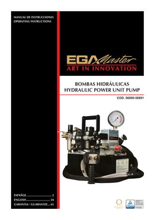
  • 1. BOMBAS HIDRÁULICAS HYDRAULIC POWER UNIT PUMP MANUAL DE INSTRUCCIONES OPERATING INSTRUCTIONS ESPAÑOL................................ 2 ENGLISH............................... 34 GARANTIA / GUARANTEE.... 65 COD. 56890-56891
  • 2. 2 NOTA Motor de aire de alta Resistencia. El motor de aire industrial de 4HP de potencia funciona a 60cfm/100PSI Indicador de presión extraíble. Opción de 4 puertos opcional. Conectores de conexión rápidas antigoteo. Suministrado con manguera doble de alta presión con conectores. La bomba se suministra sin aceite. El fabricante no se hace responsable de las modificaciones de las herramientas para aplicaciones en las cuales El fabricante no ha sido consultado. ADVERTENCIA INFORMACIÓN DE SEGURIDAD IMPORTANTE. LEER ESTE MANUAL ANTES DE TRABAJAR CON LA BOMBA. ES RESPONSABILIDAD DE LA EMPRESA EL FACILITAR ESTE MANUAL AL OPERARIO. EL CASO OMISO DE LAS SIGUIENTES ADVERTENCIAS PUEDEN PROVOCAR LESIONES. El fabricante ha preparado cuidadosamente este manual de funcionamiento que únicamente pretende ser una guía técnica. El fabricante no asume ninguna responsabilidad en relación con el uso de cualquier información contenida en este manual Toda la información, imágenes y especificaciones de este manual de funcionamiento están basados en la última información disponible en el momento de publicarlo. Se reserva el derecho de realizar cambios en cualquier momento sin previo aviso. Los trabajadores e instaladores del equipo serán los responsables de asegurar un ambiente de trabajo seguro y así como los sistemas de seguridad de trabajo que están en el lugar de trabajar con el equipo. EL CASO OMISO DE LAS SIGUIENTES ADVERTENCIAS PUEDEN PROVOCAR LESIONES. ESPAÑOL
  • 3. 3 NO exceder la máxima presión. Consultar la tabla de par de apriete de la herramienta ya que pueden producirse daños. ADVERTENCIA No use mangueras y accesorios dañados, desgastados o deteriorados. Utilice siempre gafas de seguridad al utilizar o realizar trabajos de mantenimiento en esta herramienta. Utilice siempre protección para los oídos al utilizar esta herramienta. No coja la herramienta por la manguera. Mantenga su cuerpo firme y en equilibrio. No se estire al utilizar esta herramienta. El brazo de reacción de la herramienta debe ser posicionado contra un punto de reacción adecuado. Tome todas las precauciones necesarias para asegurarse de que la mano del trabajador no pueda quedar atrapada entre el brazo de reacción y el punto de reacción. .
  • 4. 4 USO DE LA HERRAMIENTA • Mantenga las manos, la ropa holgada y el pelo largo alejados del brazo de reacción y de la zona de trabajo durante su funcionamiento • Esta herramienta ejercerá una gran fuerza de reacción. Utilice un soporte mecánico adecuado y controle la posición del brazo de reacción para controlar la fuerza. No coloque el brazo de reacción de una manera en la que la herramienta pueda posicionarse fuera del eje. No use nunca las entradas giratorias como brazo de reacción. • Evite curvas cerradas y retorceduras que puedan causar presión de aire en las mangueras y conllevara a fallos en las mangueras. • Utilice accesorios recomendados por el fabricante. • Utilice solo vasos y accesorios de impacto. • Utilice solo vasos y accesorios que se ajusten correctamente al tornillo o a la tuerca y que funcionen sin la necesidad de tener que sacar la herramienta fuera de la tuerca o tornillo. • Esta herramienta no está aislada contra descargas eléctricas. • Este equipo no debe usarse o repararse sin que el operario lea las instrucciones y entienda completamente el propósito, las consecuencias y el procedimiento paso a paso. Dependiendo del ambiente de trabajo y las normas de seguridad y salud locales, pueden requerirle un equipo de protección (protección para los oídos, zapatos de seguridad, casco de seguridad, guantes, monos, etc.). En caso de que las fuerzas externas ejerzan alguna fuerza sobre el equipo, el incumplimiento de estas normas puede provocar lesiones. DEBE UTILIZARSE PROTECCIÓN PARA LOS OIDOS AL USAR ESTA HERRAMIENTA. SEGURIDAD Y USO CORRECTO Operación del equipo de acuerdo a las especificaciones de uso 1. Inspeccione, mantenga, trabaje e instale la herramienta de acuerdo con las regulaciones y estándards aplicables (locales, nacionales, etc.) 2. No quite las etiquetas. Reemplace las etiquetas dañadas inmediatamente. 3. Asegúrese de que todas las mangueras y accesorios sean del tamaño correcto y están correctamente roscadas. 4. No utilice mangueras y accesorios desgastados o deteriorados. No pinte las mangueras. 5. No lubrique las herramientas con líquidos inflamables o volátiles tales como queroseno, gasoil o combustible para aviones. Use sólo lubricantes que recomienda El fabricante. 6. Use solamente los disolventes apropiados para limpiar las piezas. Utilice sólo disolventes de limpieza que cumplan las normas de seguridad y salud actuales. Utilícelos en un área bien ventilada. 7. Mantenga el área de trabajo limpia, despejada, ventilada e iluminada. Información de seguridad cuando se usa la herramienta 1. Cuando use guantes asegúrese siempre de que los guantes no impedirán que el mecanismo del acelerador sea liberado. 2. Siempre use protección para los ojos al operar o realizar el mantenimiento de esta herramienta.
  • 5. 5 3. Siempre use protección para los oídos cuando utilice esta herramienta. 4. Utilice siempre el equipo de protección personal adecuado a la herramienta utilizada y el material de trabajo. Esto puede incluir la máscara de polvo u otro aparato de respiración, gafas de seguridad, tapones para los oídos, guantes, delantal, zapatos de seguridad, casco y otros equipos. 5. Mantenga a otras personas a una distancia segura del área de trabajo, o asegúrese de que utilicen equipo de protección personal adecuado. 6. Tenga en cuenta los peligros ocultos o de otro tipo en su entorno de trabajo. No entre en contacto con cables, conductos, tuberías o mangueras que puedan contener hilos eléctricos, gases explosivos o líquidos nocivos. 7. Mantenga las manos, la ropa suelta, el cabello largo y las alhajas apartados del extremo de la herramienta de trabajo. 8. Las herramientas pueden vibrar durante su uso. Vibraciones, movimientos repetitivos o posiciones incómodas pueden ser perjudiciales para las manos y los brazos. Deje de usar cualquier herramienta si sobreviene una incomodidad, sensación de hormigueo o dolor. Consultar a un médico antes de reanudar. 9. Mantenga el cuerpo equilibrado y firme. No se estire demasiado cuando utilice esta herramienta. Anticipe y esté atento a los cambios repentinos en el movimiento, pares de reacción u otras fuerzas durante la puesta en marcha y operación. 10. No utilice esta herramienta cuando esté cansado, bajo la influencia de medicamentos, drogas o alcohol. 11. No utilice nunca una herramienta o un accesorio dañado o que no funciona correctamente. 12. No modifique las herramientas, los dispositivos de seguridad o accesorios. 13. No utilice esta herramienta para fines distintos a los recomendados 14. Nunca exceda la presión nominal de la herramienta. SEGURIDAD Y USO CORRECTO IMPORTANTE – LEER CUIDADOSAMENTE Este manual contiene información importante para la instalación, funcionamiento y mantenimiento correcto de este equipo. Todas las personas involucradas en la instalación, funcionamiento y mantenimiento de este equipo deben estar totalmente familiarizadas con el contenido de este manual. Para evitar posibles daños personales o materiales, siga las recomendaciones e instrucciones de este manual. Mantenga este manual como referencia. DECLARACIÓN DE GARANTÍA Los productos de El fabricante están garantizados para estar libres de defectos en materiales y bajo un uso normal durante el tiempo que el comprador original sea su propietario, con sujeción a las directrices y limitaciones enumeradas. Esta garantía no cubre: desgaste normal, abusos, sobrecargas, alteraciones, fluido incorrecto, o el uso en una manera para la cual no están destinados. Si el cliente cree que un producto es defectuoso, el producto debe ser entregado a El fabricante. La bomba dispone de una garantía de 12 meses. .
  • 6. 6 INSTRUCTIONES AL RECIBIR EL ENVÍO ¡Importante! Asegúrese de inspeccionar todos los componentes debido a daños en el transporte. Si encuentra cualquier daño, notifíquelo inmediatamente al transportista. Lo daños debidos al transporte no son cubiertos por la garantía. El transportista es responsable todas las pérdidas asociadas a los daños en el transporte. SEGURIDAD Asegúrese de leer cuidadosamente todas las instrucciones, advertencias y precauciones. Siga las precauciones de seguridad recomendadas para evitar daños personales o materiales en el equipo. El fabricante no se hace responsable de ningún daño o lesión debido a un uso inseguro, falta de mantenimiento o uso incorrecto. En caso de duda, consulte con El fabricante. La máxima presión de trabajo de la bomba es 10.000 PSI (700kg/cm2). Asegúrese de que todos los equipos hidráulicos como mangueras, etc. empleados con esta bomba puedan usarse a la presión de trabajo de 10.000 PSI (700kg/cm2). El incumplimiento de las siguientes precauciones y advertencias puede causar daños al equipo, daños materiales o lesiones personales. PELIGRO es únicamente usado cuando su acción o falta de acción puede causar lesiones graves o incluso la muerte. ADVERTENCIA indica un peligro potencial que requiere procedimientos o prácticas correctas para evitar daños personales. PRECAUCIÓN es usado para indicar procedimientos de trabajo o mantenimiento correctos así como prácticas para prevenir daños, o destrucción del equipo, u otros daños materiales. SEGURIDAD Y USO CORRECTO ADVERTENCIA: Use un equipo de protección personal adecuado cuando trabaje con el equipo hidráulico. PELIGRO: Para evitar daños personales, mantenga las manos y pies lejos de la zona de trabajo durante la operación. ADVERTENCIA: No exceda los límites del equipo. La sobrecarga puede causar el fallo del equipo e incluso daños personales. La bomba está diseñada para una presión máxima de 10.000 PSI (700kg/cm2). No conecte un gato o cilindro a la bomba. Nunca fije la válvula de alivio a una presión superior a la presión nominal máxima de la bomba. Los ajustes más altos pueden causar daños en el equipo y / o lesiones personales. ADVERTENCIA: El presión de trabajo del sistema no debe exceder la presión nominal de la pieza de menor potencia del sistema. Instalar medidores de presión en el sistema para monitorizar la presión de trabajo.
  • 7. 7 PRECAUCIÓN: evite dañar las mangueras hidráulicas. Evite pliegues y curvas agudos al guiar las mangueras hidráulicas para evitar daños internos la manguera, lo que lleva a la falla prematura de la manguera. No deje caer objetos pesados sobre la manguera. Un impacto directo puede causar daños internos a las hebras de alambre de la manguera. La aplicación de presión a una manguera dañada puede hacer que se rompa. IMPORTANTE: No coja el equipo hidráulico por las mangueras o conectores giratorios. Utilice el asa de transporte u otros medios un transporte seguro. PRECAUCIÓN: Mantenga el equipo hidráulico lejos de las llamas o calor. Un calor excesivo puede ablandar las juntas provocando fugas de líquidos. El calor también debilita los materiales de la manguera. Para un rendimiento óptimo no exponga al equipo a temperaturas de 65° C (170° F) o mayores. Proteja las mangueras o cilindros de posibles salpicaduras de soldadura. ESPECIFICACIONES TÉCNICAS Capacidad útil del depósito A B C D E (Gal.) (litre) (in) (mm) (in) (mm) (in) (mm) (in) (mm) (in) (mm) 1.5 5.7 15.13 384.3 19.09 484.88 15.89 406.48 5.94 150.88 8.75 222.25 Weight is without oil Modelo Capacidad del depósito Válvula Mando de control Especificaciones del motor Flujo Peso Gal. Litre Modelo Tipo Función lbs. Kg 56890 1.5 5,7 Torque Auto Retract Advance/ Retract Motor/ Solenoid Control 4HP @ 100psi/ 60cfm 700 cu. in./ min. @1,100 psi 55 cu.in./ min.@10,000 psi 63.75 28.92
  • 8. 8 PRESIÓN DE TRABAJO La presión de trabajo máxima de la bomba es 10.000 PSI (700kg/cm2). Asegurese de que todos los equipos hidráulicos como herramientas, mangueras, etc., usados con esta bomba pueden trabajar con una presión de 10,000 PSI (700kg/cm2). ESPECIFICACIONES TÉCNICAS INSTALACIÓN DEL TAPÓN DE DESAIREACIÓN Retire el TAPÓN DE ENVÍO (A) e instale el TAPÓN DE DESAIREACIÓN (B) en la cubierta. LLENADO DEL DEPÓSITO Retire el TAPÓN DE ACEITE (C) y añada aceite hidráulico en el depósito. El nivel de aceite no debe exceder de 1” sobre desde la parte superior del depósito.
  • 9. 9 * Como regla el depósito de aceite se debe llenar un pulgada por debajo de la parte superior del depósito cuando la bomba está apagada y todas las herramientas o cilindros conectados retraídos. ADVERTENCIA Las conexiones sueltas o mal roscadas pueden ser potencialmente peligrosas si están bajo presión. Sin embargo, un apriete excesivo puede dañar la rosca. Los accesorios necesitan ser unidos de forma segura y libre de fugas. Nunca sujete o pare directamente sobre las conexiones hidráulicas cuando están bajo presión. Nunca agarre, toque o esté en contacto con una fuga de presión hidráulica. Un escape de aceite puede penetrar en la piel y provocar serios daños. CONEXIÓN DE LAS HERRAMIENTAS HIDRÁULICAS Use únicamente herramientas, mangueras o accesorios clasificados con una presión de 10,000 PSI (700kg/cm2). Cuando realice las conexiones con los conectores rápidos de conexión, asegúrese de que los conectores están completamente unidos. Las conexiones roscadas tales como accesorios, indicadores, etc., deben estar bien apretados y sin fugas. Utilice de cinta de teflón (o sellador de roscas adecuado) en todas las roscas, dejando el primer hilo de la rosca libre para asegurar que ningún cuerpo extraño entra en el circuito hidráulico. PRECAUCIÓN: No someta la manguera a peligros potenciales, tales como superficies afiladas, calor extremo o impactos fuertes. No permita que la manguera se doble o se tuerza. Inspeccionar el desgaste de cada manguera antes de utilizarla. MONTAJE DE LA BOMBA Consulte la table de las dimensiones de montaje para asegurar la bomba en una superficie fija.. 1.5 gal (6L) 2.5 gal. (10L) A 15.13 17 B 3.68 4.75 C 1.57 2.37 D 1.43 1.93 E 8.75 9.75 F 1/4-20OUNC (4 PLACAS) 1/4-20OUNC (4 PLACAS)
  • 10. 10 ESPECIFICACIONES TÉCNICAS BOTONES DE CONTROL DE AIRE RUN = Mantenga pulsado el botón para activar el solenoid y se encienda la bomba STOP = Suelte el botón RUN y presione este botón para parar el motor. PULSAR PARA AVANZAR PULSAR PARA PARAR ADVERTENCIA Realice estos ajustes antes de colocar la llave de apriete en la tuerca o cabeza del tornillo. El ajuste de presión de la bomba puede estar por encima de la presión necesaria para proporcionar el par necesario para su aplicación. Exceder el par de apriete requerido puede causar daños en el equipo y puede dar lugar a lesiones personales graves.
  • 11. 11 AJUSTE DE LA PRESIÓN DEL PAR DE APRIETE 1. Consulte las instrucciones de la llave de apriete para conocer la presión requerida para producir el par de apriete requerido. 2. Afloje la tuerca de bloqueo y saque la válvula de alivio para prevenir acumulaciones de presión involuntarias 3. Encienda la bomba. Presione el botón RUN y lea la presión en el indicador. 4. Mientras mantiene pulsado el botón, gire la válvula de alivio (a la derecha) para aumentar la presión o hacia fuera (hacia la izquierda) para disminuir la presión máxima. Repita la operación hasta obtener la presión correcta. 5. Apriete la tuerca de bloqueo de la válvula de seguridad para mantener la presión ajustada 6. Haga funcionar la bomba varias veces para probar esta configuración antes de colocar la herramienta en la tuerca. BOTÓN DE AJUSTE TUERCA DE BLOQUEO VÁLVULA DE ALIVIO ESPECIFICACIONES TÉCNICAS MOTOR DE AIRE Y FILTRO LUBRICADOR El motor de aire es un motor rotativo construido a precisión. La holgura superior (entre el rotor y el agujero) es de 0,0015 “. El espacio final total (entre los lados del rotor y las placas extremas es 0,002 “). Los álabes tienen su propio desgaste y tendrán una duración de 5.000- 12.000 horas, dependiendo de la velocidad, el método de lubricación, presión de trabajo, y si trabaja a una presión de trabajo por encima de 100 PSI (6.89 Bar-métrico). El exceso de humedad o partículas extrañas de la línea de aire en el motor anulará la garantía. Se ha instalado un filtro para la humedad en la línea de aire por la parte delantera del motor. Para una mayor eficiencia y control de la velocidad, utilizar una manguera de aire de no menos de 1/2 “de diámetro. Al acoplar o conectar el motor a una unidad, evite que cualquier extremo empuje el lateral del eje de salida y sobre todo NO golpee el EJE.
  • 12. 12 El par de arranque es mayor que el par de funcionamiento y podría variar dependiendo de la posición en la que los álabes se detienen en relación con el orificio de admisión de aire. La velocidad y el par se puede regular mediante el uso de un regulador de presión o una simple válvula de cierre. La lubricación es necesaria para la junta del eje, y la prevención de la oxidación. Cada bomba accionada por aire está equipada con un conjunto automático de aceite para la manguera de aire que la alimenta a 1-3 gotas por minuto. Una humedad excesiva en la línea puede causar la formación de óxido en el motor y también podría causar que se forme hielo en silenciador debido a la expansión de aire a través del motor. Si el motor funciona lento o es ineficiente, intente descárgalo con un disolvente en un área bien ventilada. Desconecte la línea de aire, conecte la línea de aire nuevamente y aplique presión lentamente hasta que no haya rastro de disolvente en el aire de escape (mantenga la cara alejada). Compruebe los filtros del silenciador de grasa, suciedad, etc. Si está sucio, lávelos con disolvente. Reemplace los filtros y conecte el silenciador. Lubrique el motor con un chorrito de aceite en la cámara. Si hay que sustituir los álabes o hay partículas extrañas en la cámara del motor, un mecánico experimentado puede quitar la placa final para llevarlo a cabo. ADVERTENCIA Para evitar el riesgo de explosión, no bombee líquidos o vapores combustibles a través de estas unidades. RECOMENDACIONES UNA VEZ FINALIZADO EL TRABAJO Antes de desconectar las mangueras, conexiones, etc. primero asegúrese de que la herramienta está descargada y retraída, a continuación, desconecte la línea de aire y cambie los controles hidráulicos varias veces para liberar la presión del sistema. Guarde la bomba en un lugar limpio y seco. MANTENIMIENTO DEL NIVEL DE ACEITE Compruebe el nivel de aceite hidráulico cada 30 horas de funcionamiento (el indicador debe estar completamente cubierto de aceite cuando se retiran todas las herramientas. Añadir aceite cuando sea necesario. El nivel de aceite no debe ser mayor de 1 “de la parte superior del depósito - con los cilindros retraídos y el motor apagado. PROCEDIMIENTOS DE OPERACIÓN MANTENIMIENTO PERIÓDICO Cambie completamente el aceite hidráulico y limpie la rejilla de la entrada y el imán (que se encuentra en el depósito) dos veces al año. Si tiene filtro de aceite externo, cámbielo dos veces al año (utilice el aceite adecuado). Cambie el aceite con mayor frecuencia cuando se utiliza en áreas con mucho polvo o cuando el aceite se haya sobrecalentado. El uso de un aceite inadecuado puede anular la garantía de la bomba. Las siguientes condiciones requieren cambios de aceite más frecuentes.
  • 13. 13 • Aplicaciones rigurosas donde la temperatura del aceite puede llegar a 150˚ F. • Entornos de alta humedad o con cambios bruscos de temperatura que pueden provocar condensación en el interior del depósito. • Ambientes sucios o polvorientos que pueden contaminar el aceite. • Cuando se realizan conexiones y desconexiones frecuentes de las mangueras y los componentes hidráulicos. LIMPIEZA DE LA REJILLA DE ADMISIÓN DE ACEITE UNA VEZ AL AÑO Afloje y retire los tornillos de la placa del depósito. Levante la unidad de la bomba del depósito, teniendo cuidado de no dañar la junta. Para depósitos de 1.5, 2, 2.5 galones: Retire los cinco tornillos de cabeza allen, asegurando la pantalla a la primera fase en los engranajes de la bomba. Se debe tener cuidado de no retirar la placa central y los engranajes. Retire y limpie con disolvente no inflamable y un trapo seco y limpio. Vuelva a colocar en orden los tornillos y apriételos a un par de 75 lb.in. Mantenga el motor y la bomba lo más limpia posible. Para depósitos de 5 y 10 galones: Desenrosque la pantalla de la parte inferior de la bomba y límpielo con disolvente no inflamable. Vuelva a montarlo manteniendo las áreas de alrededor de la bomba sin obstrucciones para proporcionar un buen flujo de aire alrededor del motor y la bomba. Mantenga el motor y la bomba lo más limpia posible. LIMPIEZA DE LA BOMBA Si sospecha que su bomba ha sido contaminada o descubre lodo u otros depósitos en los componentes internos, debe enjuagar completamente la bomba. Quite el aceite del depósito, limpie a fondo el depósito y rellénelo con un aceite de aclarado inflamable limpio. Monte la bomba y el motor al depósito. Haga funcionar la bomba en condiciones de carga durante 1 o 2 minutos como máximo. Desenchufe la bomba y retire el motor y la bomba de nuevo. Ahora drene el aceite de enjuague y vuelva a limpiar el interior del depósito. (Asegúrese de que el fluido limpio es también drenado desde el conjunto de la bomba). Monte la bomba y vuelva a llenar el depósito con el aceite hidráulico adecuado. LLENADO DE ACEITE (1.5 – 10 GAL) INDICADOR DE ACEITE TAPÓN DE DRENAJE (1.5 – 10 GAL)
  • 14. 14 LIMPIEZA DE LA BOMBA PROBLEMA CAUSA - SOLUCIÓN Accionamiento esporádico de la herramienta • Aire en el sistema hidráulico. Purgar el circuito hidráulico. • Chequear el nivel de aceite del depósito. El motor no arranca • Demasiada agua en la línea de aire. Motor congelado. • Presión de aire insuficiente. • Chequear el correcto funcionamiento del motor. • Chequear el botón de ajuste del aire FRL. Funcionamiento ruidoso • Aire en el sistema. • Asegúrese de que el depósito de aceite está lleno hasta el nivel adecuado. • Compruebe todos los puntos en los que el aire podría filtrarse en el sistema • Rejilla de entrada obstruida o bloqueada El aceite de la bomba está sobrecalentada • Inspeccione si hay fugas de alta presión en la bomba (fugas en el tapón o válvula de alivio). • El nivel de aceite es bajo. Rellene el depósito hasta su nivel normal, o instale un intercambiador de calor en la bomba. La bomba funciona pero no alcanza la presión • La bomba no está preparada. Arranque la bomba unos minutos inclinándola de lado a lado. • Compruebe que la válvula de alivio ajustable externa está configurada correctamente. • Válvula de control defectuosa, llévela al fabricante para reparar. • Asegúrese de que la rejilla de entrada no esté obstruida. Límpiela si es necesario. • Compruebe si el nivel de aceite es bajo. Rellene según sea necesario. • La viscosidad del aceite es demasiado alta. Reemplace por el aceite adecuado. • Línea de suministro de aire demasiado pequeña. • No hay suficiente presión de aire. ÍNDICE DE REPUESTOS Esta imagen es solo para fines de referencia. La apariencia de la unidad puede diferir de la unidad mostrada.
  • 15. 15 SUBCONJUNTO Y SUB COMPONENTES DE LA BOMBA MANDO DE CONTROL REMOTO COMPONENTES COMUNES DEPÓSITO SUBCONJUNTOS DE LA VÁLVULA SUBCONJUNTO DEL COLECTOR ÍNDICE DE REPUESTOS Cómo identificar los repuestos de su modelo. Nº DE MODELO & LOCALIZACIÓN DEL CÓDIGO DE FECHA Por ejemplo, el código de fecha y el nº de serie J = Octubre 07 = Año 2007 42 = Nº de la semana en el año J 07 42 A B C D E F G H I J K L 1 2 3 4 5 6 7 8 9 10 11 12 UBICACIÓN DEL CÓDIGO DE LA FECHA QUE SE ESTAMPA EN LA PLACA SUPERIOR
  • 16. 16 COMPONENTES COMUNES Nota: Esta ilustración es únicamente como referencia. La apariencia de su unidad puede diferir de la unidad mostrada. VÁLVULA DE CONTROL DE AIRE VÁLVULA DE DOBLE EFECTO VÁLVULA DE DOBLE EFECTO FILTRO / LUBRICADOR NOTAS: BOMBA PROBADA PARA UN FLUJO DE @ 0, 5,000, 10,000 PSI. FLUJO DE REGISTRO, RPM, Y PRESIÓN DE AIRE. SET DE MEZCLA @ 1,200-1,300 PSI. SET INTERIOR DE ALIVIO @ 10,200-10,500 PSI. SET DE ALIVIO DE RETRACCIÓN @ 1,700-1,800 PSI. MANDO DE CONTROL REMOTO Y MANGUERA MANDO DE CONTROL REMOTO NEGRO NEGRO AMARILLO AMARILLO
  • 17. 17 TAPÓN DE ENVÍO Y TAPÓN DE VENTILACIÓN NOTAS DE MONTAJE: PAR DE APRIETE DE 225-275 IN*LBS PAR DE APRIETE DE 45-55 IN*LBS PAR DE APRIETE DE 18-22 IN*LBS PAR DE APRIETE DE 68-82 IN*LBS APLICAR TEFLÓN & PAR DE APRIETE DE 32-39 FT*LBS APLICAR TEFLÓN & PAR DE APRIETE DE 80-100 IN*LBS APLICAR TEFLÓN & PAR DE APRIETE DE 20-25 FT*LBS AÑADIR 5-10 GOTAS DE ACEITE EN EL MONTAJE ANTES DE INSTALAR EN EL MOTOR APLICAR LOCTITE & PAR DE APRIETE DE 60-72 IN*LBS
  • 18. 18
  • 19. 19 ITEM DESCRIPCIÓN CANTIDAD 0 ACEITE HIDRÁULICO 1 QT. 2 0 ACEITE HIDRÁULICO-1 GAL. 1 2 BOMBA DE DOS ETAPAS 1 3 DEPÓSITO NEGRO DE 1.5 GAL 1 4 JUNTAS DEL DEPÓSITO 1 5 RESPIRADERO 3/8 NPT 1 6 SELLADOR 1 7 CONECTOR HEX CON PUERTO 1 8 1/4-20 X .75 HHCS ZINC 14 9 ARANDELA DE SELLADO 14 13 COLECTOR 1 14 VÁLVULA DE JUNTAS 1 15 SHCS 3/8-16 X 2 3/4 3 16 CONJUNTO ADAPTADOR 1 17 CONECTOR 1 19 SOLENOIDE DE AIRE 4W/2P NORMALMENTE RETRAIDO 1 20 SHCS 3/8-16 X 3 1/2 4 21 ARANDELA DE SEGURIDAD 6 22 MUELLE PASADOR 1 24 IMÁN 1 41 MANDO DE CONTROL REMOTO 1 45 ASA 1 52 INDICADOR 1 57 BOQUILLA 1/4” 1 58 BOQUILLA 1/4” 1 59 1/4" ACOPLADOR AUTOBLOQUEANTE 2 62 HHCS .25-28x 1.25 ZINC 2 63 ARANDELA PLANA M6 2 70 JUNTA-MOTOR 2 71 JUNTA-BOMBA G5 1 72 CODO 1 73 CUBIERTA G5 1 74 PIN DOBLE DE LONGITUD 3/16" x 2" 1 75 SHCS 3/8-16 X 3/4 LG 4 76 MOTOR DE AIRE PINTADO DE NEGRO 1 78 FHCS DE LONGITUD 1/4-28 x 0.50 4 79 PUNTO MUERTO DEL MOTOR 1 81 CODO MACHO 1/2 NPT 2 82 CONJUNTO DE VÁLVULA PARA CONTROL DE AIRE 1 83 BOQUILLA HEX MACHO 1/4 - 1/8 1 84 VÁLVULA DE DOBLE EFECTO 1 86 FILTRO / LUBRICADOR 1 87 MANGUERA DE TUBO MACHO 1 88 ABRAZADERA DE LA MANGUERA 2 89 MANGUERA 1 90 FILTRO REGULADOR / LUBRICADOR 3/8" NPT 1 91 MANGUERA 12 92 TUBO DE NYLON 30 94 SILENCIADOR ZA4 1 95 TUBO CODO MACHO 1/4 2 96 SHCS 1/4-20 X 1/2 2 97 TUERCA HEX (.250-20) 2 98 VÁLVULA DE FLUJO CONT 3/8" NPT 1
  • 20. 20 CONJUNTO DE LA BOMBA PAR DE APRIETE DE 350 IN*LBS. PAR DE APRIETE DE 350 IN*LBS. PAR DE APRIETE DE 130 IN*LBS. PAR DE APRIETE DE 130 IN*LBS. PAR DE APRIETE DE 130 IN*LBS. PAR DE APRIETE DE 350 IN*LBS.
  • 21. 21 PAR DE APRIETE DE 90 IN*LBS. PAR DE APRIETE DE 90 IN*LBS. PAR DE APRIETE DE 120 IN*LBS. PAR DE APRIETE DE 175 IN*LBS. PAR DE APRIETE DE 175 IN*LBS. PAR DE APRIETE DE 120 IN*LBS. PAR DE APRIETE DE 25 IN*LBS. PAR DE APRIETE DE 90 IN*LBS.
  • 22. 22 PAR DE APRIETE DE 90 IN*LBS PAR DE APRIETE DE 175 IN*LBS PAR DE APRIETE DE 175 IN*LBS PAR DE APRIETE DE 90 IN*LBS PAR DE APRIETE DE 75 IN*LBS PAR DE APRIETE DE 75 IN*LBS PAR DE APRIETE DE 75 IN*LBS PAR DE APRIETE DE 90 IN*LBS PAR DE APRIETE DE 90 IN*LBS PAR DE APRIETE DE 130 IN*LBS
  • 23. 23 ITEM DESCRIPCIÓN CANTIDAD 1 CUERPO DE LA BOMBA 1 2 RODAMIENTO 5/8x13/16x5/8 ANCHO 1 3 COJINETE DE EMPUJE 1 4 ARANDELA DE EMPUJE 2 5 EJE EXCÉNTRICO ASM 5/8" 1 6 COJINETE DE EMPUJE 1 7 ARANDELA DE EMPUJE 2 8 ADAPTADOR DEL EJE EXCÉNTRICO 1 9 JUNTA TÓRICA 1 3/4 X 1 7/8 1 10 JUNTA DE RETENCIÓN 1 11 ENCHUFE 1 12 JUNTA TÓRICA 3/16X5/16 3 13 ARANDELA 1 14 SOPORTE MACHO TUBO 1/8" A TUBO 1/4" 1 15 CONECTOR DE TUBO 1/4" 1 16 CONJUNTO DE PISTÓN DE DESCARGA 2 17 SOPORTE MACHO TUBO 1/4" A TUBO 1/4" 1 18 BOLA 1/8" 2 19 TUBO DE BLOQUEO DEL PISTÓN 1 20 TUBO DE SALIDA DEL BLOQUEO DEL PISTÓN 1 21 BOLA 5/16" 3 22 MUELLE DE DESCARGA 1 23 TORNILLO DE AJUSTE 1 24 JUNTA TÓRICA 5/8X3/4 1 25 CONECTOR DE TUBO 1/16 7 27 CARCASA SUPERIOR 1 28 JUEGO DE ENGRANAJES 9/33” 1 29 EJE 1 30 REJILLA 1 31 TUBO. GUÍA .11 2 32 SHCS 1/4-28 X 1 3/4 5 33 PLACA DE LA REJILLA 1 34 SOPORTE DE TUBO 1/8 1 35 MUELLE 2 36 PASADOR LONGITUD 1/8 X 3/4 1 37 BOLA DE PARADA 2 38 JUNTA 29/64 X 5/8 2 39 VÁLVULA DE DESCARGA 1 41 TUBO DE RETORNO 1 43 RODAMIENTO ANCHO1 1/4x1 1/2x3/4 1 44 RODAMIENTO 1/2x11/16x1/2 3 45 ANILLA DE RETENCIÓN 1 46 CONECTOR DE TUBO 1/8” 1 47 CONJUNTO DE LA VÁLVULA 1 48 SELLO DEL EJE 1 49 BLOQUEO DEL PISTÓN 0.255" 2 50 SHCS 5/16-24 X 1.75 8
  • 24. 24 CONJUNTO DEL PISTÓN DE DESCARGA ITEM DESCRIPCIÓN CANTIDAD 01 DESCARGA DE PISTÓN 1 02 JUNTA TÓRICA 1/4X3/8 1 03 ARANDELA DE RESPALDO 1 04 PIN DOBLE 1/8X3/4 1 PAR DE APRIETE DE 400 IN*LBS PAR DE APRIETE DE 25 IN*LBS PAR DE APRIETE DE 150 IN*LBS PAR DE APRIETE DE 200 IN*LBS ITEM DESCRIPCIÓN CANTIDAD 1 BLOQUEO DEL PISTÓN 1 2 BOLA 1/8" 2 3 MUELLE 1 4 BOLA DE PARADA 1 5 BOLA RETENEDORA 1 6 ASIENTO DE ENTRADA 1 7 JUNTA 25/64X19/32 1 8 BLOQUE TAPÓN DEL PISTÓN 1 9 JUNTA 29/64 X 5/8 1 10 ADAPTADOR .255 DIA. 1 11 MUELLE, PISTÓN 1 12 PISTÓN .255 DIA. 1
  • 25. 25 CONJUNTO DE LA VÁLVULA ESQUEMA HIDRÁULICO PAR DE APRIETE DE 50 IN*LBS PAR DE APRIETE DE 50 IN*LBS PAR DE APRIETE DE 150 IN*LBS PAR DE APRIETE DE 25 IN*LBS PAR DE APRIETE DE 75 IN*LBS 4 POSICIONES PAR DE APRIETE DE 84-108 IN*LBS
  • 26. 26 ITEM DESCRIPCIÓN CANTIDAD 1 CUERPO DE LA VÁLVULA 1 2 RESBALADOR 1 3 BOLA 3/16" 4 4 JUEGO DE TORNILLOS 1/4-28 X 1/4 4 5 CONJUNTO DEL CILINDRO DE AIRE 1 6 JUNTA TÓRICA 7/32X11/32 3 7 ARANDELA 3 8 JUNTA 3 9 MUELLE 3 10 JUNTA TÓRICA 2 5/8 X 2 3/4 1 11 RODAMIENTO 5/16x1/2x5/16 4 12 PIN DEL RODAMIENTO 2 13 JUEGO DE TORNILLOS 5/16-18 X 1/4 1 14 SHCS #10-32 X 1" LG 2 15 PLACA DE LA VÁLVULA 1 16 SHCS #10-24 X 3.25" 4 17 JUNTA TÓRICA 3/16X5/16 1 18 BOLA 1/4" 1 19 DESLIZAMIENTO DEL TAPÓN DE LA VÁLVULA DE DOS POSICIONES 1 26 JUNTA TÓRICA 1 27 MUELLE 1 29 ESPACIADOR DEL DESLIZAMIENTO DE LA VÁLVULA 1 31 JUNTA TÓRICA 5/16X7/16 4 ADAPTADOR DE LA VÁLVULA ITEM DESCRIPCIÓN CANTIDAD 1 ADAPTADOR DE LA VÁLVULA 1 2 ANILLA 2 3 JUNTA TÓRICA 3/8X1/2 2
  • 27. 27 ITEM DESCRIPCIÓN CANTIDAD 1 CUERPO DEL CILINDRO 1 2 JUNTA TÓRICA 1/8 X 1/4 1 3 JUNTA TÓRICA 1/4X3/8 1 4 PISTÓN 1 5 MUELLE 1 7 CUBIERTA FINAL 1 8 JUNTA TÓRICA 1 1/16X1 3/16 1 9 JUNTA 1 10 JUNTA TÓRICA 11/16X13/16 1 11 JUNTA TÓRICA 1 12 VÁLVULA 1 13 PIN DE ANULACIÓN 1 14 ANILLA EJE JUNTO 1/4" 1 15 PLACA DE LA CÁMARA DE AIRE DE LA VÁLVULA 1
  • 28. 28 CONJUNTO DE LA VÁLVULA DE CONTROL DE AIRE ITEM DESCRIPCIÓN CANTIDAD 100 VÁLVULA DE CONTROL DE AIRE 1/2 PUERTOS 1 101 CODO GIRATORIO 1/2 NPT 1 102 ADAPTADOR GIRATORIO 1/8 1 103 ADAPTADOR DE TUBO 1/2-1/8 1 104 ADAPTADOR EN T 1/2" NPT 1 105 CODO DE MANGUERA DE 1/2 NPT A 1/2 1 106 1/8 T GIRATORIA 2 107 CODO GIRATORIO 2 108 SELLADOR 1/2 1
  • 29. 29 CONJUNTO DEL COLECTOR PAR DE APRIETE DE 120 IN*LBS PAR DE APRIETE DE 225 IN*LBS PAR DE APRIETE DE 120 IN*LBS PAR DE APRIETE DE 50 IN*LBS PAR DE APRIETE DE 120 IN*LBS PAR DE APRIETE DE 120 IN*LBS PAR DE APRIETE DE 50 IN*LBS PAR DE APRIETE DE 120 IN*LBS PAR DE APRIETE DE 50 IN*LBS
  • 30. 30 ITEM DESCRIPCIÓN CANTIDAD 01 VÁLVULA DEL COLECTOR 1 02 SOPORTE DE LA VÁLVULA DE ALIVIO 1 03 CONECTOR PARA TUBO 1/16 3 04 CONECTOR PARA TUBO 1/8 3 05 BOQULLA DE TUBO 1/8 NPT 1 06 ACOPLADOR DE TUBO 1/8 1 07 CONJUNTO INTERIOR HF 1 ITEM DESCRIPCIÓN CANTIDAD 01 CARTUCHO 1 02 CONO DE LA VÁLVULA 1 03 MUELLE 1 04 TORNILLO DE AJUSTE 1 05 TUERCA HEXAGONAL 7/16-20 1
  • 31. 31 CONJUNTO DEL MANDO DE CONTROL REMOTO ITEM DESCRIPCIÓN CANTIDAD 1 CUERPO DEL MANDO 1 2 MÓDULO DE BLOQUEO 1 3 CARTUCHO-AIRE 2 4 ADAPTADOR GIRATORIO 1/8 3 5 BOLA 5/32 3 6 ANILLA DE RETENCIÓN 2 7 CAPUCHÓN DEL CARTUCHO 2
  • 32. 32 DEPÓSITO ITEM DESCRIPCIÓN CANTIDAD 03 DEPÓSITO 1 04 JUNTA DEL DEPÓSITO 1 05 RESPIRADERO 3/8" NPT 1 06 TAPÓN 1 07 TAPÓN HEXAGONAL CON PUERTO 1 08 HHCS 1/4-20 x 3/4 LG 14 09 ARANDELA SELLADORA 14 10 RESERVOIR DECAL 1 52 INDICADOR 1 73 CUBIERTA DEL DEPÓSITO 1
  • 33. 33
  • 34. 34 NOTICE Heavy duty air motor. Powerful 4HP industrial air motor runs on 60cfm/100PSI Disconnect removable pressure gauge. “Quadra”function (optional). Quick connect couplers. Supplied with dual non-conductive high pressure hose with couplers. The pump is supplied without oil. The manufacturer is not responsible for customer modification of tools for applications on which the manufacturer was not consulted. WARNING IMPORTANT SAFETY INFORMATION ENCLOSED. READ THIS MANUAL BEFORE OPERATING PUMP. IT IS THE RESPONSIBILITY OF THE EMPLOYER TO PLACE THE INFORMATION IN THIS MANUAL INTO THE HANDS OF THE OPERATOR. The manufacturer has taken every care in preparing this Operational Manual that is intended as a technical guideline only. The manufacturer accepts no liability in relation to any use or reliance made of any information in this Operational Manual. All information, illustrations and specifications in this Operational Manual are based on the latest information avail- able at the time of publication. The right is reserved to make changes at any time without notice. Equipment operators and installers shall be responsible for ensuring that a safe working environment and safe systems of work are in place before operating the equipment. Do NOT exceed Maximum Pressure. See Torque Chart with Tool. Damage May Occur. ENGLISH
  • 35. 35 WARNING Do not use damaged, frayed or deteriorated air/pneumatic hoses and fittings. Always wear eye protection when operating or performing maintenance on this tool. Always wear ear protection when operating this tool. Do not carry the tool by the hose. Keep body stance balanced and firm.Do not overreach when operating this tool The Torque Reaction Arm must be positioned against a positive stop. Do not use the arm as a dead handle. Take all precautions to make certain the operator’s hand cannot be pinched between the arm and a solid object.
  • 36. 36 USING THE TOOL • Keep hands, loose clothing & long hair away from the reaction arm and working area during operation. • This tool will exert a strong reaction force. Use proper mechanical support and correct reaction arm positioning to control these forces. Do not position the reaction arm so that it tilts the tool off the axis of the bolt and never use the swivel inlets as a reaction stop. • Avoid sharp bends and kinks that will cause severe back-up pressure in hoses an lead to premature hose failure. • Use accessories recommended by The manufacturer. • Use only impact sockets and accessories. Do not use hand (chrome) sockets or accessories. • Use only sockets and accessories that correctly fit the bolt or nut and function without tilting the tool off the axis of the bolt. • This tool is not insulated against electric shock. • This equipment must not be operated or serviced unless the operator read the operating instructions and fully understands the purpose, consequences and procedure of each step. Depending on the working environment your local health and safety regulations may require you protective gear (i.e. Ear Protection, Safety Shoes, Hard Hat, Gloves, Coveralls, etc.) In case external forces are exerted on the equipment, non-compliance with these regulations may result in injury. EAR PROTECTION MUST BE WORN WHEN OPERATING THIS TOOL. SAFE AND CORRECT USE Operation of the Equipment in Accordance with Specified Use 1. Inspect, maintain, operate and install the tool in accordance with all applicable standards and regulations (local, state, country, federal, etc.) 2. Do not remove any labels. Replace any damaged labels immediately. 3. Be sure all hoses and fittings are the correct size and tightly secured. 4. Do not use damage, frayed or deteriorated air hoses and fittings. Do not paint hoses. 5. Do not lubricate tools with flammable or volatile liquids such as kerosene, diesel or jet fuel. Use only The manufacturer recommended lubricants. 6. Use only proper cleaning solvents to clean parts. Use only cleaning solvents which meet cur-rently safety and health standards. Use cleaning solvents in a well ventilated area. 7. Keep work area clean, uncluttered, ventilated and illuminated. Safety Information When Using The Tool 1. When wearing gloves always be sure that the gloves will not prevent the throttle mechanism from being released. 2. Always wear eye protection when operating or performing maintenance on this tool. 3. Always wear hearing protection when operating this tool. 4. Always use personal protective equipment appropriate to the tool used and material worked. This may include dust mask or other breathing apparatus, safety glasses, ear plugs, gloves, apron, safety shoes, hard hat and other equipment. 5. Keep others a safe distance from your work area, or ensure they use appropriate personal protective equipment. 6. Be aware of buried, hidden or other hazards in your work environment. Do not contact or dam-age cords, conduits, pipes, or hoses that may contain electrical wires, explosive gases or harmful liquids.
  • 37. 37 7. Keep hands, loose clothing, long hair and jewelry away from working end of tool. 8. Power tools can vibrate in use. Vibration, repetitive motions or uncomfortable positions may be harmful to your hands and arms. Stop using any tool if discomfort, tingling feeling or pain occurs. Seek medical advice before resuming. 9. Keep body stand balanced and firm. Do not overreach when operating this tool. Anticipate and be alert for sudden changes in motion, reaction torques, or forces during start up and operation. 10. Do not use this tool when tired, under the influence of medication, drugs or alcohol. 11. Never use a damaged or malfunctioning tool or accessory. 12. Do not modify the tools, safety devices or accessories. 13. Do not use this tool for purposes other than those recommended 14. Never exceed rated pressure of tool. SAFE AND CORRECT USE IMPORTANT - READ CAREFULLY This manual contains important information for the correct installation, operation and maintenance of this equipment. All persons involved in the installation, operation and maintenance of this equipment must be thoroughly familiar with the contents of this manual. To safeguard against the possibility of personal injury or property damage, follow the recommendations and instructions of this manual. Keep this manual for reference. WARRANTY STATEMENT The manufacturer products are warranted to be free of defects in materials and workmanship under normal use for as long as the original purchaser owns them, subject to the guidelines and limitations listed. This warranty does not cover: normal wear & tear, cosmetic items, abuse, overloading, alterations, improper fluid, or use in a manner for which they are not intended. If the customer believes a product is defective, the product must be delivered, or shipped freight prepaid, to the nearest The manufacturer Author-ized Service Center for evaluation and repair. This pump offers a 12 Month Warranty. RECEIVING INSTRUCTIONS Important! Make sure to inspect all of the components for shipping damage. If damage is found, notify carrier at once. Shipping damage will not be covered by warranty. The carrier is responsible for all loss associated with shipping damage. SAFETY Make sure to read the instructions, warnings and precautions carefully. Follow any recommended safety precautions to avoid personal injury or damage to the unit. The manufacturer cannot be responsible for any damage or injury from unsafe use, lack of maintenance or incorrect operation. In the event any questions or concerns arise, contact The manufacturer or a local representative for clarification. The pump’s maximum working pressure is 10,000 PSI(700kg/cm2). Make sure that all hydraulic equipment such as rams, hoses, etc. used with this pump are rated at 10,000 PSI (700kg/cm2) oper-ating pressure.
  • 38. 38 Failure to comply with the following cautions and warnings could cause equipment damage, property damage or personal injury. DANGER is only used when your action or lack of action may cause serious injury or even death. WARNING indicates a potential danger that requires correct procedures or practices to avoid per-sonal injury. CAUTION is used to indicate correct operating or maintenance procedures and practices to prevent damage to, or destruction of equipment, or other property. SAFE AND CORRECT USE WARNING: Wear proper personal protective gear when operating hydraulic equipment. DANGER: To avoid personal injury, keep hands and feet away from work-piece during operation. WARNING: Do not exceed equipment ratings. Overloading causes equipment failure and possible personal injury. The pump tools are designed for a maximum pressure of 10,000 PSI (700kg/cm2). Do not connect a jack or cylinder to a pump. Never set the relief valve to a higher pressure than the maximum rated pressure of the pump. Higher settings may result in equipment damage and/or per-sonal injury. WARNING: The system operating pressure must not exceed the pressure rating of the lowest rated component in the system. Install pressure gauges in the system to monitor operating pressure. CAUTION: Avoid damaging hydraulic hose. Avoid sharp bends and kinks when routing hydraulic hoses. Using a bent or kinked hose will cause severe back-pressure. Sharp bends and kinks will inter-nally damage the hose, leading to premature hose failure. Do not drop heavy objects on hose. A sharp impact may cause internal damage to hose wire strands. Applying pressure to a damaged hose may cause it to rupture. IMPORTANT: Do not lift hydraulic equipment by the hose or swivel couplers. Use the carrying handle or other means of safe transport. CAUTION: Keep hydraulic equipment away from flames and heat. Excessive heat will soften seals, resulting in fluid leaks. Heat also weakens hose materials. For optimum performance do not expose equipment to temperatures of 65° C (170° F) or higher. Protect hoses and cylinders from weld spatter.
  • 39. 39 TECHNICAL SPECIFICATIONS Usable Reservoir Capacity A B C D E (Gal.) (litre) (in) (mm) (in) (mm) (in) (mm) (in) (mm) (in) (mm) 1.5 5.7 15.13 384.3 19.09 484.88 15.89 406.48 5.94 150.88 8.75 222.25 Weight is without oil Model Number Reservoir Capacity Valve Pendant Motor Specification FlowRate Weight Gal. Litre Model Style Function lbs. Kg 56890 1.5 5,7 Torque Auto Retract Advance/ Retract Motor/ Solenoid Control 4HP @ 100psi/ 60cfm 700 cu. in./ min. @1,100 psi 55 cu.in./ min.@10,000 psi 63.75 28.92 WORKING PRESSURE The pump’s maximum working pressure is 10,000 PSI (700kg/cm2). Make sure that all hydraulic equipment such as tools, hoses, etc. used with this pump are rated at 10,000 PSI (700kg/cm2) operating pressure.
  • 40. 40 TECHNICAL SPECIFICATIONS INSTALL VENT PLUG Remove SHIPPING PLUG (A) and install VENT PLUG (B) into cover plate. ADDING OIL Remove OIL FILLER CAP (C) and add the manufacturer hydraulic oil into reservoir. Oil level should not exceed 1” from the reservoir cover. *As a “rule of thumb” oil should be filled about an inch below the top of the reservoir when the unit is powered down and all connected tools or cylinders are retracted. WARNING Loose or improperly threaded fittings can be potentially dangerous if pres-surized; however, severe over tightening can cause premature thread failure. Fittings need to be tightened secure & leak free. Never hold or stand directly in line with any hydraulic connections while pressurizing. Never grab, touch or in any way come in contact with a hydraulic pressure leak. Escaping oil can penetrate the skin and a serious injury can result. CONNECTING HYDRAULIC TOOLS Use only tools, hoses and accessories rated at 10,000 PSI (700kg/cm2). When making connections with quick disconnect couplings, make sure the couplings are fully engaged. Threaded connections such as fittings, gauges, etc. must be securely tightened and leak free. Use 1.5 wraps of Teflon tape (or suitable thread sealant) on all threads, leaving the first complete thread free of tape to ensure no foreign matter enters the hydraulic circuit. CAUTION: Do not subject the hose to potential hazards such as sharp surfaces, extreme heat or heavy impact. Do not allow the hose to kink or twist. Inspect each hose for wear before it is used.
  • 41. 41 PUMP MOUNTING Refer to the chart for mounting dimensions to secure the pump to a fixed surface. 1.5 gal (6L) 2.5 gal. (10L) A 15.13 17 B 3.68 4.75 C 1.57 2.37 D 1.43 1.93 E 8.75 9.75 F 1/4-20OUNC (4 PLATES) 1/4-20OUNC (4 PLATES) TECHNICAL SPECIFICATIONS AIR CONTROL BUTTONS RUN = Press and hold button to activate air solenoid and turn on. STOP = Release run button and press this button to turn off motor.
  • 42. 42 WARNING Make these adjustments BEFORE putting torque wrench on nut or bolt head. The pump pressure setting may be above the pressure needed to provide the required torque for your application. Exceeding required torque will cause equipment damage and may lead to serious personal injury. PRESSURE TORQUE SETTING 1. See torque wrench instructions for amount of pressure required to produce desired torque. 2. Loosen lock nut and back out relief valve to prevent unintended pressure builds up. 3. Turn pump on. Press and the “RUN” switch, and read pressure gauge. 4. While holding the button, turn relief valve in (clockwise) to increase pressure or out (counter-clockwise) to decrease maximum pressure. Repeat until correct pressure is obtained. 5. Tighten lock nut on the relief valve to maintain setting. 6. Run pump several times to test this setting before setting tool on the nut. TECHNICAL SPECIFICATIONS AIR MOTOR AND FILTER LUBRICATOR The air motor is a precision built rotary motor. The top clearance (between rotor and bore) is .0015”. The total end clearance (between the sides of the rotor and the end plates is .002”). The vanes take up their own wear and will last 5,000-12,000 hours, depending upon speed, method of oiling, operat-ing pressure, and lend itself to operating pressure above 100PSI (6.89 Bar-Metric). Allowing excess moisture or foreign particles from the air line to enter the motor will nullify the guarantee. A moisture trap and filter has been installed in the air line ahead of motor. For efficiency
  • 43. 43 of output and control of speed, use air line of not less then 1/2” pipe size. When coupling or connecting the motor to a drive member, avoid any end or side thrust on the output shaft and especially DO NOT HAMMER ON SHAFT. The starting torque is more than the running torque and could vary depending on the position at which the vanes stop in relation to the air intake port. The speed and torque can be regulated by using a pressure regulator or a sim ple shut-off valve. Lubrication is necessary for the shaft seal, and rust prevention. Each air powered pump is equipped with an automatic air line oiler set to feed 1-3 drops per minute. Use The manufacturer Inc. antifreeze oil. Excessive mois ture in the line can cause rust formation in the motor and might also cause ice to form in muffler due to expansion of air through the motor. NOTE: To adjust oiler drops, turn dial counter clockwise to “raise”, and clockwise to “lower”. If the motor is sluggish or inefficient, try flushing with solvent in well ventilated area. Disconnect the air line, again connect the air line and apply pressure slowly until there is no trace of solvent in exhaust air. (Keep face away from exhaust air.) Check the muffler felts for grease, dirt, etc. If dirty, wash them in solvent. Replace the felts and connect muffler. Relubricate the motor with a squirt of oil in the chamber. If the vanes need replacing, or foreign particles are present in motor chamber, an experi-enced mechanic may remove the end plate apposite the drive shaft end. WARNING To prevent explosive hazard, do not pump combustible liquids or vapors through these units. AFTER COMPLETING THE JOB Before disconnecting hoses, fittings, etc. first be sure the tool is unloaded and retracted, then disconnect the air line and shift the hydraulic controls several times to release system pressure. Store the pump in a clean, dry area. MAINTAIN OIL LEVEL Check hydraulic oil level every 30 hours of operation (sight gauge should be completely covered in oil when all tools are retracted. Add the manufacturer oil (1 gallon) when necessary. Oil level should be no more than 1” from top of reservoir plate – with cylinders retracted and motor off. OPERATION PROCEDURES PERIODIC MAINTENANCE Completely change the hydraulic oil and clean the intake screen and magnet (located in the reservoir) twice a year. If equipped, change the external oil filter twice a year (Use The manufacturer oil only, Model # AO1, 1 gallon). Change the oil more frequently when used in extremely dusty areas or when the oil has been overheated. Using oil other than The manufacturer Brand may void the pump’s warranty.
  • 44. 44 The following conditions require more frequent oil changes. • Rigorous duty, where oil temperature may reach 150˚ F. • High humidity environment and extreme changes in temperature that can result in condensation inside the reservoir. • Dirty or dusty environments that may contaminate the oil. • Frequent connection and disconnection of hydraulic hoses and components. CLEAN OIL INTAKE SCREEN ONCE A YEAR Loosen and remove reservoir plate bolts. Lift pump unit off the reservoir, being careful not to damage the gasket. Applies to 1.5, 2, 2.5 gallon reservoirs: Remove the five allen socket head cap screws, securing the screen to the 1st stage gear pump. Care should be taken not to remove the center plate and gears. Remove and clean with nonflammable solvent, blow dry clean. Reinstall in reverse order and torque bolts to 75 inch pounds. Keep the motor and pump as clean as possible. Applies to the 5 and 10 gallon reservoirs: Unscrew screen from bottom of pump unit and clean with nonflammable solvent. Blow dry and reassemble. Keep areas around pump unobstructed to provide good air flow around the motor and pump. Keep the motor and pump as clean as possible. FLUSH THE PUMP If you suspect your pump has been contaminated or discover sludge or other deposits on internal components, you should thoroughly flush the pump. Remove the old oil from the reservoir, then thoroughly clean the reservoir and refill with a clean, nonflammable flushing oil. Reassemble the pump and motor to the reservoir. Run the pump in no load condition for 1 or 2 minutes maximum. Unplug the pump and remove the motor and pump assembly again. Now drain the flushing oil and re-clean the inside of the reservoir. (Make sure flushing fluid is also drained from pump assembly). Reassemble the pump and refill the reservoir with The manufacturer hydraulic oil and reassemble the pump.
  • 45. 45 TROUBLE SHOOTING PROBLEM CAUSE-SOLUTION Sporadic Tool Action • Air in the hydraulic system. Bleed the hydraulic circuit. • Check reservoir oil level. Motor Will Not Start • Too much water in air line, froze motor • Not enough air pressure • Have motor checked for proper operation. • Check air adjustment knob on FRL Noisy Operation • Air in system. • Be sure the oil reservoir is filled to normal level. • Check all points where air might leak into system. • Clogged or blocked intake screen. Pump Oil is Over Heating • Inspect for high pressure leakage at the pump (leaking at plug or relief valve). • Oil level is low. Fill reservoir to normal level, or retrofit the pump with larger reservoir or heat exchanger. Pump Runs But Will Not Build Pressure • Pump is not primed. Run pump a few minutes tipping from side to side. • Inspect to make sure that external adjustable relief valve is set properly. • Defective control valve, take to nearest The manufacturer Authorized Service Center for repair. • Check to make sure the intake screen is not clogged. Clean if needed. • Check oil reservoir is low. Fill as needed. • Oil viscosity is too high. Replace with The manufacturer oil. • Supplying air line too small • Not enough air pressure
  • 46. 46 PARTS INDENTIFCATION This illustration is for reference purposes only. The appearance of your unit may differ from the unit shown. PARTS INDENTIFCATION How to Identify Parts for Your Model. MODEL NUMBER & DATE CODE LOCATION For example, the date code and serial number J = October 07 = Year 2007 42 = Week number in year J 07 42 A B C D E F G H I J K L 1 2 3 4 5 6 7 8 9 10 11 12
  • 47. 47 COMMON COMPONENTS Note: This illustration is for reference only. The appearance of your unit may differ from unit shown. AIR CONTROL VALVE NOTES: TEST PUMP FOR FLOW @ 0, 5,000, 10,000 PSI. RECORD FLOW, RPM, AND AIR PRESSURE. SET CROSSOVER @ 1,200-1,300 PSI. SET INTERNAL RELIEF @ 10,200-10,500 PSI. SET RETRACT RELIEF @ 1,700-1,800 PSI.
  • 48. 48 PENDANT AND HOSE INSTALL SHIPPING PLUG AND SHIP BREATHER VENT IN A BAG FOR CUSTOMER TO INSTALL
  • 49. 49 ASSEMBLY NOTES: TORQUE TO 225-275 IN*LBS TORQUE TO 45-55 IN*LBS TORQUE TO 18-22 IN*LBS TORQUE TO 68-82 IN*LBS APPLY TEFLON TAPE & TORQUE TO 32-39 FT*LBS APPLY TEFLON TAPE & TORQUE TO 80-100 IN*LBS APPLY TEFLON TAPE & TORQUE TO 20-25 FT*LBS ADD 5-10 DROPS OF PNEMATIC OIL IN FITTING #81 BEFORE INSTALLING INTO MOTOR APPLY LOCTITE 243 & TORQUE TO 60-72 IN*LBS
  • 50. 50 COMMON COMPONENTS ITEM DESCRIPTION QUANTITY 0 HYDRAULIC OIL 1 QT. 2 0 HYD OIL-1 GAL. 1 2 PUMP ASM. G5 2 STAGE 1 3 RESERVOIR 1.5 GAL. BLACK 1 4 RESERVOIR GASKET 1 5 BREATHER VENT 3/8 NPT 1 6 1/2 FLUSH PLUG W/SEALANT 1 7 SAE #12 HEX PLUG WITH PORT 1 8 1/4-20 X .75 HHCS ZINC 14 9 SEALING WASHER 14 13 MANIFOLD ASM. TORQUE WRENCH 1 14 VALVE GASKET 1 15 SHCS 3/8-16 X 2 3/4 3 16 ADAPTER ASSY. 1 17 PLUG 1 19 AIR SOLENOID 4W/2P NORMALLY RETRACT 1 20 SHCS 3/8-16 X 3 1/2 4 21 LOCK WASHER 6
  • 51. 51 22 SPRING PIN 1 24 MAGNET 1 41 PENDANT AIR TORQ WRE 1 45 HANDLE 1 52 SIGHT GAUGE 1 57 1/4” NIPPLE 1 58 1/4"NIPPLE 1 59 1/4"SELF-LOCKING COUPLER 2 62 HHCS .25-28x 1.25 ZINC 2 63 FLAT WASHER M6 2 70 GASKET-MOTOR 2 71 PUMP GASKET G5 1 72 STREET ELBOW 1 73 COVER PLATE G5 TORQUE WRENCH 1 74 DOWEL PIN 3/16" x 2" LONG 1 75 SHCS 3/8-16 X 3/4 LG 4 76 AIR MOTOR 6AM PAINTED BLACK 1 78 FHCS 1/4-28 x 0.50 LONG 4 79 MOTOR STANDOFF 1 81 ELBOW MALE 1/2 NPT PIPE 2 82 AIR CONTROL VALVE ASSEMBLY 1 83 MALE HEX NIPPLE 1/4 - 1/8 1 84 SHUTTLE VALVE 1 86 BRACKET FILTER/LUBRICATOR 1 87 HOSE BARB TO MALE PIPE 1 88 HOSE CLAMP 2 89 HOSE-EA. 1 90 FILTER REGULATOR LUBRICATOR 3/8" NPT 1 91 HOSE- PUSH LOK 12 92 NYLON TUBING 30 94 MUFFLER PARKER ZA4 1 95 MALE ELBOW 1/4 TUBE 2 96 SHCS 1/4-20 X 1/2 2 97 HEX NUT (.250-20) 2 98 VALVE FLOW CONT 3/8" NPT 1
  • 55. 55 ITEM DESCRIPTION QUANTITY 1 PUMP BODY 1 2 BEARING ROLLER 5/8x13/16x5/8 WIDE 1 3 THRUST BEARING 1 4 THRUST WASHER 2 5 ECCENTRIC SHAFT ASM 5/8" 1 6 THRUST BEARING 1 7 THRUST WASHER 2 8 ECCENTRIC SHAFT ADAPTER 1 9 O-RING 1 3/4 X 1 7/8 1 10 RETAINING RING 1 11 POW'R BUD DUMP PLUG 1 12 O-RING 3/16X5/16 3 13 BACKUP WASHER 1 14 MALE TEE 1/8" PIPE TO 1/4" TUBE 1 15 PIPE PLUG 1/4" FLUSH W/ COATING 1 16 UNLOADING PISTON ASSEMBLY 2 17 MALE ELBOW 1/4" TUBE 1/4" PIPE 1 18 BALL 1/8" 2 19 PISTON BLOCK TUBE 1 20 OUTLET TUBE PISTON BLOCK 1 21 BALL 5/16" 3 22 UNLOADING SPRING 1 23 ADJUSTING SCREW 1 24 O-RING 5/8X3/4 URETH 1 25 PIPE PLUG FLUSH 1/16 W/ COATING 7 27 BOTTOM PLATE 1 28 GEAR SET 9/33” 1 29 SHAFT-IDLER 1 30 SCREEN 1 31 TUBE-GUIDE .11 2 32 SHCS 1/4-28 X 1 3/4 5 33 PLATE-SCREEN MTG. 1 34 MALE ELBOW 1/8 PIPE 1 35 SPRING 2 36 ROLL PIN 1/8 X 3/4 LONG 1 37 BALL STOP 2 38 GASKET 29/64 X 5/8 2 39 SPRING CAP UNLOADING VALVE 1 41 TUBE RETURN 1
  • 56. 56 43 BEARING ROLLER 1 1/4x1 1/2x3/4 WIDE 1 44 BEARING ROLLER 1/2x11/16x1/2 WIDE 3 45 RING-RETAINING 1 46 PIPE PLUG 1/8" FLUSH W/ COATING 1 47 CART REL. VAL. ASSEMBLY 1 48 SHAFT SEAL 1 49 PISTON BLOCK ASM. 0.255" 2 50 SHCS 5/16-24 X 1.75 8 PUMP SUB ASSEMBLY ITEM DESCRIPTION QUANTITY 01 UNLOAD PISTON 1 02 O RING 1/4X3/8 1 03 BACK-UP WASHER TEF 1 04 DOWEL PIN 1/8X3/4 LG 1
  • 57. 57 ITEM DESCRIPTION QUANTITY 1 PISTON BLOCK 1 2 BALL 1/8" 2 3 SPRING 1 4 BALL STOP 1 5 BALL RETAINER 1 6 INTAKE SEAT 1 7 GASKET 25/64X19/32 1 8 PLUG PISTON BLOCK 1 9 GASKET 29/64 X 5/8 1 10 ADAPTOR .255 DIA. 1 11 SPRING, PISTON 1 12 PISTON .255 DIA. 1 VALVE ASSEMBLY
  • 58. 58 ITEM DESCRIPTION QUANTITY 1 BODY-VALVE 1 2 SLIDER ADV/RET ONLY 1 3 BALL 3/16" 4 4 SET SCREW 1/4-28 X 1/4 CUP 4 5 AIR CYL ASM 1 6 O-RING 7/32X11/32 3 7 BACK UP WASHER 3 8 SHEAR SEAL 3 9 SPRING 3 10 O-RING 2 5/8 X 2 3/4 1 11 BEARING ROLLER 5/16x1/2x5/16 WIDE 4 12 PIN BEARING 2 13 SET SCREW 5/16-18 X 1/4 CUP 1 14 SHCS #10-32 X 1" LG PLATED 2 15 VALVE TOP PLATE MACHINED 1 16 SHCS #10-24 X 3.25" 4 17 O-RING 3/16X5/16 1 18 BALL 1/4" 1 19 VALVE PLUG 2 POSITION SLIDER 1 26 O-RING SAE PORT #10 1 27 SPRING 1 29 SPACER VALVE SLIDER 1 31 O-RING 5/16X7/16 URE 4
  • 59. 59 VALVE SUB ASSEMBLY ITEM DESCRIPTION QUANTITY 1 VALVE ADP 1 2 B-U RING 2 3 O-RING 3/8X1/2 2 ITEM DESCRIPTION QUANTITY 1 BODY AIR CYL 1 2 O-RING 1/8 X 1/4 1 3 O RING 1/4X3/8 1 4 AIR CYLINDER PISTON 1 5 SPRING AIR CYL 1 7 END CAP 1 8 O-RING 1 1/16X1 3/16 1 9 SEAL 1 10 O-RING 11/16X13/16 1 11 O-RING SAE PORT #10 1 12 PUSH PIN AIR VALVE 1 13 OVERRIDE PIN 1 14 E-RING 1/4" SHAFT 1 15 SPRING PLATE AIR VLV 1
  • 60. 60 VALVE SUB ASSEMBLY ITEM DESCRIPTION QUANTITY 100 AIR CONTROL VALVE 1/2 PORTS 1 101 FITTING SWIVEL ELBOW 1/2 NPT 1 102 SWIVEL ADP 1/8 1 103 PIPE ADP 1/2-1/8 1 104 STREET TEE 1/2" NPT 1 105 HOSE BARB ELBOW 1/2 NPT TO 1/2 TUBE 1 106 1/8 SWIVEL TEE 2 107 SWIVEL NUT ELBOW 2 108 1/2 FLUSH PLUG W /SEALANT 1
  • 62. 62 ITEM DESCRIPTION QUANTITY 01 VALVE MANIFOLD 1 02 CARTRIDGE RELIEF VALVE 1 03 1/16 PIPE PLUG-FLUSH 3 04 PIPE PLUG 1/8" FLUSH 3 05 PIPE NIPPLE 1/8 NPT 1 06 PIPE COUPLING 1/8 1 07 INT.RELIEF ASM HF 1 ITEM DESCRIPTION QUANTITY 01 CARTRIDGE 1 02 CONE REL VLVE 1 03 POPPET RELIEF SPRING 1 04 RELIEF VALVE ADJUSTING SCREW 1 05 HEX NUT 7/16-20 1
  • 63. 63 PENDANT ASSEMBLY ITEM DESCRIPTION QUANTITY 1 PENDANT BODY 1 2 AIR PEND. BLOCK MOD. 1 3 CARTRIDGE-AIR 2 4 SWIVEL ADP 1/8 3 5 BALL 5/32 3 6 RETAINING-RING 2 7 CARTRIDGE CAP 2
  • 64. 64 RESERVOIR ITEM DESCRIPTION QUANTITY 03 RESERVOIR 1 04 RESERVOIR GASKET 1 05 BREATHER VENT 3/8" NPT 1 06 PIPE PLUG 1 07 SAE #12 HEX PLUG WITH PORT 1 08 HHCS 1/4-20 x 3/4 LG PLATED 14 09 SEALING WASHER 14 52 SIGHT GAUGE 1 73 COVER PLATE 1
  • 65. ARTICULO / ITEM / ARTICLE:.................................................................................................................. Nº DE SERIE / SERIE Nº / Nº SERIE:..................................................................................................... DISTRIBUIDOR / DISTRIBUTOR / DISTRIBUTEUR:............................................................................... PAIS / COUNTRY / PAYS:...........................................................................TEL.:.................................... FECHA DE VENTA / SALE DATE / DATE VENTE:................................................................................... NOMBRE DEL COMPRADOR / BUYER NAME / NOM DE L’ACHETEUR:............................................. TEL. COMPRADOR / BUYER TEL. / TEL. DE L’ACHETEUR:................................................................. CERTIFICADO DE GARANTIA GUARANTEE CERTIFICATE CERTIFICAT DE GARANTIE SELLO / STAMP / CACHET EGA MASTER GARANTIZA AL COMPRADOR DE ESTA MAQUINA LA GARANTIA TOTAL (DURANTE 12 MESES), DE LAS PIEZAS CON DEFECTOS DE FABRICACION. ESTA GARANTIA NO CUBRE AQUELLAS PIEZAS QUE POR SU USO NORMAL TIENEN UN DESGASTE. PARA OBTENER LA VALIDEZ DE LA GARANTIA , ES ABSOLUTAMENTE IMPRESCINDIBLE QUE COMPLETE Y REMITA ESTE DOCUMENTO A EGA MASTER , DENTRO DE LOS SIETE DIAS A PARTIR DE LA FECHA DE COMPRA. EGA MASTER GUARANTEES TO THE BUYER OF THIS MACHINE THE TOTAL WARRANTY (DURING 12 MONTHS), OF THE PIECES WITH MANUFACTURING FAULTS. THIS GUARANTEE DOES NOT COVER THOSE PIECES WORN OUT DUE TO A NORMAL USE. IN ORDER TO OBTAIN THE VALIDITY OF THIS WARRANTY , IT IS ABSOLUTELY NECESSARY TO FULFILL THIS DOCUMENT AND RESEND IT TO EGA MASTER WITHIN 7 DAYS FROM SALE DATE. EGA MASTER GARANTIE A L’ACHETEUR DE CETTE MACHINE LA GARANTIE TOTALE (PENDANT 12 MOIS) DES PIECES AVEC DEFAUTS DE FABRICATION. CETTE GARANTIE NE COUVRE PAS LES PIECES QUE PAR UN USAGE NORMAL, SOIENT DETERIOREES. POUR OBTENIR LA VALIDITE DE LA GARANTIE, IL EST ABSOLUMENT IMPERATIF COMPLETER ET ENVOYER CE DOCUMENT EGA MASTER, DANS UN DELAI DE 7 JOURS A PARTIR DE LA DATE D’ACHAT. EJEMPLAR PARA EGA MASTER / COPY FOR EGA MASTER / EXEMPLAIRE POUR EGA MASTER ARTICULO / ITEM / ARTICLE:.................................................................................................................. Nº DE SERIE / SERIE Nº / Nº SERIE:..................................................................................................... DISTRIBUIDOR / DISTRIBUTOR / DISTRIBUTEUR:............................................................................... PAIS / COUNTRY / PAYS:...........................................................................TEL.:.................................... FECHA DE VENTA / SALE DATE / DATE VENTE:................................................................................... NOMBRE DEL COMPRADOR / BUYER NAME / NOM DE L’ACHETEUR:............................................. TEL. COMPRADOR / BUYER TEL. / TEL. DE L’ACHETEUR:................................................................. CERTIFICADO DE GARANTIA GUARANTEE CERTIFICATE CERTIFICAT DE GARANTIE SELLO / STAMP / CACHET EGA MASTER GARANTIZA AL COMPRADOR DE ESTA MAQUINA LA GARANTIA TOTAL (DURANTE 12 MESES), DE LAS PIEZAS CON DEFECTOS DE FABRICACION. ESTA GARANTIA NO CUBRE AQUELLAS PIEZAS QUE POR SU USO NORMAL TIENEN UN DESGASTE. PARA OBTENER LA VALIDEZ DE LA GARANTIA , ES ABSOLUTAMENTE IMPRESCINDIBLE QUE COMPLETE Y REMITA ESTE DOCUMENTO A EGA MASTER , DENTRO DE LOS SIETE DIAS A PARTIR DE LA FECHA DE COMPRA. EGA MASTER GUARANTEES TO THE BUYER OF THIS MACHINE THE TOTAL WARRANTY (DURING 12 MONTHS), OF THE PIECES WITH MANUFACTURING FAULTS. THIS GUARANTEE DOES NOT COVER THOSE PIECES WORN OUT DUE TO A NORMAL USE. IN ORDER TO OBTAIN THE VALIDITY OF THIS WARRANTY , IT IS ABSOLUTELY NECESSARY TO FULFILL THIS DOCUMENT AND RESEND IT TO EGA MASTER WITHIN 7 DAYS FROM SALE DATE. EGA MASTER GARANTIE A L’ACHETEUR DE CETTE MACHINE LA GARANTIE TOTALE (PENDANT 12 MOIS) DES PIECES AVEC DEFAUTS DE FABRICATION. CETTE GARANTIE NE COUVRE PAS LES PIECES QUE PAR UN USAGE NORMAL, SOIENT DETERIOREES. POUR OBTENIR LA VALIDITE DE LA GARANTIE, IL EST ABSOLUMENT IMPERATIF COMPLETER ET ENVOYER CE DOCUMENT EGA MASTER, DANS UN DELAI DE 7 JOURS A PARTIR DE LA DATE D’ACHAT. EJEMPLAR PARA EL CLIENTE / COPY FOR THE CUSTOMER / EXEMPLAIRE POUR LE CLIENT
  • 68. C/ ZORROLLETA 11, POL. IND. JUNDIZ 01015VITORIA,SPAINP.O.B.APTDO.5005 TEL. 34 - 945 290 001 FAX. 34 - 945 290 141 master@egamaster.com www.egamaster.com