SlideShare una empresa de Scribd logo
1 de 46
Descargar para leer sin conexión
1
www.intipv.com MANUAL DE USUARIO CONTROLADOR CEDRO PLUS
Controlador MPPT
SERIE CEDRO+
ICC-4024150
ICC-6048150
MANUAL DE USUARIO
2
2 www.intipv.com
MANUAL DE USUARIO CONTROLADOR CEDRO PLUS
3
www.intipv.com MANUAL DE USUARIO CONTROLADOR CEDRO PLUS
INDICE INDEX
4
4
4
4
4
6
6
6
7
7
7
8
8
8
9
9
9
10
10
11
11
13
15
15
21
21
22
22
23
26
26
26
26
27
28
28
28
29
29
29
30
30
30
31
31
31
32
32
33
33
33
37
37
43
43
44
44
45
4 www.intipv.com
MANUAL DE USUARIO CONTROLADOR CEDRO PLUS
Precaución: Indica un procedimiento crítico para seguridad y operación apropiada del controlador
Atención: Indica una condición potencialmente peligrosa. Sea extremadamente precavido realizando
esta operación.
Los siguientes símbolos son utilizados en este manual para indicar condiciones potencialmente peligrosas o indicar instrucciones de
seguridad importantes.
El fabricante no será responsable por daños, especialmente en la batería, causados por utilización diferente a la mencionada en este
manual o si las recomendaciones del fabricante de la batería son ignoradas. El fabricante no será responsable si ha habido una
reparación llevada a cabo por persona no autorizada, uso inusual, instalación inapropiada o mal diseño del sistema.
Perfil MPPT
El nombre completo de MPPT es Maximum Power Point Tracking (Seguimiento del Punto de Máxima Potencia). Es una forma de carga avanzada
que puede detectar en tiempo real la potencia entregada por el módulo y el punto de máxima potencia en la curva I – V.
Impulso de corriente
En la mayoría de las condiciones, la tecnología MPPT va a impulsar la corriente de carga al seguir la fórmula Potencia de entrada de los módulos
= Potencia de carga de las baterías, o sea I entrada X Vmp = I salida X V batería, se asume que la eficiencia es del 100%. Si el voltaje de los
módulos fotovoltaicos es más elevado que el de la batería, entonces la corriente de carga va a ser proporcionalmente más elevada que la de los
módulos.
Cadenas de alta tensión módulos para interconexión a la red
Una ventaja de la tecnología MPPT es la habilidad de cargar baterías con arreglos solares de un voltaje nominal más elevado. Por ejemplo, un
banco de baterías de 12 V puede ser cargado con módulos con voltaje nominal muy superior a esos 12 V. Módulos normalmente utilizados para
soluciones interconectadas a la red también pueden ser utilizados en estos sistemas aislados. Para calcular el Voc de una cadena de módulos se
debe tener en cuenta el peor escenario posible, o sea con la temperatura más baja en la que los módulos van a operar. Los datos de Voc contra
temperatura deben están disponibles en la ficha técnica de los módulos.
Este controlador está basado en seguimiento del punto de máxima potencia avanzado, MPPT por sus siglas en inglés. La conversión
de potencia llega a una eficiencia del 98%.
Contiene son una serie de características avanzadas como:
• Una combinación de algoritmos de seguimiento permite un seguimiento rápido y preciso del punto de máxima potencia.
• Su tecnología MPPT innovadora permite una eficiencia de seguimiento superior al 99,9%.
• Gracias a su tecnología totalmente digital su eficiencia de conversión llega al 98%.
• El diseño del display permite leer fácilmente datos de operación.
• Posee función de estadísticas en tiempo real.
• Reconocimiento automático de voltaje de batería de 12, 24 o 48V.
• Posibilidad de selección de amplia gama de baterías que incluye abierta, Gel, AGM o Litio.
• Extiende vida útil de baterías gracias a su sensor remoto de temperatura.
• El controlador está protegido contra sobre temperatura gracias a la función de derrateo.
• Posee 4 estados de carga: MPPT, boost, ecualización y flotación.
• Protección automática dual para evitar exceder la corriente y potencia de carga especificadas.
• Controles de salida de carga múltiples: Siempre encendido, alumbrado público, modo definido por usuario.
• Comunicación loT o Bluetooth opcional.
• El controlador puede ser comunicado de forma remota vía loT/GPRS con comunicación loT.
• Datos de carga mensual pueden ser calculados y mostrados con agrupación y gráficas.
• Puerto RJ11 para usar RS-485 con Modbus para cumplir con necesidades de comunicación para diferentes necesidades.
• Perfecto diseño térmico.
• Funciones de protección totalmente automáticas para maximizar la disponibilidad de servicio.
INSTRUCCIONES DE SEGURIDAD Y EXCLUSIÓN DE RESPONSABILIDAD
DESCRIPCIÓN GENERAL
INSTRUCCIONES DE SEGURIDAD
EXCLUSIÓN DE RESPONSABILIDAD
MPPT
5
www.intipv.com MANUAL DE USUARIO CONTROLADOR CEDRO PLUS
En la gráfica se puede ver la máxima potencia que puede dar un módulo y lo que se pierde al no utilizar un controlador MPPT. Esta diferencia
aumenta al aumentar la diferencia entre el Vmp del módulo y el voltaje del banco de baterías.
Condiciones que limitan la efectividad del MPPT
El Vmp de un módulo solar decrece a medida que la temperatura se incrementa. En clima cálido, el Vmp puede estar cerca o por debajo de la
tensión de la batería. En esta situación va a haber poca o ninguna ganancia de un controlador MPPT sobre un controlador PWM. Para optimizar
su efectividad y el ahorro en costos de instalación se debe usar voltajes tan elevados como sea posible
ATENCIÓN: PELIGRO DE EXPLOSIÓN.
Ecualización de baterías abiertas puede producir gases inflamables. Las baterías deben estar instaladas en
lugares son suficiente ventilación.
Carga MPPT
En esta etapa, el voltaje de la batería no ha llegado al
voltaje de impulso y 100% de la potencia solar es utilizada
para cargar la batería.
Carga de impulso
Cuando la batería llega al punto de voltaje de impulso
(boost), regulación a voltaje constante es utilizado para
prevenir calentamiento y generación de gases en la
batería. Este estado toma 120 minutos antes de cambiar
a carga de flotación. Cada vez que el controlador es
encendido, si no detecta sobrevoltaje o sobre descarga, la
carga va a entrar en carga de impulso.
Carga de flotación
Después del estado de carga de impulso, el controlador va a reducir su voltaje al punto de flotación. Cuando la batería ha sido totalmente
recargada, no va a haber más reacciones químicas y toda la corriente de carga es transferida a la generación de gas y calor. Entonces el
controlador reduce su voltaje al estado de flotación, cargando con corriente y voltaje más pequeño. Así reduce la temperatura de la batería y
reduce la generación de gases. El objetivo de este estado es introducir suficiente carga para evitar su descarga por autoconsumo y pequeñas
cargas en el sistema, manteniendo toda su capacidad. En flotación las cargas pueden seguir consumiendo carga de la batería. En caso de que
las cargas sean superiores a la carga recibida el sistema retornará a carga MPPT.
Carga de ecualización
Algunos tipos de batería se benefician de una ecualización periódica que puede revolver el electrolito, balancear el voltaje entre celdas y completar
la reacción química. Durante la ecualización se incrementa el voltaje de la batería, más arriba del voltaje habitual, que gasifica el electrolito.
Si se detecta que la batería ha sido sobredescargada, el controlador automáticamente lleva la batería al estado de ecualización, y la carga de
ecualización durará 120 minutos. Ecualización no se lleva a cabo de forma continua para evitar gasificación y calentamiento excesivos.
Voltaje superior del arreglo de módulos representa una corriente más baja para una misma potencia. Esto permite el uso de cables de menor
calibre. Esto representa un ahorro en el cableado del sistema.
Una ventaja sobre controladores tradicionales
Controladores PWM tradicionales conectan el módulo solar directamente a la batería cuando la recargan. Esto requiere que el módulo opere a
una tensión que es normalmente inferior al Voltaje de máxima potencia. In un sistema de 12V, por ejemplo, la tensión de la batería puede oscilar
entre 10.8 y 15V, pero el Vmp del módulo va a ser típicamente de unos 16 o 17V.
Como los controladores PWM en general no operan al Vmp de los módulos, energía es desperdiciada y no va a poder ser utilizada para cargar
las baterías.
CARGA DE 4 ETAPAS
6 www.intipv.com
MANUAL DE USUARIO CONTROLADOR CEDRO PLUS
DIMENSIONES
ICC-4024150
ICC-6048150
Unidad: mm
Unidad: mm
7
www.intipv.com MANUAL DE USUARIO CONTROLADOR CEDRO PLUS
1. Disipador de calor.
2. Caja plástica.
3. Display
4. Teclado.
5. Puerto RJ11
6. Sensor de temperatura.
7. Terminales de carga.
8. Terminales de batería.
9. Terminales para módulos.
1. Disipador de calor
2. Caja plástica
3. Display LED y LCD
4. Teclas MENU, OK
5. Puerto de sensor de temperatura
6. Interfaz RJ11
7. Terminales de carga
8. Terminales de batería
9. Terminales de paneles solares
ESTRUCTURAYACCESORIOS
ICC-4024150
ICC-6048150
8 www.intipv.com
MANUAL DE USUARIO CONTROLADOR CEDRO PLUS
SENSOR DE TEMPERATURA
ACCESORIOS OPCIONALES
RS485
Sensor para determinar la temperatura para compensación de temperatura para que el controlador pueda cargar la batería sin afectar su vida útil.
El sensor de temperatura se conecta a través del puerto 5 (ICC-6048150) o 6 (ICC-4024150).
Si el sensor no está conectado o está dañado, el controlador funciona con su temperatura interna.
El controlador es suministrado con un cable de 80 mm para este sensor. Un cable más largo debe ser ordenado por separado.
El controlador tiene un puerto RS485 con terminal RJ11. La interfaz RJ11 se define de la siguiente forma:
Protocolo aplicable a este controlador: Protocolo de Comunicación Modbus V3.9.
La interfaz RS485 de este cargador no está aislada galvánicamente y no puede ser aterrizada. No
ponga en corto circuito pines no utilizados (NC).
Este ícono indica que el controlador tiene
función de comunicación Bluetooth.
Refiérase a la aplicación Bluetooth para la
operación detallada de la aplicación móvil.
Favor contactar nuestro equipo de
ventas para más detalles sobre la
comunicación inalámbrica loT.
Comunicación Bluetooth
2 opciones están disponibles:
1. BT adentro.
2. BT externo (Cyber BT) conectado al puerto RJ11.
La comunicación por Bluetooth tiene las siguientes características:
1. Soporta aplicación de teléfono celular.
2. Realiza monitoreo inalámbrico del cargador solar fotovoltaico.
3. Utiliza chip Bluetooth dedicado de alto desempeño y ultra bajo consumo.
4. Adopta tecnologías Bluetooth 4.2 y BLE.
5. Alcance de hasta 10 metros.
Comunicación inalámbrica para internet
El controlador equipado con comunicación inalámbrica para internet tiene las
siguientes características:
1. Para la función inalámbrica de internet de las cosas el controlador puede ser
consultado a través de loT/GPRS.
2. Una variedad de opciones está disponible para monitoreo remoto y control en
tiempo real a través de una app.
3. Monitoreo en tiempo real de voltaje fotovoltaico, corriente de carga fotovoltaica,
voltaje de la batería, corriente de la batería, voltaje de cargas, corriente de cargas y
otros parámetros incluyendo estatus del controlador.
4. Alarma de falla en tiempo real.
5. Cantidades de carga y descarga pueden ser contadas y mostradas por ítem y
mes.
9
www.intipv.com MANUAL DE USUARIO CONTROLADOR CEDRO PLUS
NOTAS DE INSTALACIÓN
REQUERIMIENTOS DELLUGAR DE INSTALACIÓN
ICC-4024150 ICC-6048150
Este controlador de carga solo debe ser usado en sistemas fotovoltaicos de acuerdo con los requerimientos dados en este manual y las
especificaciones de otros componentes del sistema suministrados por sus fabricantes. Ninguna otra fuente de energía aparte de generador FV
puede ser conectado al controlador FV.
Los módulos FV siempre deben estar siempre desconectados antes de la instalación y ajustes del controlador de carga. Asegúrese que el
interruptor, fusible o seccionador del terminal de la batería estén apagados.
Las baterías almacenan una gran cantidad de energía, nunca las ponga en corto circuito. Recomendamos instalar un fusible de protección
directamente sobre el terminal de batería para protección en caso de corto circuito de la batería.
Las baterías pueden generar gases inflamables. Evite producir chispas, utilizando fuego o cualquier llama expuesta cerca de las baterías.
Asegúrese que el cuarto con las baterías esté bien ventilado.
Utilice únicamente herramientas aisladas y evite colocar objetos metálicos cerca de las baterías.
Sea cuidadoso cuando trabaja con baterías. Utilice gafas de protección. Mantenga agua fresca cerca para limpiar cualquier contacto con el ácido
de la batería. Nunca instale baterías sin compañía.
Evite tocar o poner en corto terminales. Voltajes en algunos terminales o cables pueden ser el múltiplo del voltaje de una batería. Manténgase en
piso seco. Sus manos se deben mantener secas. Utilice guantes de protección debidamente certificados.
Se debe evitar que el controlador tenga contacto directo con sol o agua.
Después de la instalación asegúrese de que las conexiones están apretadas apropiadamente para eliminar puntos calientes.
El controlador no debe recibir radiación directa del sol ni de ninguna otra fuente de calor. Proteja el controlador de carga de polvo, suciedad
o humedad. Debe ir montado en un muro vertical. El material no debe ser inflamable. Mantenga una distancia libre de 15 cm alrededor del
controlador para asegurar la libre circulación de aire. No lo monte muy lejos de las baterías.
Marque la posición de los hoyos del controlador FV sobre el muro, taladre 4 hoyos, inserte las clavijas, ponga el controlador en el muro con
los terminales hacia abajo.
PRECAUCIÓN:
Favor leer todas las instrucciones y precauciones en este manual antes de proceder con la
instalación. Se recomienda remover el protector plástico del display antes de la operación.
INSTALACIÓN
10 www.intipv.com
MANUAL DE USUARIO CONTROLADOR CEDRO PLUS
ESPECIFICACIONES DE CABLEADO
CONEXIONES
Los métodos de cableado e instalación deben cumplir con los códigos eléctricos nacionales. Las especificaciones de cableado de baterías
y arreglo fotovoltaico deben ser determinado de acuerdo con las corrientes nominales.
Recomendamos conectar un fusible en el terminal de la batería. Los módulos FV generan corriente siempre que el sol brille sobre ellos. La
corriente es proporcional a la intensidad de la luz. Incluso bajos niveles de luminosidad, estando sin carga, van a entregar el voltaje
máximo, entonces es recomendable cubrir los módulos durante la instalación.
Nunca toque cables no aislados, utilice herramientas aisladas y asegúrese de que la sección del conductor sea adecuada para la corriente
nominal. Las conexiones se deben hacer de acuerdo con la siguiente secuencia.
Advertencia:
El arreglo FV puede producir voltajes de circuito abierto superiores a 100 Vdc cuando son expuestos al sol.
Advertencia:
Riesgo de explosión. En caso de que los terminales positivo y negativo de la batería entren en contacto, en corto circuito, riesgo de
fuego o explosión puede ocurrir. Preste la mayor atención en la manipulación de baterías y circuitos relacionados.
Precaución:
Si no hay sensor de temperatura conectado al controlador, la temperatura indicada en el display será la temperatura interna del
controlador. Si un inversor es utilizado en el sistema, conéctelo al terminal de la batería, no a la salida de carga del controlador.
Paso 1: Conecte la batería
Conecte los cables de la batería teniendo en cuenta la polaridad correcta a los bornes del centro del controlador. Sea cuidadoso con a polaridad.
Si su sistema va a ser a 12V, asegúrese de que la batería tiene un voltaje entre 5 y 15.5 Vdc, para un sistema a 24 V, el banco de baterías debe
estar entre 20 y 31 Vdc, para 48 V entre 40 y 62 Vdc. Después de esta conexión, el display debe indicar el voltaje.
Paso 2: Conecte los módulos
Cuando conecte los módulos, asegúrese que no estén recibiendo radiación solar. Asegúrese que el Voc de los módulos no sea superior al
admisible por el controlador. Conecte los módulos con polaridad correcta al par de bornes a la izquierda del controlador.
Paso 3: Conecte cargas
Conecte el cable de carga con la polaridad correcta sobre el par de bornes a la derecha del controlador, con el símbolo de la lámpara. Para evitar
cualquier tensión en los cables, conéctelos primero a la carga y después al controlador.
Paso 4: Trabajo final
Apriete todos los cables conectados al controlador y remueva todos los restos alrededor del controlador, dejando un espacio de 15 cm.
11
www.intipv.com MANUAL DE USUARIO CONTROLADOR CEDRO PLUS
PUESTA A ATIERRA
Tenga en cuenta que terminales negativos del controlador están interconectado y por lo tanto tienen el mismo potencial eléctrico. Si se necesita
aterrizar, haga esto siempre con los terminales negativos.
Precaución: Para sistema negativo común, como una casa rodante, se recomienda
usar un controlador con negativo común, pero si tenemos un sistema con negativo
común, equipo con positivo común es utilizado y el polo positivo es aterrizado, el
controlador se puede dañar
OPERACIÓN
Estado
Arreglo fotovoltaico Durante el día, no carga
Durante el día, carga
Noche
Voltaje fotovoltaico, corriente y amperios hora
La carga total en amperios hora del panel
solar
Batería Capacidad de la batería
Voltaje de la batería (LVD programable)
Corriente de la batería
Estado de carga de la batería (en %)
Temperatura
Tipo de batería (programable)
Carga Voltaje de carga (LVR programable)
Corriente de carga y amperios hora
Descarga total de la carga en ah
Modo de carga (programable)
La carga está encendida
La carga está apagada
Falla Indicación de falla, ver sección 6.1.4
DISPLAY LCD ICC-4024150
Ítem Ícono
Descripción de estados
12 www.intipv.com
MANUAL DE USUARIO CONTROLADOR CEDRO PLUS
La carga en ah del sistema solar y de la carga de salida se apagan si hay falla en el sistema.
La interfaz cicla automáticamente en la secuencia indicada:
Oprima OK para examinar la interfaz:
Estado Descripción
Cortocircuito Carga apagada, ícono de falla en el display, ícono de carga intermitente, E1 en
la pantalla LCD.
Sobre corriente Carga apagada, ícono de falla en el display, ícono de carga intermitente, E2 en
la pantalla LCD.
Bajo voltaje Nivel de batería vacío, ícono de falla en el display, ícono de batería intermitente,
E3 en la pantalla LCD.
Sobre voltaje Nivel de batería lleno, ícono de falla en el display, ícono de batería intermitente,
E4 en la pantalla LCD.
Sobre temperatura Carga y descarga apagados, ícono de falla en el displai, ícono ºC intermitente,
E5 en la pantalla LCD.
Fallo en comunicación La tarjeta del display no puede obtener la data del controlador, ícono de falla en
el display, E6 en la pantalla LCD.
El controlador no identifica correctamente el
voltaje del sistema
El controlador no identifica correctamente el voltaje del sistema, ícono de falla
en el display, E7 en la pantalla LCD.
Ícono
Indicación de fallas
13
www.intipv.com MANUAL DE USUARIO CONTROLADOR CEDRO PLUS
DISPLAY LCD ICC-6048150
Led solar Led de carga Led de batería Led de comunicación
Led Estado Función
Verde (panel solar) On El panel solar está conectado, no carga
Parpadeo rápido (0,1/0,1s) Carga MPPT
Parpadeo (0,5/0,5s) Carga de impulso o ecualización
Parpadeo lento (0,5/2s) Carga de flotación
Amarillo (batería) On Estado de batería normal
Off Protección de sobre voltaje
Parpadeo rápido (0,1/0,1s) Protección de bajo voltaje
Parpadeo lento (0,5/2s) El voltaje de la batería es bajo
Rojo (carga) On La carga está encendida
Off La carga está apagada
Parpadeo rápido (0,1/0,1s) Protección de cortocircuito
Parpadeo lento (0,5/2s) Protección de sobre temperatura
Azul (comunicación) Off No hay comunicación
Parpadeo rápido (0,1/0,1s) Comunicación normal
Item Estado
Arreglo fotovoltaico Carga
Voltaje fotovoltaico
Corriente fotovoltaica
Amperios hora fotovoltaicos durante el día
Amperios hora totales de carga del panel solar
Batería Capacidad de batería
Voltaje de batería (LVD programable)
Corriente de batería
Tipo de batería (programable)
Temperatura (borrar la contraseña del dispositivo Bluetooth)
Carga Voltaje de carga (LVR programable)
Corriente de carga
Amperios hora de carga en el día
Amperios hora de descarga totales de la carga
Modo carga (programable)
Ícono
Descripción de estados
14 www.intipv.com
MANUAL DE USUARIO CONTROLADOR CEDRO PLUS
La carga en ah del sistema solar y de la carga de salida se apagan si hay falla en el sistema.
La interfaz automáticamente cicla de acuerdo con la siguiente secuencia:
Presione OK para buscar la interfaz:
15
www.intipv.com MANUAL DE USUARIO CONTROLADOR CEDRO PLUS
Cuando el ícono aparece en el display, quiere decir que los parámetros pueden ser establecidos.
Presione la tecla MENU por 1s, luego el ícono va a parpadear, presione OK para cambiar de parámetro.
Protección de bajo voltaje
Cuando la pantalla LCD muestra el display inferior, presione la tecla MENU por 1 segundo, el ícono se presentará intermitente y puede
configurar la protección de bajo voltaje del controlador:
FUNCIONES DELTECLADO
AJUSTE DE PARÁMETROS
ICC-4024150
Estado Ícono Descripción
Cortocircuito Cortocircuito
Sobre corriente Sobre corriente
Bajo voltaje Bajo voltaje
Sobre voltaje Sobre voltaje
Sobre temperatura Sobre temperatura
El controlador no identifica correctamente
el voltaje del sistema
El controlador no identifica correctamente
el voltaje del sistema
Modo Operación
Interfaz de búsqueda Presione OK
Display estático Presione MENU y OK al mismo tiempo por 1s, la pantalla, la pantalla LCD bloqueará el interfaz.
Presione de nuevo MENU y OK durante 1s para desbloquearla.
Configuración de parámetros Presione la tecla MENU durante 1s para entrar en el modo de configuración cuando el ícono
aparezca en el display, y salga automáticamente después de 30s.
Carga on/off Cuando el controlador trabaje en modo de luminaria solar, presione la tecla MENU durante 3s para
encender la carga, presione la tecla MENU de nuevo o 1 minuto después se apagará la carga.
Indicación de fallas
16 www.intipv.com
MANUAL DE USUARIO CONTROLADOR CEDRO PLUS
1. Batería de litio: el rango configurable es entre 9 y 30V, el valor predeterminado es 10,6V
2. Batería de Gel y AGM: la protección de bajo voltaje del controlador se puede dividir en dos tipos: control de voltaje de batería y control
de capacidad.
- Control de voltaje de batería: el rango de configuración es: 10,8-11,8V/21,6-23,6V/43,2-47,2V, los valores predeterminados son 11,2/22,4/44,8V.
- Control de capacidad de batería:
Reconexión por bajo voltaje
Cuando la pantalla LCD muestra el display inferior, presione la tecla MENU por 1 segundo, el ícono se presentará intermitente y puede configurar
la reconexión por bajo voltaje del controlador:
1. Batería de litio: el rango configurable es entre 9,6 y 31V, el valor predeterminado es 12V
2. Batería de Gel y AGM: el rango configurable es 11,4-12,8V/22,8-25,6V/45,6-51,2V, el valor predeterminado es
12/24/48V.
Borrar la contraseña de bluetooth
El valor de recuperación por bajo voltaje (LVR) debe ser mayor que el valor de
protección por bajo voltaje (LVD) en por lo menos 0,6/1,2/2,4V.
Pantalla Rango de protección de bajo voltaje
11,0-11,6V/22,0-23,2V/44,0-46,4V
11,1-11,7V/22,2-23,4V/44,4-46,8V
11,2-11,8V/22,4-23,6V/44,8-47,2V
11,4-11,9V/22,8-23,8V/45,6-47,6V
11,6-12,0V/23,2-24,0V/46,4-48,0V
17
www.intipv.com MANUAL DE USUARIO CONTROLADOR CEDRO PLUS
Cuando la pantalla LCD se muestra como el ícono izquierdo, presione la techa
MENU durante 1 segundo, el ícono se presentará intermitente y puede
presionar el botón OK para borrar la contraseña de Bluetooth del dispositivo
configurada por la aplicación del móvil.
Cuando la pantalla LCD muestra el display superior, presione la tecla MENU por 1 segundo, el ícono se presentará intermitente y puede
configurar el tipo de batería así:
1. Parámetros de voltaje de carga para baterías líquidas, GEL y AGM:
Al elegir este tipo de baterías, los parámetros de carga de voltaje de boost, ecualización y flotación pueden configurarse por una aplicación móvil o
RS485. El rango de los parámetros se muestra a continuación.
Los siguientes parámetros de voltaje son para condiciones estándar en sistemas de 25ºC @12V, para sistemas de 24, 48V los valores mostrados
son multiplicados por 2 y por 4.
NOTA:
(Voltaje de recuperación de sobrecarga + 1,5V) ≥ Voltaje de protección de sobrecarga en litio ≥ (Voltaje de
recuperación de sobrecarga + 0,2V)
Precaución: la precisión requerida del BMS debe ser al menos 0,2V. Si la tolerancia es mayor de 0,2V se
puede afectar la respuesta de garantía.
2. Parámetros de voltaje de carga de baterías de litio:
Al elegir este tipo de baterías, la protección de sobre voltaje y voltaje de recuperación de sobrecarga de las baterías de litio se pueden configurar
por la aplicación móvil o RS485.
Rango de voltaje de protección de sobrecarga en litio: 10,0-32,0V, el valor predeterminado es 14,4V.
Rango de voltaje de recuperación de sobrecarga en litio: 9,2-31,8V, el valor predeterminado es 14,0V.
Tipo de batería
Pantalla Tipo de batería
GEL (predeterminado)
Líquido
AGM
Litio
Estado de carga Boost Ecualización Flotación
Rango de voltaje de carga 14,0-14,8V 14,0-15,0V 13,0-14,5V
Voltaje de carga predeterminado 14,5V 14,8V 13,7V
18 www.intipv.com
MANUAL DE USUARIO CONTROLADOR CEDRO PLUS
Modo de carga
Cuando la pantalla LCD muestra el display superior, presione la tecla MENU por 1 segundo, el ícono se presentará intermitente y
puede configurar el modo de carga:
Si el controlador apaga la carga debido a la protección por bajo voltaje, protección de sobre corriente, protección de
cortocircuito o protección de sobre temperatura, la carga se encenderá automáticamente cuando el controlador recupera su estado
de protección.
Presionando el botón MENU se puede activar la función de la tecla, incluso durante los 4 tipos de estado de protección
superiores.
1. Modo siempre encendido: cuando el controlador se configura el modo encendido, no importa el estado de carga o descarga, la carga
siempre está encendida (excepto en estado de protección)
2. Función de luminarias solares: cuando la función se configura de atardecer a amanecer o modo de tarde, el umbral de voltaje de día/noche
y el tiempo de retraso se puede configurar con la APP del móvil o con RS485, y así la carga se puede encender y apagar durante el día de carga.
- Voltaje umbral día/noche: el controlador reconoce el día y la noche basado en el voltaje de circuito abierto del panel solar.
Este umbral de voltaje día/noche puede modificarse de acuerdo con las condiciones de luz local y el arreglo usado de paneles solares.
Rango configurable de voltaje día/noche para baterías de litio: 3,0-20,0V, valor predeterminado 8,0V.
Rango configurable de voltaje día/noche para baterías líquidas, GEL, AGM: 3,0-10V/6,0-20V/12-40V, valor predeterminado 8/16/32V.
- Tiempo de retraso día/noche: en la noche, cuando el voltaje de circuito abierto del panel solar alcanza el voltaje configurado, puede ajustar
el tiempo de retraso día/noche para encender la carga algún tiempo después.
Rango configurable de tiempo de retraso día/noche: 0-30min, valor predeterminado 0min.
- Función de prueba: cuando el controlador trabaja desde el atardecer hasta el amanecer o en modo tarde, presione la tecla MENU por
3 segundos para encender la carga. Presione la techa MENU de nuevo o la carga se apagará automáticamente después de 1 minuto. Si
el controlador opera siempre en modo encendido, la función de prueba no funciona.
- Modo definido por usuario: si se selecciona el modo de carga en “USE”, puede cambiar la salida de carga manualmente de encendido
a apagado presionando la tecla MENU.
El estado predeterminado de encendido de la carga en modo manual puede cambiarse a través de la APP en el móvil o a través de RS485. Al
mismo tiempo, la salida de la carga puede ser encendida o apagada.
Pantalla Modo de carga
Siempre modo encendido: la salida de carga siempre está encendida.
Modo de atardecer a amanecer: la salida de carga se enciende entre el atardecer y
el amanecer.
Modo de tarde: la salida de carga se enciende durante 2 a 9 horas después del
atardecer.
Modo manual: la salida de carga puede encenderse y apagarse de modo manual
presionando la tecla MENU.
19
www.intipv.com MANUAL DE USUARIO CONTROLADOR CEDRO PLUS
Protección de bajo voltaje
Reconexión por bajo voltaje
Borrar la contraseña de bluetooth
Tipo de batería
El valor de recuperación por bajo voltaje (LVR) debe ser mayor que el valor de protección por
bajo voltaje (LVD) en por lo menos 0,6/1,2/2,4/4,8V.
Cuando el ícono aparece en el display, quiere decir que los parámetros pueden ser establecidos.
Presione la tecla MENU por 1s, luego el ícono va a parpadear, presione OK para cambiar de parámetro; cuando termine la configuración,
puede esperar 30 segundos para salir del modo configuración automáticamente, o puede presionar el MENU para salir de este modo.
Cuando la pantalla LCD se muestre como la figura superior, presione la tecla MENU por 1s y el ícono parpadeará, ahora puede cambiar la
protección de bajo voltaje del controlador.
1. Batería de litio: el rango de configuración es entre 9,0 y 60,0V (predeterminado 21,0V)
2. Batería líquida, Gel y AGM: el rango de configuración es 10,8-11,8V/21,6-23,6V/32,4-35,4/43,3-47,2V (predeterminado
11,2/22,4/33,6/44,8V)
Cuando la pantalla LCD se muestre como la figura superior, presione la tecla MENU por 1s, el ícono parpadeará, ahora puede cambiar la
reconexión por bajo voltaje del controlador.
1. Batería de litio: el rango de configuración es entre 9,6 y 62,0V (predeterminado 22,4V)
2. Batería líquida, Gel y AGM: el rango de configuración es 11,4-12,8V/22,8-25,6V/34,2-38,4/45,6-51,2V (predeterminado
12/24/36/48V)
Cuando la pantalla LCD se muestra como el ícono superior, presione la techa MENU durante 1 segundo, el ícono se presentará intermitente y
puede presionar el botón OK para borrar la contraseña de Bluetooth del dispositivo configurada por la aplicación del móvil
Cuando la pantalla LCD se muestra como el ícono superior, presione la techa MENU por 1s, el ícono se presentará intermitente y puede
ajustar el tipo de batería así
Pantalla Tipo de batería
GEL (predeterminado)
Líquido
AGM
Litio
ICC-6048150
20 www.intipv.com
MANUAL DE USUARIO CONTROLADOR CEDRO PLUS
1. Parámetros de voltaje de carga para baterías líquidas, GEL y AGM:
Al elegir este tipo de baterías, los parámetros de carga de voltaje de boost, ecualización y flotación pueden configurarse por una aplicación móvil o
RS485. El rango de los parámetros se muestra a continuación.
Los siguientes parámetros de voltaje son para condiciones estándar en sistemas de 25ºC @12V, para sistemas de 24, 36 y 48V los valores
mostrados son multiplicados por 2, 3 y por 4.
Modo de carga
NOTA:
(Voltaje de recuperación de sobrecarga + 1,5V) ≥ Voltaje de protección de sobrecarga en litio ≥
(Voltaje de recuperación de sobrecarga + 0,2V)
Precaución: la precisión requerida del BMS debe ser al menos 0,2V. Si la tolerancia es mayor de 0,2V se
puede afectar la respuesta de garantía.
2. Parámetros de voltaje de carga de baterías de litio:
Al elegir este tipo de baterías, la protección de sobre voltaje y voltaje de recuperación de sobrecarga de las baterías de litio se pueden configurar
por la aplicación móvil o RS485.
Rango de voltaje de protección de sobrecarga en litio: 10,0-64,0V, el valor predeterminado es 29,4V.
Rango de voltaje de recuperación de sobrecarga en litio: 9,2-63,8V, el valor predeterminado es 28,7V.
1. Modo siempre encendido: cuando el controlador se configura el modo encendido, no importa el estado de carga o descarga, la carga
siempre está encendida (excepto en estado de protección)
2. Función de luminarias solares: cuando la función se configura de atardecer a amanecer o modo de tarde, el umbral de voltaje de día/noche
y el tiempo de retraso se puede configurar con la APP del móvil o con RS485, y así la carga se puede encender y apagar durante el día de carga.
- Voltaje umbral día/noche: el controlador reconoce el día y la noche basado en el voltaje de circuito abierto del panel solar.
Este umbral de voltaje día/noche puede modificarse de acuerdo con las condiciones de luz local y el arreglo usado de paneles solares.
Rango configurable de voltaje día/noche: 3,0-10,0/6,0-20,0/9,0-30,0/12,0-40,0V (predeterminado: 8/16/24/32V)
- Tiempo de retraso día/noche: en la noche, cuando el voltaje de circuito abierto del panel solar alcanza el voltaje configurado, puede ajustar
el tiempo de retraso día/noche para encender la carga algún tiempo después.
Rango configurable de tiempo de retraso día/noche: 0-30min, valor predeterminado 0min.
- Función de prueba: cuando el controlador trabaja desde el atardecer hasta el amanecer o en modo tarde, presione la tecla MENU por
3 segundos para encender la carga. Presione la techa MENU de nuevo o la carga se apagará automáticamente después de 1 minuto.
Cuando la pantalla LCD muestra el display superior, presione la tecla MENU por 1 segundo, el ícono se presentará intermitente y puede
configurar el modo de carga así:
Si el controlador apaga la carga debido a la protección por bajo voltaje, protección de sobre corriente, protección de cortocircuito o
protección de sobre temperatura, la carga se encenderá automáticamente cuando el controlador recupera su estado de protección.
Presionando el botón MENU se puede activar la función de la tecla, incluso durante los 4 tipos de estado de protección superiores.
Estado de carga Boost Ecualización Flotación
Rango de voltaje de carga 14,0-14,8V 14,0-15,0V 13,0-14,5V
Voltaje de carga predeterminado 14,5V 14,8V 13,7V
Pantalla Modo de carga
Siempre modo encendido: la salida de carga siempre está encendida.
Modo de atardecer a amanecer: la salida de carga se enciende entre el atardecer y
el amanecer.
Modo de tarde: la salida de carga se enciende durante 2 a 9 horas después del
atardecer.
Modo manual: la salida de carga puede encenderse y apagarse de modo manual
presionando la tecla MENU.
- Modo definido por usuario: si se selecciona el modo de carga en “USE”, puede cambiar la salida de carga manualmente de encendido
a apagado presionando la tecla MENU.
El estado predeterminado de encendido de la carga en modo manual puede cambiarse a través de la APP en el móvil o a través de RS485. Al
mismo tiempo, la salida de la carga puede ser encendida o apagada.
21
www.intipv.com MANUAL DE USUARIO CONTROLADOR CEDRO PLUS
RESOLUCIÓN DE PROBLEMAS, PROTECCIONES Y MANTENIMIENTO
RESOLUCIÓN DE PROBLEMAS - ICC-4024150
RESOLUCIÓN DE PROBLEMAS - ICC-6048150
Fallas Causa Resolución de problema
Cortocircuito Apague todas las cargas, remueva el cortocircuito, la carga se
reconectará automáticamente luego de 1 minuto.
Sobre corriente Reduzca la carga, el controlador comenzará a trabajar de nuevo
luego de 1 minuto.
El voltaje de la batería es
muy bajo
La carga se reconectará cuando la batería se recargue.
El voltaje de la batería es
muy alto
Verifique si hay otras fuentes de sobrecarga. De lo contrario, el
controlador está dañado.
Sobre temperatura Luego de disminución en la temperatura, el controlador trabaja-
rá normalmente.
Falla de comunicación Reconecte después de desconectar la batería durante 1 minuto
y luego reconecte el dispositivo bluetooth.
El voltaje de la batería es
anormal al arranque
Cargue o descargue la batería para que el voltaje de la
batería entre dentro de los tangos normales de operación
(8,5-15,5V/20-31V/40-62V)
La batería no puede cargarse durante las
horas del día.
Falla en el panel solar o
conexión invertida
Chequee los cables de conexión de los paneles.
Fallas Causa Resolución de problema
Cortocircuito Apague todas las cargas, remueva el cortocircuito, la carga se
reconectará automáticamente luego de 1 minuto.
Sobre corriente Reduzca la carga, el controlador comenzará a trabajar de nuevo
luego de 1 minuto.
El voltaje de la batería es
muy bajo
La carga se reconectará cuando la batería se recargue.
El voltaje de la batería es
muy alto
Verifique si hay otras fuentes de sobrecarga. De lo contrario, el
controlador está dañado.
Sobre temperatura Luego de disminución en la temperatura, el controlador trabaja-
rá normalmente.
El voltaje de la batería es
anormal al arranque
Cargue o descargue la batería para que el voltaje de la
batería entre dentro de los tangos normales de operación
(8,5-15,5V/20-31V/31-42V/40-62V)
22 www.intipv.com
MANUAL DE USUARIO CONTROLADOR CEDRO PLUS
PROTECCIÓN
MANTENIMIENTO
Protección Descripción
Sobre corriente fotovoltaica El controlador limitará la potencia de carga al nivel nominal.
Arreglos de paneles sobre dimensionados no operarán al máximo punto de potencia.
Cortocircuito fotovoltaico Cuando hay cortocircuito fotovoltaico, el controlador dejará de carga. Remueva el cortocircuito para
regresar a la operación normal.
Polaridad inversa fotovoltaica Protección total contra polaridad reversa fotovoltaica, no hay daño en el controlador. Corrija la conexión
y vuelva a la operación normal.
Polaridad inversa de batería Protección total contra polaridad inversa de la batería, no hay daño en el controlador. Corrija la
conexión y vuelva a la operación normal.
Sobre voltaje de batería Si hay otras fuentes de energía que carguen la batería y esta exceda los 15,8/31,3/46,8/62,3V el
controlador dejará de cargar para proteger la batería de daños de sobrecarga. El voltaje de protección
de sobrecarga para baterías de litio equivale al voltaje objetivo 0,2V.
Sobre descarga de batería Cuando cae el voltaje de la batería a un bajo voltaje de desconexión, el controlador dejará de descargar
para proteger la batería de daño de sobre descarga.
Protección de corriente de sobrecarga Si la corriente de la carga excede la máxima corriente de carga por 1,25 veces, el controlador
desconectará la carga.
Protección de cortocircuito de carga Una vez que hay un cortocircuito en carga, se encenderá esta protección.
Protección de sobre temperatura El controlador detecta temperatura interna a través de un sensor en el interior del equipo, cuando
la temperatura excede el valor establecido, la corriente de carga decrecerá, y consecuentemente,
la temperatura del controlador; si la temperatura del controlador aumentara y se acercara al umbral
de protección de sobre temperatura, el controlador dejaría de funcionar y continuaría luego de una
disminución de temperatura a un nivel aceptable.
Sensor de temperatura remoto dañado Si el sensor de temperatura se daña o es cortocircuitado, el controlador cargará o descargará a la
temperatura interna par aprevenir daño en la batería de sobrecargarse o sobre descargarse.
Para un funcionamiento eficiente del sistema, se recomienda seguir las siguientes tareas de inspección y mantenimiento
al menos dos veces al año:
- Asegúrese de que el flujo de aire no esté bloqueado alrededor del controlador. Limpie cualquier sucio o elemento en el disipador.
- Chequee todos los cables desnudos para asegurarse que el aislamiento no se dañe. Repare o reemplace los cables si es necesario.
- Asegure los tornillos de los terminales al torque indicado; inspeccione si hay tornillos sueltos, rotos o conexiones de cable quemadas.
- Chequee y confirme que la pantalla LCD es consistente con la requerida. Preste atención de cualquier alarma o error de indicación. Tome
acciones correctivas de ser necesario.
- Asegúrese que todos los componentes del sistema están correctamente conectados a tierra.
- Chequee si hay signos de corrosión en los terminales, aislamiento dañado, aumento de temperatura o signos de decoloración.
- Chequee si hay sucio, nidos de insectos o algún signo de corrosión. Implemente las correcciones necesarias tan pronto como sea posible.
Precaución
Riesgo de shock eléctrico. Asegúrese que el sistema no esté energizado antes de tomar en cuenta las medidas
anteriores y luego siga las correspondientes operaciones e inspecciones
23
www.intipv.com MANUAL DE USUARIO CONTROLADOR CEDRO PLUS
INFORMACIÓN TÉCNICA
ítem ICC-4024150 ICC-6048150
Parámetros de
la batería
Máxima corriente de carga 40A 60A
Voltaje del sistema Reconocimiento automático 24/48V Reconocimiento automático 12/24/36 /48V
Voltaje de carga MPPT Antes del impulso o estado de ecualización
Voltaje de impulso 28,0-29,6V/56,0-59,2V @25ºC
(predeterminado 29,0/58,0V)
14-14,8V/28,0-29,6V/42-44,4V/56,0-
59,2V @25ºC (predeterminado
14,5/29,0/43,5/58,0V)
Voltaje de ecualización 28,0-30,0V/56,0-60,0V @25ºC
(predeterminado 29,6/59,2V)
14,0-15,0V/28,0-30,0V/42-45/56,0-
60,0V @25ºC (predeterminado
14,8/29,6/44,4/59,2V)
Voltaje de flotación 26,0-29,0V/52,0-58,0V @25ºC
(predeterminado 27,4/54,8V)
13,0-14,5V/28,0-30,0V/42-45V/56-
60V @25ºC (predeterminado
13,7/27,4/41,1/54,8V)
Desconexión por bajo voltaje 21,6-23,6V/43,2-47,2V, SOC1-5
(predeterminado: 22,4/44,8V)
10,8-11,8/21,6-23,6V/32,4-35,4/43,2-
47,2V, SOC1-5 (predeterminado:
11,2/22,4/33,6/44,8V)
Reconexión por bajo voltaje 22,8-25,6V/45,6-51,2V
(predeterminado: 24,0/48,0V)
11,4-12,8V/22,8-25,6V/34,2-
38,4V/45,6-51,2V (predeterminado:
12,0/24,0/36,0/48,0V)
Protección de sobrecarga 31,3/62,3V 15,8/31,3/46,8/62,3V
Compensación de temperatura -4,17mV/K/celda (impulso, ecualización)
-3,33mV/K/celda (flotación)
Voltaje de carga objetivo 20,0-64,0V (litio, predeterminado:29,4V) 10,0-64,0V (litio, predeterminado:29,4V)
Voltaje de carga de recuperación 18,2-63,8V (litio, predeterminado:28,7V) 9,2-63,8V (litio, predeterminado:28,7V)
Desconexión por bajo voltaje 18,0-60,0V (litio, predeterminado:21,0V) 9,0-60,0V (litio, predeterminado:21,0V)
Reconexión por bajo voltaje 18,6-62,0V (litio, predeterminado:22,4V) 9,6-62,0V (litio, predeterminado:22,4V)
Tipo de batería Gel, AGM, líquido, litio
(predeterminado: Gel)
Máximo voltaje en terminal de batería 65V
Parámetros de
paneles
Máximo voltaje en terminales fotovol-
taicos
150V (25ºC)
Máxima potencia de entrada 1000/2000W 750/1500/2250/3000W
Umbral día/noche 6,0-40,0V (predeterminado: 16,0/32,0V) 3,0-10,0/6,0-20,0/9,0-30,0/12,0-40,0V
(predeterminado (8,0/16,0/24,0/32,0V)
Tiempo de retraso día/noche 0-30min (predeterminado: 0min)
Rango MPPT (Voltaje de batería + 1,0V) – Voc*0,9
Carga Corriente de carga 30A
Modo de carga Siempre encendido, luminaria, definido por
el usuario
Parámetros
del sistema
Máxima eficiencia de seguimiento >99,9%
Máxima conversión de carga 98,7% 98,0%
Dimensiones (mm) 189*255*89 262,5*186,5*97,5
Peso 2,5kg 3kg
Autoconsumo ≤8mA ≤16mA (12V); ≤12Ma (24,36,48V)
Comunicación RS485 (interfaz RJ11)
Opcional IoT, Cyber-BT
Tierra Negativo común
Terminales de potencia 6AWG (16mm2)
Temperatura ambiente -20 a +55ºC
Temperatura de almacenamiento -25 a 80ºC
Humedad ambiente 0 -100%RH
Grado de protección IP32
Máxima altitud 4000m
24 www.intipv.com
MANUAL DE USUARIO CONTROLADOR CEDRO PLUS
CURVAS DE EFICIENCIADE CONVERSIÓN
24V: con voltaje MPP de módulo solar 36V/54V/72V
24V: con voltaje MPP de módulo solar 34V/51V/68V
48V: con voltaje MPP de módulo solar 72V/90V
48V: con voltaje MPP de módulo solar 68V/85V
ICC-4024150
ICC-6048150
25
www.intipv.com MANUAL DE USUARIO CONTROLADOR CEDRO PLUS
26 www.intipv.com
MANUAL DE USUARIO CONTROLADOR CEDRO PLUS
WARNING: Indicates a potentially dangerous condition. Use extreme caution when performing this task
CAUTION: Indicates a critical procedure for safe and proper operation of the controller.
The following symbols are used throughout this manual to indicate potentially dangerous conditions or mark important safety
instructions. Please take care when meeting these symbols
The manufacturer shall not be liable for damages, especially on the battery, caused by use other than as intended or as mentioned
in this manual or if the recommendations of the battery manufacturer are neglected. The manufacturer shall not be liable if there has
been service or repair carried out by any unauthorized person, unusual use, wrong installation, or bad system design.
MPPT Profile
The full name of the MPPT is maximum power point tracking. It is an advanced charging way which could detect the real-time power of the solar
module and the maximum point of the I-V curve that make the highest battery charging efficiency.
Current boost
Under most conditions, MPPT technology will “boost” the solar charge current through the solar module input power formula where MPPT Charging:
Power Into the controller (Pmax)=Power out of the controller (Pout), i.e., Iin x Vmp = Iout x Vout, assuming 100% efficiency.
If the solar module’s maximum power voltage (Vmp) is greater than the battery voltage, the battery current must be proportionally greater than the
solar input current so that input and output power are balanced. The greater the difference between the Vmp and battery voltage, the greater the
current boost.
High Voltage Strings and Grid-Tie Modules
Another benefit of MPPT technology is the ability to charge batteries with solar arrays of higher nominal voltages. For example, a 12 Volt battery
bank may be charged with a 12-, 24-, 36-, or 48-Volt nominal off-grid solar array. Grid-tie solar modules may also be used as long as the solar array
open circuit voltage (Voc) rating will not exceed the maximum input voltage rating at worst-case (coldest) module temperature. The solar module
documentation should provide Voc vs. temperature data.
This series solar controller is based on an advanced maximum power point tracking (MPPT) technology developed, dedicated to
the solar system, the controller conversion efficiency up to 98%.
It has several outstanding features, such as:
• A combination of multiple tracking algorithms enables tracking the maximum power point quickly and accurately.
• Innovative Max Power Point Tracking (MPPT) technology, tracking efficiency >99.9%.
• Full digital technology, high charge conversion efficiency up to 98%.
• LCD display design read operating data and working condition easily.
• Real-time energy statistics function.
• 12/24/48V automatic recognition.
• Flexible System battery selection: Liquid, Gel, AGM and Lithium.
• Extends battery life through accurate remote temperature sensor.
• Controller is protected against over-temperature due to built-in power reduction function.
• Four stages battery charging process: MPPT, boost, equalization, float.
• Dual automatic protection to avoid exceeding the rated charging power and current.
• Multiple load control modes: Always on, Street lamp, User-defined Mode.
• Two USB interfaces (only -EU model).
• IoT wireless communication or Bluetooth communication functions optional.
• With the wireless communication function of the IoT, the controller can be connected remotely through IoT/GPRS.
• Monthly charging data can be calculated and displayed by grouping and graphs.
• Based RS-485 standard Modbus protocol with RJ11 interface to maximize the communication needs of different occasions.
• Perfect EMC & thermal design.
• Full automatic electronic protect function for increased charge controller availability.
SAFE INSTRUCTIONSAND RESPONSIBILITY LIABILITY
OVERVIEW
SAFETY INSTRUCTIONS
LIABILITY EXCLUSION
MPPT
27
www.intipv.com MANUAL DE USUARIO CONTROLADOR CEDRO PLUS
In the above graph it can be distinguished the maximum power that a solar module can generate, and the amount of Energy wasted while not using
MPPT controllers.
Conditions That Limit the Effectiveness of MPPT
The Vmp of a solar module decreases as the temperature of the module increases. In very hot weather, the Vmp may be close or even less than
battery voltage. In this situation, there will be very little or no MPPT gain compared to traditional controllers. However, systems with modules of
higher nominal voltage than the battery bank will always have an array Vmp greater than battery voltage.
WARNING: RISK OF EXPLOSION!
Equalizing flooded battery can produce explosive gases, so well ventilation of battery box is necessary.
MPPT charge
In this stage, the battery voltage has not yet reached boost
voltage and 100% of available solar power is used to
recharge the battery.
Boost charge
When the battery has recharged to the boost voltage setpoint,
constant-voltage regulation is used to prevent heating and
excessive battery gassing. The Boost stage remains 120
minutes and then goes to Float Charge. Every time when the
controller is powered on, if it detects neither over discharged
nor overvoltage, the charging will enter boost charging stage.
Float charge
After the Boost voltage stage, the controller will reduce the battery voltage to Float voltage setpoint. When the battery is fully recharged, there will
be no more chemical reactions and all the charge current transmits into heat and gas at this time. Then the controller reduces the voltage to the
floating stage, charging with a smaller voltage and current. It will reduce the temperature of battery and prevent the gassing, also charging the
battery slightly at the same time. The purpose of Float stage is to offset the power consumption caused by self-consumption and small loads in
the whole system, while maintaining full battery storage capacity. In Float stage, loads can continue to draw power from the battery. If the system
load(s) exceed the solar charge current, the system will continue charging as MPPT.
Equalization charge
Certain types of batteries benefit from periodic equalizing charge, which can stir the electrolyte, balance battery voltage and complete chemical
reaction. Equalizing charge increases the battery voltage, higher than the standard complement voltage, which gasifies the battery electrolyte. If
it detects that the battery is being over discharged, the solar controller will automatically turn the battery to equalization charging stage, and the
equalization charging will be 120mins. Equalizing charge and boost charge are not carried out constantly in a full charge process to avoid too much
gas precipitation or overheating of battery.
MPPT FOUR CHARGING STAGE
Higher solar input voltage results in lower solar input current for a given input power. High voltage solar input strings allow for smaller gauge solar
wiring. This is especially helpful and economical for systems with long wiring runs between the controller and the solar array.
An Advantage Over Traditional Controllers
Traditional PWM controllers connect the solar module directly to the battery when recharging. This requires that the solar module operates in a
voltage range that is usually below the module’s Vmp. In a 12 Volt system for example, the battery voltage may range from 10.8-15 Vdc, but the
module’s Vmp is typically around 16 or 17V.
Because traditional controllers do not always operate at the Vmp of the solar array, energy is wasted that could otherwise be used to charge the
battery and power system loads. The greater the difference between battery voltage and the Vmp of the module, the more energy is wasted.
28 www.intipv.com
MANUAL DE USUARIO CONTROLADOR CEDRO PLUS
DIMENSIONS
ICC-4024150
ICC-6048150
Unit: mm
Unit: mm
29
www.intipv.com MANUAL DE USUARIO CONTROLADOR CEDRO PLUS
1. Heat sink.
2. Plastic case.
3. LCD display.
4. Keyboard: MENU, OK.
5. RJ11 port.
6. Temperature sensor port.
7. Load terminals.
8. Battery terminals.
9. Solar module terminals.
1. Heat sink.
2. Plastic case.
3. LCD display.
4. Keyboard: MENU, OK.
5 Temperature sensor port.
6. RJ11 interface.
7. Load terminals.
8. Battery terminals.
9. Solar module terminals.
STRUCTUREANDACCESORIES
ICC-2440150
ICC-6048150
30 www.intipv.com
MANUAL DE USUARIO CONTROLADOR CEDRO PLUS
TEMPERATURE SENSOR
OPTIONALACCESSORIES
RS485
To collect battery temperature data for temperature compensation so the controller can accurately charge the battery. The temperature sensor
is connected via interface 6 (ICC-6048150) and interface 5 (ICC-4024150). If the external temperature sensor is not connected or damaged, the
controller defaults to the internal temperature information.
The controller is shipped with an 80 mm long cable temperature sensor. Should a sensor with a longer cable be required than this needs to be
ordered separately.
The charger is equipped with a RS485 port with RJ11 sockets, the RJ11 interface is defined as follows:
Protocol applicable to this controller: Modbus Communication Protocol V3.9.
The RS485 interface on this charger is not galvanically isolated and cannot be grounded. Do not
short circuit unused pin (Note NC).
This icon in this specification indicates
that this solar controller has Bluetooth
communication function.
Refer to Bluetooth APP instructions for
detailed operation of mobile APP
Please contact our Sales Team for
more details about the IoT wireless
communication.
Bluetooth communication
2 options are available:
1. BT inside.
2. BT external (Cyber-BT), and connected via RJ11 connector.
Bluetooth communication has the following characteristics:
1. Support mobile phone App.
2. Realizes wireless monitoring function of PV charge controller.
3.Use high performance, ultra-low power consumption Bluetooth dedicated chip.
4. Adopt Bluetooth 4.2 and BLE technology.
5. Communication distance up to 10m.
Internet Wireless communication
The controller equipped with Internet wireless communication capability has the
following characteristics:
1. For the wireless Internet of Things communication functionality, the controller can
be remotely accessed through IoT/GPRS.
2. A variety of options are available for remote monitoring and real-time control
through App /PC program.
3. Real-time monitoring of PV voltage, PV charging current, battery voltage, battery
current, load voltage, load current and other system parameters as well as charge
controller status.
4. Real-time automatic fault alarm.
5. Charging and discharging quantities can be counted and displayed by item
grouping and month.
31
www.intipv.com MANUAL DE USUARIO CONTROLADOR CEDRO PLUS
NSTALLATION NOTES
MOUNTING LOCATION REQUIREMENTS
ICC-4024150 ICC-6048150
This charge controller must only be used in PV systems in accordance with requirements given in this user manual and the specifications of other
system components provided by their manufacturers. No energy source other than a PV generator may be connected to the PV charge controller
referred herein.
PV-modules must always be disconnected prior to the installation and adjustments of the charge controller; Make sure the circuit breaker, fuse or
disconnects of battery terminal are turned off.
Double check whether battery voltage meets the voltage range of Charge Controller.
Batteries store a large amount of energy, never short circuit a battery under any circumstances. We strongly recommend connecting a protection
fuse directly to the battery terminal for protection in case of short circuiting the battery.
Batteries can produce flammable gases. Avoid provoking any sparks, using fire or any exposed flame close to any batteries, ever. Make sure that
the battery room is well ventilated to disperse any gases.
Only use insulated tools and avoid placing (any) metal objects near/close to batteries.
Be extremely cautious when working with batteries. Wear eye protection. Have fresh water available to immediately wash and clean any contact
with battery acid. Get immediately medical aid in case of any hazard that may occur. Never install/handle with batteries alone.
Avoid touching or short-circuiting wires or terminals. Be aware that voltages on given system components, terminals or wires can be a multiple of
battery voltage. Only use insulated tools, stand on dry ground, and keep your hands always dry and protected by proper (approved) electrician
gloves when working on PV-Systems.
Prevent any water, ever, from penetrating the controller, outdoor installation must avoid any direct sunlight and penetration of any water (e.g., rain)
and humidity.
After installation make sure that all connections are properly tighten, eliminate any electrical loose connections to eliminate any hot electrical
connection spots.
Do not subject the PV charge controller to direct sunlight or any other heat sources. Protect the PV charge controller from any dust, dirt, and
moisture. Mount it flat to a vertical wall. Must be a non-flammable material. Maintain a minimum clearance of 15 cm below and around the controller
to ensure unhindered air circulation. Mount the PV charge controller not too far from the batteries (for accurate voltage sensing least lessening).
Mark the position of the PV charge controller fastening holes on the wall, drill 4 holes and insert dowels, fasten the PV charge controller to the wall
with the cable openings facing downwards.
CAUTION: PLEASE READ ALL INSTRUCTIONS AND PRECAUTIONS IN THE MANUAL
BEFORE PROCEEDING WITH THE INSTALLATION! IT IS RECOMMENDED TO REMOVE THE
PROTECTIVE FILM COVER FROM THE LCD SCREEN BEFORE OPERATION
INSTALLATION
32 www.intipv.com
MANUAL DE USUARIO CONTROLADOR CEDRO PLUS
WIRING SPECIFICATIONS
CONNECTION
Wiring and installation methods must comply with national and local electrical code/specifications. The wiring specifications of the PV-system
battery must be selected according to rated currents.
We strongly recommend connecting a fuse directly to the battery terminal to protect from any short circuit in the battery circuit. PV-modules
generate current whenever light shines on them. The generated current is directly proportional to the light intensity.
Even low levels of light will deliver the PV-Modules no load, full voltage. It is thus utterly advisable to protect PV-modules from any incident light
during installation; Never touch uninsulated cables (ends), only use electric insulated tools, and make sure that the wire cross section is adequate
for the PV module operating currents. Connections must always be conducted in the sequence as described below:
WARNING: The PV-module/array can produce open-circuit voltages more than 100 Vdc when exposed to sunlight
WARNING: Risk of explosion! In case the battery’s positive and negative terminals or leads get ever in touch, i.e.,
short-circuited, a fire or explosion hazard might get triggered. Always pay maximum when handling batteries and related
circuits
CAUTION: If no temperature sensor is connected to the controller, the battery temperature value will display the internal
temperature. If a power inverter is used the system, directly connect the inverter to the battery. Do not connect it to the
controller’s load terminals.
First step: connect the battery.
Connect the battery cables observing the correct polarity to the center pair of terminals (make sure you identify the battery marking/symbol on the
controller casing!) of the PV charge controller. Pay greatest attention to polarity. Never, ever invert the plus+ and minus- poles). Should your system
be nominal 12 Vdc, make sure the battery voltage is between the 5.0 and 15.5 Vdc voltage range; for 24 Vdc nominal voltage, the battery voltage
should be within the 20.0 to 31.0 Vdc range; for 48 Vdc nominal voltage, the battery voltage should be within the 40.0 to 62.0Vdc. If the polarity is
correct, the LCD on the controller will begin to display those.
Second step: Connect the solar modules.
When connecting the PV-Module make sure to cover it from incident sun light. Double check the PV-Module will not exceed the maximum
permissible input current of the Charge Controller (please refer to the section Technical Data). Connect the solar module connection cable to the
correct polarity of the left pair of terminals on the solar charge controller (with the solar module symbol).
Third step: Connect the loads.
Connect the load cable with the correct polarity of the right-hand side pair of terminals on the solar charge controller (with the lamp symbol). To
avoid the presence of any tension on the cable/wires, please connect these first to the load before connecting them to the charge controller.
Fourth step: Final work
Tighten all cables connected to the controller and remove all the remains around the controller (leaving a void of minimum 15 cm).
33
www.intipv.com MANUAL DE USUARIO CONTROLADOR CEDRO PLUS
GROUNDING
Be aware that the negative terminals of controller are interconnected and therefore bear the same electrical potential. If any grounding is required,
always do this on the negative wires/terminals.
CAUTION: For common-negative system, such as motorhome, it is recommended
to use a common-negative controller; but if in a common-negative system, some
common-positive equipment is used, and the positive pole is grounded, the controller
may get damaged.
OPERATION
Item Status
PV array Daytime, not charging.
Daytime, charging.
Night.
PV voltage current and ampere hours.
The total charge ampere hours of the solar
panel.
Battery Battery capacity.
Battery voltage (Programmable LVD).
Battery current.
Battery state of charge (in %).
Temperature (Clear Bluetooth Device
Password).
Battery type (Programmable).
Load Load voltage (Programmable LVR).
Load current and ampere hours.
The total discharge ampere hours of the load.
Load mode (Programmable).
The load is on.
The load is off.
Failure Fault indication, see 6.1.4.
DISPLAY LCD ICC-4024150
Status description
Icon
34 www.intipv.com
MANUAL DE USUARIO CONTROLADOR CEDRO PLUS
PV array charge ampere hours and load ampere hours are off after power failure.
The interface automatically cycles in the displayed sequence:
Press OK to browse the interface:
Status Icon Description
Short circuit Load off, fault icon display, load icon flashes, the LCD screen displays E1.
Over current Load off, fault icon display, load icon flashes, the LCD screen displays E2.
Low voltage Battery level shows empty, fault icon display, battery frame flashes, the LCD
screen displays E3.
Over voltage Battery level shows full, fault icon display, battery flashes, the LCD screen
displays E4.
Over temperature The charge and discharge are off, fault icon display, icon ℃ flashing, the LCD
screen displays E5.
Communication failure Display board failed to obtain controller data, fault icon display, the LCD screen
displays E6.
Controller does not correctly identity the
system voltage
The controller does not correctly identify system voltage, fault icon display, the
LCD screen displays E7.
Fault indication
35
www.intipv.com MANUAL DE USUARIO CONTROLADOR CEDRO PLUS
LCD DISPLAY ICC-6048150
Solar Led Load Led Battery Led Communication Led
Led Status Function
Green (PV panel) On Solar panel is connected, no charge.
Fast flash (0.1/0.1s) MPPT charging
Flash (0.5/0.5s) Equal or Boost Charging
Slow flash (0.5/2s) Float Charging
Yellow (battery) On Battery is normal.
Off Over voltage protection.
Fast flash (0.1/0.1s) Low voltage protection.
Slow flash (0.5/2s) Battery voltage is low.
Red (load) On Load is on.
Off Load is off.
Fast flash (0.1/0.1s) Short circuit or over current protection.
Slow flash (0.5/2s) Over temperature protection.
Item Status
PV array Charging
PV voltage
PV current
PV ampere hours of the day
The total charge ampere hours of the solar panel
Battery Battery capacity
Battery voltage (programmable LVD)
Battery current
Battery type (programmable)
Temperature (can clear Bluetooth Device Password)
Load Load voltage (programmable LVR)
Load current
Load ampere hours of the day
The total discharge ampere hours of the load
Load mode (programmable)
Status description
36 www.intipv.com
MANUAL DE USUARIO CONTROLADOR CEDRO PLUS
PV array charge ampere hours and load ampere hours are off after power failure.
The interface automatically cycles in the displayed sequence:
Press OK to browse the interface:
Presione OK para buscar la interfaz:
37
www.intipv.com MANUAL DE USUARIO CONTROLADOR CEDRO PLUS
Status Icon Description
Short circuit Load off, fault icon display, the LCD screen displays E1.
Over current Load off, fault icon display, the LCD screen displays E2.
Low voltage Load off, battery level shows empty, fault icon display,
battery frame flashes, the LCD screen displays E3.
Over voltage The charge and discharge are off, battery level shows
full, fault icon display, battery flashes, the LCD screen
displays E4.
Over temperature The charge and discharge are off, fault icon display, icon
℃ flashing, the LCD screen displays E5.
Controller does not correctly identity the
system voltage
Controller does not correctly identify system voltage.
When the icon appears in the display interface, it means that the parameters can be set. Press the MENU key for 1s, then icon flashes,
press OK to change the parameter.
Low voltage protection
When the LCD shows as displayed below, press the MENU key for 1s, the icon flashes, you can set the controller low voltage protection:
KEYBOARD FUNCTION
PARAMETERS SETTING
ICC-4024150
Mode Operation
Browse interface Press OK
Static display Press the MENU and OK key at the same time for 1s, the LCD screen will lock the interface.
Press the MENU and OK key
again for 1s, the LCD interface
will unlock and start scrolling.
Presione la tecla MENU durante 1s para entrar en el modo de configuración cuando el ícono
aparezca en el display, y salga automáticamente después de 30s.
Fault indication
38 www.intipv.com
MANUAL DE USUARIO CONTROLADOR CEDRO PLUS
1. Lithium batteries: when the battery type is lithium, the low-voltage protection setting range is 9.0-30.0V (default: 10.6V).
2. Liquid, Gel and AGM Battery: the low voltage protection of the controller can be divided into two types: battery voltage control and
capacity control.
Battery voltage control: low voltage protection setting range: 10.8~11.8V/21.6~23.6V/43.2~47.2V (default: 11.2/22.4/44.8V).
Battery capacity control:
When the LCD shows as displayed at left, press the MENU key for 1s, the icon
flashes, you can press OK to clear the Bluetooth device password set by the mobile
Battery type
Low voltage reconnect
When the LCD shows as displayed below, press the MENU key for 1s, the icon flashes, you can set the controller’s low voltage reconnect:
1. Lithium battery: When the battery type is lithium, the low voltage reconnect setting range is 9.6-31.0V (default: 12.0V).
2. Liquid, Gel and AGM battery: Low voltage reconnect setting range:
11.4~12.8V/22.8~25.6V/45.6~51.2V (default: 12/24/48V).
Clear Bluetooth Device Password
The low voltage recovery voltage (LVR) should be higher than the low
voltage protection voltage (LVD) at least 0.6/1.2/2.4V.
Display Low voltage protection range
11,0-11,6V/22,0-23,2V/44,0-46,4V
11,1-11,7V/22,2-23,4V/44,4-46,8V
11,2-11,8V/22,4-23,6V/44,8-47,2V
11,4-11,9V/22,8-23,8V/45,6-47,6V
11,6-12,0V/23,2-24,0V/46,4-48,0V
39
www.intipv.com MANUAL DE USUARIO CONTROLADOR CEDRO PLUS
When the LCD shows as displayed on top, press the MENU key for 1s, the icon flashes, you can set the battery type:
Charging Voltage Parameters (Liquid, GEL, AGM):
When choosing Liquid, GEL or AGM for battery type, the parameters of boost, equalization and float charge voltage can be set by mobile phone
APP, RS485. The range of parameters is as follows.
The following voltage parameters are 25C/12V system parameters, 24/48V displayed values are multiplied by a factor of 2/4.
NOTE:
(Overcharge Recovery Voltage+1.5V) ≥ Lithium Overcharge Protection Voltage≥ (Overcharge Recovery
Voltage+0.2V)
Warning: The required accuracy of BMS shall be at least 0.2V. If tolerance is larger than 0.2V,
manufacturer will not assume any liability for any consequent system malfunction
Charging Voltage Parameters (Lithium):
When choosing lithium battery type, the overcharge protection and overcharge recovery voltage of lithium battery can be set by mobile phone APP,
or RS485.
Lithium overcharge protection voltage range: 10.0-32.0V (default:14.4V)
Lithium overcharge recovery voltage setting range: 9.2-31.8V (default:14.0V)
Display Battery type
GEL (default)
Liquid
AGM
Lithium
Charging stage Boost Equalization Float
Charging Voltage Range 14,0-14,8V 14,0-15,0V 13,0-14,5V
Default Charging voltage 14,5V 14,8V 13,7V
Load mode
40 www.intipv.com
MANUAL DE USUARIO CONTROLADOR CEDRO PLUS
When the LCD shows as displayed at left, press the MENU key for 1s, the icon flashes, you can set the load mode:
Low voltage protection
If the controller turns off the load due to low voltage protection, overcurrent protection, short-circuit protection or over
temperature protection, the load will turn on automatically when the controller recovers from protection state.
Pushing the MENU button can still activate the function of the key, even during of the above four kinds of protection states.
1. Always on Mode: when the controller is set to always On mode, no matter the charging or discharging state, the load is always powered
on (except in when in protection state).
2. Streetlamp Function: when the load is set to Dusk to Dawn or Evening mode, the Day/Night threshold voltage and the Day/Night delay time
can be set by the mobile phone APP, or RS485, and the load can be turned on or off by the test function during the day charging process.
- Day/Night threshold voltage: the controller recognizes day and night based on the solar array open circuit voltage. This day/night
threshold voltage can be modified according to local light conditions and the solar array used.
Day/Night threshold setting range: 3.0~20.0V (Lithium, default: 8.0V)
Day/Night threshold setting range: 3.0~10/6.0~20/12~40V (Liquid/Gel/AGM, default: 8/16/32V)
- Day/Night delay time: in the evening, when the solar array open circuit voltage reaches the setting day/night detect voltage, you can adjust
the day/night delay time to make the load turn on a little bit later.
Day/Night delay time setting range: 0~30min (default: 0min)
- Test Function: when the controller is working in Dusk to Dawn or Evening mode, press the MENU key for 3s to turn on the load. Press the
MENU key again or the load turns off automatically after 1 minute.
If the controller is operating in always on mode, the test function does not work.
3. User-defined Mode: if the load mode is selected “USE”, then you can switch on and off the load output manually by pressing MENU shortly.
The default switching state of the load in manual mode can be changed by mobile APP or RS485. At the same time, the output to the load can be
turned on or off.
When the icon appears in the display interface, it means that the parameters can be set. Press the MENU key for 1s, then icon flashes,
press OK to change the parameter, when the setting is finished, you can wait 30 seconds to exit the setting mode automatically, or you can press
the MENU to exit the setting mode.
When the LCD shows as displayed below, press the MENU key for 1s, the icon flashes, you can set the controller low voltage protection:
1. Lithium battery: low voltage protection setting range: 12/24/36/48V: 9.0-60.0V (default: 21.0V).
2. Liquid, Gel and AGM Battery: Low voltage protection setting range: 10.8~11.8V/21.6~23.6/32.4~35.4/43.2~47.2V (default:
11.2/22.4/33.6/44.8V).
Display Load mode
Always on Mode: the load output is always switched on.
Dusk to Dawn Mode: The load output is switched on between sunset and
sunrise.
Evening Mode: The load output will be switched on for 2~9hours after sunset.
Manual Mode: The load output can be switched on and off manually by
pressing MENU shortly.
ICC-6048150
41
www.intipv.com MANUAL DE USUARIO CONTROLADOR CEDRO PLUS
Low voltage reconnect
Clear Bluetooth Device Password
Battery type
The low voltage recovery voltage (LVR) should be higher than the low voltage protection
voltage (LVD) at least 0.6/1.2/1.8/2.4V.
When the LCD shows as displayed at left, press the MENU key for 1s, the icon flashes, you can set the controller’s low voltage reconnect.
1. Lithium battery: low voltage reconnect setting range is 12/24/36/48V: 9.6-62.0V (default: 22.4V)
2. Liquid, Gel and AGM Battery: low voltage reconnect setting range 11.4~12.8/22.8~25.6/34.2~38.4/45.6~51.2V (default: 12/24/36/48V).
When the LCD shows as displayed at left, press the MENU key for 1s, the icon flashes, you can press OK to clear the Bluetooth device
password set by the mobile app.
When the LCD shows as displayed at left, press the MENU key for 1s, the icon flashes, you can set the battery type
Pantalla Battery type
GEL (default)
Liquid
AGM
Lithium
Charging Voltage Parameters (Liquid, GEL, AGM):
When choosing Liquid, GEL or AGM for battery type, the parameters of boost, equalization and float charge voltage can be set by mobile phone
APP, RS485. The range of parameters is as follows.
The following voltage parameters are 25C/12V system parameters, 24/48V displayed values are multiplied by a factor of 2/3/4.
Charging stage Boost Equalization Float
Charging Voltage Range 14,0-14,8V 14,0-15,0V 13,0-14,5V
Default Charging voltage 14,5V 14,8V 13,7V
42 www.intipv.com
MANUAL DE USUARIO CONTROLADOR CEDRO PLUS
Load mode
NOTE:
(Overcharge Recovery Voltage+1.5V) ≥ Lithium Overcharge Protection Voltage≥ (Overcharge
Recovery Voltage+0.2V)
Warning: The required accuracy of BMS shall be at least 0.2V. If tolerance is larger than 0.2V,
manufacturer will not assume any liability for any consequent system malfunction.
Charging Voltage Parameters (Lithium)
When choosing lithium battery type, the overcharge protection and overcharge recovery voltage of lithium battery can be set by mobile phone APP,
or RS485.
Charge target voltage range: 10.0/64.0V (default 29.4)
Charge recovery voltage setting range: 9.2-63.8V (default:28.7V)
1. Always on Mode: when the controller is set to always On mode, no matter the charging or discharging state, the load is always powered
on (except in when in protection state).
2. Streetlamp Function: when the load is set to Dusk to Dawn or Evening mode, the Day/Night threshold voltage and the Day/Night delay time
can be set by the mobile phone APP, or RS485, and the load can be turned on or off by the test function during the day charging process.
- Day/Night threshold voltage: the controller recognizes day and night based on the solar array open circuit voltage. This day/night
threshold voltage can be modified according to local light conditions and the solar array used.
Day/Night threshold setting range: 3.0~10.0/6.0~20.0/9.0~30.0/12.0~40.0V(Default: 8/16/24/32V)
- Day/Night delay time: in the evening, when the solar array open circuit voltage reaches the setting day/night detect voltage, you can adjust
the day/night delay time to make the load turn on a little bit later.
Day/Night delay time setting range: 0~30min (default: 0min)
- Test Function: when the controller is working in Dusk to Dawn or Evening mode, press the MENU key for 3s to turn on the load. Press the
MENU key again or the load turns off automatically after 1 minute.
If the controller is operating in always on mode, the test function does not work.
3. User-defined Mode: if the load mode is selected “USE”, then you can switch on and off the load output manually by pressing MENU shortly.
The default switching state of the load in manual mode can be changed by mobile APP or RS485. At the same time, the output to the load can be
turned on or off.
When the LCD shows as displayed at left, press the MENU key for 1s, the icon flashes, you can set the load mode:
If the controller turns off the load due to low voltage protection, overcurrent protection, short-circuit protection or over temperature
protection, the load will turn on automatically when the controller recovers from protection state.
Pushing the MENU button can still activate the function of the key, even during of the above four kinds of protection states.
Display Load mode
Always on Mode:
The load output is always switched on.
Dusk to Dawn Mode: The load output is switched on between sunset and sunrise.
Evening Mode: The load output will be switched on for 2~9hours after sunset.
43
www.intipv.com MANUAL DE USUARIO CONTROLADOR CEDRO PLUS
TROUBLESHOOTING, PROTECTIONSAND MAINTENANCE
TROUBLESHOOTING - ICC-4024150
TROUBLESHOOTING - ICC-6048150
Fault Cause Troubleshooting
Short Circuit Switch off all loads, remove short circuit, load will be reconnec-
ted after 1 minute automatically
Over Current Reduce the load, the controller will resume work after 1minute.
Battery voltage is too low Load will be reconnected when battery is recharged.
Battery voltage is too high Check if other sources overcharge the battery or battery para-
meter is set correctly. If not, the controller is damaged.
Over temperature After the temperature decreases, the controller will work
normally.
Communication failure Reconnect after disconnecting the battery for about 1 minute
and reconnect the Bluetooth device.
Battery voltage is abnormal
at start-up
Charge or discharge the battery so that the battery voltage is
within the normal operating range (8.5~15.5V or 20~31V or
31~42 or 40~62V).
Battery can’t be charged during daytime PV panel fault or reverse
connection
Check panels and connection wires
Fault Cause Troubleshooting
Short Circuit Switch off all loads, remove short circuit, load will be reconnec-
ted after 1 minute automatically
Over Current Reduce the load, the controller will resume work after 1minute.
Battery voltage is too low Load will be reconnected when battery is recharged.
Battery voltage is too high Check if other sources overcharge the battery or battery para-
meter is set correctly. If not, the controller is damaged.
Over temperature After the temperature decreases, the controller will work
normally.
Battery voltage is abnormal
at start-up
Charge or discharge the battery so that the battery voltage is
within the normal operating range (8.5~15.5V or 20~31V or
40~62V)
44 www.intipv.com
MANUAL DE USUARIO CONTROLADOR CEDRO PLUS
PROTECTION
MAINTENANCE
Protection Description
PV Over Current The controller will limit charging power to the rated level.
Over-sized PV array will not be able to
operate at maximum power point.
Cuando hay cortocircuito fotovoltaico, el controlador dejará de carga. Remueva el cortocircuito para
regresar a la operación normal.
PV Short Circuit When PV short circuit occurs, the controller will stop charging. Remove it to resume normal operation.
PV Reverse Polarity Fully protection against PV reverse polarity, no damage to the controller. Correct the connection to
resume normal operation.
Battery Reverse Polarity Fully protection against battery reverse polarity, no damage to the controller. Correct the connection to
resume normal operation.
Battery Over voltage Should there are other energy sources to charge the battery, when the battery voltage exceeds 15.8
/ 31.3/62.3V (Overcharge protection voltage of lithium battery equals target voltage plus 0.2V), the
controller will stop charging to protect the battery from overcharging damage.
Battery Over discharge When battery voltage drops to the low voltage disconnect setting, the controller will stop discharging to
protect the battery from over discharging damage.
Load Over Current protection If the load current exceeds the maximum load current rating 1.25 times, the controller will disconnect the
load.
Load Short Circuit protection Once the load short circuit happens, the load short circuit protection will trigger automatically.
Over Temperature protection The controller detects the internal temperature through internal sensor, when the temperature exceeds
the setting value, the charging current will decrease, and consequently, the controller’s temperature;
Should controllers temperature rise and approach over temperature protection threshold, the controller
will stop its operation and resume after temperature lowers/returns to an acceptable level.
For best system performance, the following inspections and maintenance tasks are recommended to be carried out for at least two times a year.
- Make sure no block on airflow around the controller. Clear up any dirt and fragments on radiator.
- Check all the naked wires to make sure insulation is not damaged. Repair or replace some wires if necessary.
- Tighten all terminal screws to the indicated torque; Inspect for loose, broken, or burnt cable/wire connections.
- Check and confirm that LCD is consistent with required. Pay attention to any troubleshooting or error indication. Take corrective action if
necessary.
- Make sure all system components are effectively and tightly connected to ground.
- Check all terminals for any corrosion signs, damaged insulation, increased temperature, or carbonization/discolored signs.
- Check for any dirt, nesting insects and any corrosion signs. Implement corrections actions as early as possible.
WARNING: Risk of electric shock! Make sure that all the power is turned off before above operations,
and then follow the corresponding inspections and operations
45
www.intipv.com MANUAL DE USUARIO CONTROLADOR CEDRO PLUS
TECHNICALDATA
Item ICC-4024150 ICC-6048150
Battery para-
meters
Max Charging Current 40A 60A
System Voltage 24V/48V automatic recognition 12/24/36/48V automatic recognition
MPPT Charging Voltage Before boost or equalization charging stage
Boost Voltage 28,0-29,6V/56,0-59,2V @25ºC (default
29,0/58,0V)
14-14,8V/28,0-29,6V/42-44,4V/56,0-59,2V @25ºC
(default 14,5/29,0/43,5/58,0V)
Equalization Voltage 28,0-30,0V/56,0-60,0V @25ºC (default
29,6/59,2V)
14,0-15,0V/28,0-30,0V/42-45/56,0-60,0V @25ºC
(default 14,8/29,6/44,4/59,2V)
Float Voltage 26,0-29,0V/52,0-58,0V @25ºC (default
27,4/54,8V)
13,0-14,5V/28,0-30,0V/42-45V/56-60V @25ºC
(default 13,7/27,4/41,1/54,8V)
Low voltage disconnect 21,6-23,6V/43,2-47,2V, SOC1-5 (default:
22,4/44,8V)
10,8-11,8/21,6-23,6V/32,4-35,4/43,2-47,2V, SOC1-
5 (default: 11,2/22,4/33,6/44,8V)
Low voltage reconnect 22,8-25,6V/45,6-51,2V (default: 24,0/48,0V) 11,4-12,8V/22,8-25,6V/34,2-38,4V/45,6-51,2V
(default: 12,0/24,0/36,0/48,0V)
Overcharge Protect 31,3/62,3V 15,8/31,3/46,8/62,3V
Temp. Compensation -4,17mV/K/per cell (Boost, Equalization)
-3,33mV/K/per cell (Float)
Charging target voltage 20,0-64,0V (lithium, default:29,4V) 10,0-64,0V (lithium, default:29,4V)
Charging recovery voltage 18,2-63,8V (lithium, default:28,7V) 9,2-63,8V (lithium, default:28,7V)
Low voltage disconnect 18,0-60,0V (lithium, default:21,0V) 9,0-60,0V (lithium, default:21,0V)
Low voltage reconnect 18,6-62,0V (lithium, default:22,4V) 9,6-62,0V (lithium, default:22,4V)
Battery Type Gel, AGM, Liquid, Lithium (default: Gel)
Maximum voltage on battery terminal 65V
Solar panels
parameters
Maximum voltage on PV terminal 150V (25ºC)
Maximum input power 1000/2000W 750/1500/2250/3000W
Day/Night threshold 6,0-40,0V (default: 16,0/32,0V) 3,0-10,0/6,0-20,0/9,0-30,0/12,0-40,0V (default
8,0/16,0/24,0/32,0V)
Day/Night delay time 0-30min (default: 0min)
MPPT tracking range (Battery Voltage + 1,0V) – Voc*0,9
Load Output Current 30A
Load mode Always on, Street lamp, User-defined Mode
System
parameters
Maximum tracking efficiency >99,9%
Maximum charge conversion 98,7% 98,0%
Dimensions(mm) 189*255*89 262,5*186,5*97,5
Weight 2,5kg 3kg
Self-consumption ≤8mA ≤16mA (12V); ≤12Ma (24,36,48V)
Communication RS485 (interface RJ11)
Optional IoT, Cyber-BT
Grounding Common Negative
Power terminals 6AWG (16mm2)
Ambient temperature -20 a +55ºC
Storage temperature -25 a 80ºC
Ambient humidity 0 -100%RH
Protection degree IP32
Maximum altitude 4000m
46 www.intipv.com
MANUAL DE USUARIO CONTROLADOR CEDRO PLUS
CURVAS DE EFICIENCIADE CONVERSIÓN
24V: with solar module MPP voltage 36V/54V/72V
24V: with solar module MPP voltage 34V/51V/68V
48V: with solar module MPP voltage 72V/90V
48V: with solar module MPP voltage 68V/85V
ICC-4024150
ICC-6048150

Más contenido relacionado

Similar a manual_cedro-plus-EN-SPA.pdf

Caracteristicas, ubicacion, funcionamiento del sistema elect
Caracteristicas, ubicacion, funcionamiento del sistema electCaracteristicas, ubicacion, funcionamiento del sistema elect
Caracteristicas, ubicacion, funcionamiento del sistema electManuel Dutan
 
Manual RPA 30CN Ver2.2.pdf
Manual RPA 30CN Ver2.2.pdfManual RPA 30CN Ver2.2.pdf
Manual RPA 30CN Ver2.2.pdfssuserb348cc
 
Montaje de un sistema de carga de bateria
Montaje de un sistema de carga de bateriaMontaje de un sistema de carga de bateria
Montaje de un sistema de carga de bateriaJomicast
 
Manual_de_instalacion_de_variadores_de_f.pdf
Manual_de_instalacion_de_variadores_de_f.pdfManual_de_instalacion_de_variadores_de_f.pdf
Manual_de_instalacion_de_variadores_de_f.pdfPARATODOSUSCRIPCIN
 
5) manual de operador ejc 130
5) manual de operador ejc 1305) manual de operador ejc 130
5) manual de operador ejc 130RONALQUISPE6
 
manual_tecaLitio-SPA_EN.pdf
manual_tecaLitio-SPA_EN.pdfmanual_tecaLitio-SPA_EN.pdf
manual_tecaLitio-SPA_EN.pdfSebastianCantor4
 
Falcon esuk 2016 fn
Falcon esuk 2016 fnFalcon esuk 2016 fn
Falcon esuk 2016 fnPOWERGEN SRL
 
Manual Arranacador PE START 221007 PDF.pdf
Manual Arranacador PE START 221007 PDF.pdfManual Arranacador PE START 221007 PDF.pdf
Manual Arranacador PE START 221007 PDF.pdffredy286798
 
easYgen en planta FV Bolivia.PDF
easYgen en planta FV Bolivia.PDFeasYgen en planta FV Bolivia.PDF
easYgen en planta FV Bolivia.PDFAndrés Salgado
 
arrancadores y variadores de velocidad electrónicos
arrancadores y variadores de velocidad electrónicosarrancadores y variadores de velocidad electrónicos
arrancadores y variadores de velocidad electrónicosArturo Iglesias Castro
 
Operación y Mantenimiento Grupo Elecrógenos Modasa.pptx
Operación y Mantenimiento Grupo Elecrógenos Modasa.pptxOperación y Mantenimiento Grupo Elecrógenos Modasa.pptx
Operación y Mantenimiento Grupo Elecrógenos Modasa.pptxManuelAlfredoMadrid1
 
Variadores de velocidad aplicados a packing.ppt
Variadores de velocidad aplicados a packing.pptVariadores de velocidad aplicados a packing.ppt
Variadores de velocidad aplicados a packing.pptMARIAELVAPUMACCAHUAL
 
Manual del megometro MI20kVe
Manual del megometro MI20kVeManual del megometro MI20kVe
Manual del megometro MI20kVeAlex Parejas
 
Controles electricos
Controles electricosControles electricos
Controles electricososcarelg2330
 
Practicasde controleselectricosing
Practicasde controleselectricosingPracticasde controleselectricosing
Practicasde controleselectricosingFernandavill
 

Similar a manual_cedro-plus-EN-SPA.pdf (20)

Manual encendido
Manual encendidoManual encendido
Manual encendido
 
Trabajo de Baterías
Trabajo de BateríasTrabajo de Baterías
Trabajo de Baterías
 
Filtro inversor
Filtro inversorFiltro inversor
Filtro inversor
 
Caracteristicas, ubicacion, funcionamiento del sistema elect
Caracteristicas, ubicacion, funcionamiento del sistema electCaracteristicas, ubicacion, funcionamiento del sistema elect
Caracteristicas, ubicacion, funcionamiento del sistema elect
 
Manual RPA 30CN Ver2.2.pdf
Manual RPA 30CN Ver2.2.pdfManual RPA 30CN Ver2.2.pdf
Manual RPA 30CN Ver2.2.pdf
 
Montaje de un sistema de carga de bateria
Montaje de un sistema de carga de bateriaMontaje de un sistema de carga de bateria
Montaje de un sistema de carga de bateria
 
Yas manual j1000frecuencia
Yas manual j1000frecuenciaYas manual j1000frecuencia
Yas manual j1000frecuencia
 
Manual_de_instalacion_de_variadores_de_f.pdf
Manual_de_instalacion_de_variadores_de_f.pdfManual_de_instalacion_de_variadores_de_f.pdf
Manual_de_instalacion_de_variadores_de_f.pdf
 
5) manual de operador ejc 130
5) manual de operador ejc 1305) manual de operador ejc 130
5) manual de operador ejc 130
 
manual_tecaLitio-SPA_EN.pdf
manual_tecaLitio-SPA_EN.pdfmanual_tecaLitio-SPA_EN.pdf
manual_tecaLitio-SPA_EN.pdf
 
Falcon esuk 2016 fn
Falcon esuk 2016 fnFalcon esuk 2016 fn
Falcon esuk 2016 fn
 
Manual Arranacador PE START 221007 PDF.pdf
Manual Arranacador PE START 221007 PDF.pdfManual Arranacador PE START 221007 PDF.pdf
Manual Arranacador PE START 221007 PDF.pdf
 
Sistema start stop conferencia ok
Sistema start stop conferencia okSistema start stop conferencia ok
Sistema start stop conferencia ok
 
easYgen en planta FV Bolivia.PDF
easYgen en planta FV Bolivia.PDFeasYgen en planta FV Bolivia.PDF
easYgen en planta FV Bolivia.PDF
 
arrancadores y variadores de velocidad electrónicos
arrancadores y variadores de velocidad electrónicosarrancadores y variadores de velocidad electrónicos
arrancadores y variadores de velocidad electrónicos
 
Operación y Mantenimiento Grupo Elecrógenos Modasa.pptx
Operación y Mantenimiento Grupo Elecrógenos Modasa.pptxOperación y Mantenimiento Grupo Elecrógenos Modasa.pptx
Operación y Mantenimiento Grupo Elecrógenos Modasa.pptx
 
Variadores de velocidad aplicados a packing.ppt
Variadores de velocidad aplicados a packing.pptVariadores de velocidad aplicados a packing.ppt
Variadores de velocidad aplicados a packing.ppt
 
Manual del megometro MI20kVe
Manual del megometro MI20kVeManual del megometro MI20kVe
Manual del megometro MI20kVe
 
Controles electricos
Controles electricosControles electricos
Controles electricos
 
Practicasde controleselectricosing
Practicasde controleselectricosingPracticasde controleselectricosing
Practicasde controleselectricosing
 

Último

introducción a las comunicaciones satelitales
introducción a las comunicaciones satelitalesintroducción a las comunicaciones satelitales
introducción a las comunicaciones satelitalesgovovo2388
 
Elaboración de la estructura del ADN y ARN en papel.pdf
Elaboración de la estructura del ADN y ARN en papel.pdfElaboración de la estructura del ADN y ARN en papel.pdf
Elaboración de la estructura del ADN y ARN en papel.pdfKEVINYOICIAQUINOSORI
 
Clase 7 MECÁNICA DE FLUIDOS 2 INGENIERIA CIVIL
Clase 7 MECÁNICA DE FLUIDOS 2 INGENIERIA CIVILClase 7 MECÁNICA DE FLUIDOS 2 INGENIERIA CIVIL
Clase 7 MECÁNICA DE FLUIDOS 2 INGENIERIA CIVILProblemSolved
 
04. Sistema de fuerzas equivalentes II - UCV 2024 II.pdf
04. Sistema de fuerzas equivalentes II - UCV 2024 II.pdf04. Sistema de fuerzas equivalentes II - UCV 2024 II.pdf
04. Sistema de fuerzas equivalentes II - UCV 2024 II.pdfCristhianZetaNima
 
LA APLICACIÓN DE LAS PROPIEDADES TEXTUALES A LOS TEXTOS.pdf
LA APLICACIÓN DE LAS PROPIEDADES TEXTUALES A LOS TEXTOS.pdfLA APLICACIÓN DE LAS PROPIEDADES TEXTUALES A LOS TEXTOS.pdf
LA APLICACIÓN DE LAS PROPIEDADES TEXTUALES A LOS TEXTOS.pdfbcondort
 
Controladores Lógicos Programables Usos y Ventajas
Controladores Lógicos Programables Usos y VentajasControladores Lógicos Programables Usos y Ventajas
Controladores Lógicos Programables Usos y Ventajasjuanprv
 
aCARGA y FUERZA UNI 19 marzo 2024-22.ppt
aCARGA y FUERZA UNI 19 marzo 2024-22.pptaCARGA y FUERZA UNI 19 marzo 2024-22.ppt
aCARGA y FUERZA UNI 19 marzo 2024-22.pptCRISTOFERSERGIOCANAL
 
Ejemplos de cadenas de Markov - Ejercicios
Ejemplos de cadenas de Markov - EjerciciosEjemplos de cadenas de Markov - Ejercicios
Ejemplos de cadenas de Markov - EjerciciosMARGARITAMARIAFERNAN1
 
DOCUMENTO PLAN DE RESPUESTA A EMERGENCIAS MINERAS
DOCUMENTO PLAN DE RESPUESTA A EMERGENCIAS MINERASDOCUMENTO PLAN DE RESPUESTA A EMERGENCIAS MINERAS
DOCUMENTO PLAN DE RESPUESTA A EMERGENCIAS MINERASPersonalJesusGranPod
 
PPT ELABORARACION DE ADOBES 2023 (1).pdf
PPT ELABORARACION DE ADOBES 2023 (1).pdfPPT ELABORARACION DE ADOBES 2023 (1).pdf
PPT ELABORARACION DE ADOBES 2023 (1).pdfalexquispenieto2
 
ECONOMIA APLICADA SEMANA 555555555544.pdf
ECONOMIA APLICADA SEMANA 555555555544.pdfECONOMIA APLICADA SEMANA 555555555544.pdf
ECONOMIA APLICADA SEMANA 555555555544.pdfmatepura
 
PERFORACIÓN Y VOLADURA EN MINERÍA APLICADO
PERFORACIÓN Y VOLADURA EN MINERÍA APLICADOPERFORACIÓN Y VOLADURA EN MINERÍA APLICADO
PERFORACIÓN Y VOLADURA EN MINERÍA APLICADOFritz Rebaza Latoche
 
Magnetismo y electromagnetismo principios
Magnetismo y electromagnetismo principiosMagnetismo y electromagnetismo principios
Magnetismo y electromagnetismo principiosMarceloQuisbert6
 
Quimica Raymond Chang 12va Edicion___pdf
Quimica Raymond Chang 12va Edicion___pdfQuimica Raymond Chang 12va Edicion___pdf
Quimica Raymond Chang 12va Edicion___pdfs7yl3dr4g0n01
 
CALCULO DE ENGRANAJES RECTOS SB-2024.pptx
CALCULO DE ENGRANAJES RECTOS SB-2024.pptxCALCULO DE ENGRANAJES RECTOS SB-2024.pptx
CALCULO DE ENGRANAJES RECTOS SB-2024.pptxCarlosGabriel96
 
Falla de san andres y el gran cañon : enfoque integral
Falla de san andres y el gran cañon : enfoque integralFalla de san andres y el gran cañon : enfoque integral
Falla de san andres y el gran cañon : enfoque integralsantirangelcor
 
ARBOL DE CAUSAS ANA INVESTIGACION DE ACC.ppt
ARBOL DE CAUSAS ANA INVESTIGACION DE ACC.pptARBOL DE CAUSAS ANA INVESTIGACION DE ACC.ppt
ARBOL DE CAUSAS ANA INVESTIGACION DE ACC.pptMarianoSanchez70
 
CLASe número 4 fotogrametria Y PARALAJE.pptx
CLASe número 4 fotogrametria Y PARALAJE.pptxCLASe número 4 fotogrametria Y PARALAJE.pptx
CLASe número 4 fotogrametria Y PARALAJE.pptxbingoscarlet
 
01 MATERIALES AERONAUTICOS VARIOS clase 1.ppt
01 MATERIALES AERONAUTICOS VARIOS clase 1.ppt01 MATERIALES AERONAUTICOS VARIOS clase 1.ppt
01 MATERIALES AERONAUTICOS VARIOS clase 1.pptoscarvielma45
 
nomenclatura de equipo electrico en subestaciones
nomenclatura de equipo electrico en subestacionesnomenclatura de equipo electrico en subestaciones
nomenclatura de equipo electrico en subestacionesCarlosMeraz16
 

Último (20)

introducción a las comunicaciones satelitales
introducción a las comunicaciones satelitalesintroducción a las comunicaciones satelitales
introducción a las comunicaciones satelitales
 
Elaboración de la estructura del ADN y ARN en papel.pdf
Elaboración de la estructura del ADN y ARN en papel.pdfElaboración de la estructura del ADN y ARN en papel.pdf
Elaboración de la estructura del ADN y ARN en papel.pdf
 
Clase 7 MECÁNICA DE FLUIDOS 2 INGENIERIA CIVIL
Clase 7 MECÁNICA DE FLUIDOS 2 INGENIERIA CIVILClase 7 MECÁNICA DE FLUIDOS 2 INGENIERIA CIVIL
Clase 7 MECÁNICA DE FLUIDOS 2 INGENIERIA CIVIL
 
04. Sistema de fuerzas equivalentes II - UCV 2024 II.pdf
04. Sistema de fuerzas equivalentes II - UCV 2024 II.pdf04. Sistema de fuerzas equivalentes II - UCV 2024 II.pdf
04. Sistema de fuerzas equivalentes II - UCV 2024 II.pdf
 
LA APLICACIÓN DE LAS PROPIEDADES TEXTUALES A LOS TEXTOS.pdf
LA APLICACIÓN DE LAS PROPIEDADES TEXTUALES A LOS TEXTOS.pdfLA APLICACIÓN DE LAS PROPIEDADES TEXTUALES A LOS TEXTOS.pdf
LA APLICACIÓN DE LAS PROPIEDADES TEXTUALES A LOS TEXTOS.pdf
 
Controladores Lógicos Programables Usos y Ventajas
Controladores Lógicos Programables Usos y VentajasControladores Lógicos Programables Usos y Ventajas
Controladores Lógicos Programables Usos y Ventajas
 
aCARGA y FUERZA UNI 19 marzo 2024-22.ppt
aCARGA y FUERZA UNI 19 marzo 2024-22.pptaCARGA y FUERZA UNI 19 marzo 2024-22.ppt
aCARGA y FUERZA UNI 19 marzo 2024-22.ppt
 
Ejemplos de cadenas de Markov - Ejercicios
Ejemplos de cadenas de Markov - EjerciciosEjemplos de cadenas de Markov - Ejercicios
Ejemplos de cadenas de Markov - Ejercicios
 
DOCUMENTO PLAN DE RESPUESTA A EMERGENCIAS MINERAS
DOCUMENTO PLAN DE RESPUESTA A EMERGENCIAS MINERASDOCUMENTO PLAN DE RESPUESTA A EMERGENCIAS MINERAS
DOCUMENTO PLAN DE RESPUESTA A EMERGENCIAS MINERAS
 
PPT ELABORARACION DE ADOBES 2023 (1).pdf
PPT ELABORARACION DE ADOBES 2023 (1).pdfPPT ELABORARACION DE ADOBES 2023 (1).pdf
PPT ELABORARACION DE ADOBES 2023 (1).pdf
 
ECONOMIA APLICADA SEMANA 555555555544.pdf
ECONOMIA APLICADA SEMANA 555555555544.pdfECONOMIA APLICADA SEMANA 555555555544.pdf
ECONOMIA APLICADA SEMANA 555555555544.pdf
 
PERFORACIÓN Y VOLADURA EN MINERÍA APLICADO
PERFORACIÓN Y VOLADURA EN MINERÍA APLICADOPERFORACIÓN Y VOLADURA EN MINERÍA APLICADO
PERFORACIÓN Y VOLADURA EN MINERÍA APLICADO
 
Magnetismo y electromagnetismo principios
Magnetismo y electromagnetismo principiosMagnetismo y electromagnetismo principios
Magnetismo y electromagnetismo principios
 
Quimica Raymond Chang 12va Edicion___pdf
Quimica Raymond Chang 12va Edicion___pdfQuimica Raymond Chang 12va Edicion___pdf
Quimica Raymond Chang 12va Edicion___pdf
 
CALCULO DE ENGRANAJES RECTOS SB-2024.pptx
CALCULO DE ENGRANAJES RECTOS SB-2024.pptxCALCULO DE ENGRANAJES RECTOS SB-2024.pptx
CALCULO DE ENGRANAJES RECTOS SB-2024.pptx
 
Falla de san andres y el gran cañon : enfoque integral
Falla de san andres y el gran cañon : enfoque integralFalla de san andres y el gran cañon : enfoque integral
Falla de san andres y el gran cañon : enfoque integral
 
ARBOL DE CAUSAS ANA INVESTIGACION DE ACC.ppt
ARBOL DE CAUSAS ANA INVESTIGACION DE ACC.pptARBOL DE CAUSAS ANA INVESTIGACION DE ACC.ppt
ARBOL DE CAUSAS ANA INVESTIGACION DE ACC.ppt
 
CLASe número 4 fotogrametria Y PARALAJE.pptx
CLASe número 4 fotogrametria Y PARALAJE.pptxCLASe número 4 fotogrametria Y PARALAJE.pptx
CLASe número 4 fotogrametria Y PARALAJE.pptx
 
01 MATERIALES AERONAUTICOS VARIOS clase 1.ppt
01 MATERIALES AERONAUTICOS VARIOS clase 1.ppt01 MATERIALES AERONAUTICOS VARIOS clase 1.ppt
01 MATERIALES AERONAUTICOS VARIOS clase 1.ppt
 
nomenclatura de equipo electrico en subestaciones
nomenclatura de equipo electrico en subestacionesnomenclatura de equipo electrico en subestaciones
nomenclatura de equipo electrico en subestaciones
 

manual_cedro-plus-EN-SPA.pdf

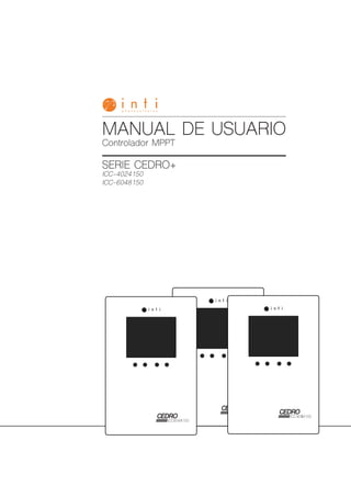
  • 1. 1 www.intipv.com MANUAL DE USUARIO CONTROLADOR CEDRO PLUS Controlador MPPT SERIE CEDRO+ ICC-4024150 ICC-6048150 MANUAL DE USUARIO 2
  • 2. 2 www.intipv.com MANUAL DE USUARIO CONTROLADOR CEDRO PLUS
  • 3. 3 www.intipv.com MANUAL DE USUARIO CONTROLADOR CEDRO PLUS INDICE INDEX 4 4 4 4 4 6 6 6 7 7 7 8 8 8 9 9 9 10 10 11 11 13 15 15 21 21 22 22 23 26 26 26 26 27 28 28 28 29 29 29 30 30 30 31 31 31 32 32 33 33 33 37 37 43 43 44 44 45
  • 4. 4 www.intipv.com MANUAL DE USUARIO CONTROLADOR CEDRO PLUS Precaución: Indica un procedimiento crítico para seguridad y operación apropiada del controlador Atención: Indica una condición potencialmente peligrosa. Sea extremadamente precavido realizando esta operación. Los siguientes símbolos son utilizados en este manual para indicar condiciones potencialmente peligrosas o indicar instrucciones de seguridad importantes. El fabricante no será responsable por daños, especialmente en la batería, causados por utilización diferente a la mencionada en este manual o si las recomendaciones del fabricante de la batería son ignoradas. El fabricante no será responsable si ha habido una reparación llevada a cabo por persona no autorizada, uso inusual, instalación inapropiada o mal diseño del sistema. Perfil MPPT El nombre completo de MPPT es Maximum Power Point Tracking (Seguimiento del Punto de Máxima Potencia). Es una forma de carga avanzada que puede detectar en tiempo real la potencia entregada por el módulo y el punto de máxima potencia en la curva I – V. Impulso de corriente En la mayoría de las condiciones, la tecnología MPPT va a impulsar la corriente de carga al seguir la fórmula Potencia de entrada de los módulos = Potencia de carga de las baterías, o sea I entrada X Vmp = I salida X V batería, se asume que la eficiencia es del 100%. Si el voltaje de los módulos fotovoltaicos es más elevado que el de la batería, entonces la corriente de carga va a ser proporcionalmente más elevada que la de los módulos. Cadenas de alta tensión módulos para interconexión a la red Una ventaja de la tecnología MPPT es la habilidad de cargar baterías con arreglos solares de un voltaje nominal más elevado. Por ejemplo, un banco de baterías de 12 V puede ser cargado con módulos con voltaje nominal muy superior a esos 12 V. Módulos normalmente utilizados para soluciones interconectadas a la red también pueden ser utilizados en estos sistemas aislados. Para calcular el Voc de una cadena de módulos se debe tener en cuenta el peor escenario posible, o sea con la temperatura más baja en la que los módulos van a operar. Los datos de Voc contra temperatura deben están disponibles en la ficha técnica de los módulos. Este controlador está basado en seguimiento del punto de máxima potencia avanzado, MPPT por sus siglas en inglés. La conversión de potencia llega a una eficiencia del 98%. Contiene son una serie de características avanzadas como: • Una combinación de algoritmos de seguimiento permite un seguimiento rápido y preciso del punto de máxima potencia. • Su tecnología MPPT innovadora permite una eficiencia de seguimiento superior al 99,9%. • Gracias a su tecnología totalmente digital su eficiencia de conversión llega al 98%. • El diseño del display permite leer fácilmente datos de operación. • Posee función de estadísticas en tiempo real. • Reconocimiento automático de voltaje de batería de 12, 24 o 48V. • Posibilidad de selección de amplia gama de baterías que incluye abierta, Gel, AGM o Litio. • Extiende vida útil de baterías gracias a su sensor remoto de temperatura. • El controlador está protegido contra sobre temperatura gracias a la función de derrateo. • Posee 4 estados de carga: MPPT, boost, ecualización y flotación. • Protección automática dual para evitar exceder la corriente y potencia de carga especificadas. • Controles de salida de carga múltiples: Siempre encendido, alumbrado público, modo definido por usuario. • Comunicación loT o Bluetooth opcional. • El controlador puede ser comunicado de forma remota vía loT/GPRS con comunicación loT. • Datos de carga mensual pueden ser calculados y mostrados con agrupación y gráficas. • Puerto RJ11 para usar RS-485 con Modbus para cumplir con necesidades de comunicación para diferentes necesidades. • Perfecto diseño térmico. • Funciones de protección totalmente automáticas para maximizar la disponibilidad de servicio. INSTRUCCIONES DE SEGURIDAD Y EXCLUSIÓN DE RESPONSABILIDAD DESCRIPCIÓN GENERAL INSTRUCCIONES DE SEGURIDAD EXCLUSIÓN DE RESPONSABILIDAD MPPT
  • 5. 5 www.intipv.com MANUAL DE USUARIO CONTROLADOR CEDRO PLUS En la gráfica se puede ver la máxima potencia que puede dar un módulo y lo que se pierde al no utilizar un controlador MPPT. Esta diferencia aumenta al aumentar la diferencia entre el Vmp del módulo y el voltaje del banco de baterías. Condiciones que limitan la efectividad del MPPT El Vmp de un módulo solar decrece a medida que la temperatura se incrementa. En clima cálido, el Vmp puede estar cerca o por debajo de la tensión de la batería. En esta situación va a haber poca o ninguna ganancia de un controlador MPPT sobre un controlador PWM. Para optimizar su efectividad y el ahorro en costos de instalación se debe usar voltajes tan elevados como sea posible ATENCIÓN: PELIGRO DE EXPLOSIÓN. Ecualización de baterías abiertas puede producir gases inflamables. Las baterías deben estar instaladas en lugares son suficiente ventilación. Carga MPPT En esta etapa, el voltaje de la batería no ha llegado al voltaje de impulso y 100% de la potencia solar es utilizada para cargar la batería. Carga de impulso Cuando la batería llega al punto de voltaje de impulso (boost), regulación a voltaje constante es utilizado para prevenir calentamiento y generación de gases en la batería. Este estado toma 120 minutos antes de cambiar a carga de flotación. Cada vez que el controlador es encendido, si no detecta sobrevoltaje o sobre descarga, la carga va a entrar en carga de impulso. Carga de flotación Después del estado de carga de impulso, el controlador va a reducir su voltaje al punto de flotación. Cuando la batería ha sido totalmente recargada, no va a haber más reacciones químicas y toda la corriente de carga es transferida a la generación de gas y calor. Entonces el controlador reduce su voltaje al estado de flotación, cargando con corriente y voltaje más pequeño. Así reduce la temperatura de la batería y reduce la generación de gases. El objetivo de este estado es introducir suficiente carga para evitar su descarga por autoconsumo y pequeñas cargas en el sistema, manteniendo toda su capacidad. En flotación las cargas pueden seguir consumiendo carga de la batería. En caso de que las cargas sean superiores a la carga recibida el sistema retornará a carga MPPT. Carga de ecualización Algunos tipos de batería se benefician de una ecualización periódica que puede revolver el electrolito, balancear el voltaje entre celdas y completar la reacción química. Durante la ecualización se incrementa el voltaje de la batería, más arriba del voltaje habitual, que gasifica el electrolito. Si se detecta que la batería ha sido sobredescargada, el controlador automáticamente lleva la batería al estado de ecualización, y la carga de ecualización durará 120 minutos. Ecualización no se lleva a cabo de forma continua para evitar gasificación y calentamiento excesivos. Voltaje superior del arreglo de módulos representa una corriente más baja para una misma potencia. Esto permite el uso de cables de menor calibre. Esto representa un ahorro en el cableado del sistema. Una ventaja sobre controladores tradicionales Controladores PWM tradicionales conectan el módulo solar directamente a la batería cuando la recargan. Esto requiere que el módulo opere a una tensión que es normalmente inferior al Voltaje de máxima potencia. In un sistema de 12V, por ejemplo, la tensión de la batería puede oscilar entre 10.8 y 15V, pero el Vmp del módulo va a ser típicamente de unos 16 o 17V. Como los controladores PWM en general no operan al Vmp de los módulos, energía es desperdiciada y no va a poder ser utilizada para cargar las baterías. CARGA DE 4 ETAPAS
  • 6. 6 www.intipv.com MANUAL DE USUARIO CONTROLADOR CEDRO PLUS DIMENSIONES ICC-4024150 ICC-6048150 Unidad: mm Unidad: mm
  • 7. 7 www.intipv.com MANUAL DE USUARIO CONTROLADOR CEDRO PLUS 1. Disipador de calor. 2. Caja plástica. 3. Display 4. Teclado. 5. Puerto RJ11 6. Sensor de temperatura. 7. Terminales de carga. 8. Terminales de batería. 9. Terminales para módulos. 1. Disipador de calor 2. Caja plástica 3. Display LED y LCD 4. Teclas MENU, OK 5. Puerto de sensor de temperatura 6. Interfaz RJ11 7. Terminales de carga 8. Terminales de batería 9. Terminales de paneles solares ESTRUCTURAYACCESORIOS ICC-4024150 ICC-6048150
  • 8. 8 www.intipv.com MANUAL DE USUARIO CONTROLADOR CEDRO PLUS SENSOR DE TEMPERATURA ACCESORIOS OPCIONALES RS485 Sensor para determinar la temperatura para compensación de temperatura para que el controlador pueda cargar la batería sin afectar su vida útil. El sensor de temperatura se conecta a través del puerto 5 (ICC-6048150) o 6 (ICC-4024150). Si el sensor no está conectado o está dañado, el controlador funciona con su temperatura interna. El controlador es suministrado con un cable de 80 mm para este sensor. Un cable más largo debe ser ordenado por separado. El controlador tiene un puerto RS485 con terminal RJ11. La interfaz RJ11 se define de la siguiente forma: Protocolo aplicable a este controlador: Protocolo de Comunicación Modbus V3.9. La interfaz RS485 de este cargador no está aislada galvánicamente y no puede ser aterrizada. No ponga en corto circuito pines no utilizados (NC). Este ícono indica que el controlador tiene función de comunicación Bluetooth. Refiérase a la aplicación Bluetooth para la operación detallada de la aplicación móvil. Favor contactar nuestro equipo de ventas para más detalles sobre la comunicación inalámbrica loT. Comunicación Bluetooth 2 opciones están disponibles: 1. BT adentro. 2. BT externo (Cyber BT) conectado al puerto RJ11. La comunicación por Bluetooth tiene las siguientes características: 1. Soporta aplicación de teléfono celular. 2. Realiza monitoreo inalámbrico del cargador solar fotovoltaico. 3. Utiliza chip Bluetooth dedicado de alto desempeño y ultra bajo consumo. 4. Adopta tecnologías Bluetooth 4.2 y BLE. 5. Alcance de hasta 10 metros. Comunicación inalámbrica para internet El controlador equipado con comunicación inalámbrica para internet tiene las siguientes características: 1. Para la función inalámbrica de internet de las cosas el controlador puede ser consultado a través de loT/GPRS. 2. Una variedad de opciones está disponible para monitoreo remoto y control en tiempo real a través de una app. 3. Monitoreo en tiempo real de voltaje fotovoltaico, corriente de carga fotovoltaica, voltaje de la batería, corriente de la batería, voltaje de cargas, corriente de cargas y otros parámetros incluyendo estatus del controlador. 4. Alarma de falla en tiempo real. 5. Cantidades de carga y descarga pueden ser contadas y mostradas por ítem y mes.
  • 9. 9 www.intipv.com MANUAL DE USUARIO CONTROLADOR CEDRO PLUS NOTAS DE INSTALACIÓN REQUERIMIENTOS DELLUGAR DE INSTALACIÓN ICC-4024150 ICC-6048150 Este controlador de carga solo debe ser usado en sistemas fotovoltaicos de acuerdo con los requerimientos dados en este manual y las especificaciones de otros componentes del sistema suministrados por sus fabricantes. Ninguna otra fuente de energía aparte de generador FV puede ser conectado al controlador FV. Los módulos FV siempre deben estar siempre desconectados antes de la instalación y ajustes del controlador de carga. Asegúrese que el interruptor, fusible o seccionador del terminal de la batería estén apagados. Las baterías almacenan una gran cantidad de energía, nunca las ponga en corto circuito. Recomendamos instalar un fusible de protección directamente sobre el terminal de batería para protección en caso de corto circuito de la batería. Las baterías pueden generar gases inflamables. Evite producir chispas, utilizando fuego o cualquier llama expuesta cerca de las baterías. Asegúrese que el cuarto con las baterías esté bien ventilado. Utilice únicamente herramientas aisladas y evite colocar objetos metálicos cerca de las baterías. Sea cuidadoso cuando trabaja con baterías. Utilice gafas de protección. Mantenga agua fresca cerca para limpiar cualquier contacto con el ácido de la batería. Nunca instale baterías sin compañía. Evite tocar o poner en corto terminales. Voltajes en algunos terminales o cables pueden ser el múltiplo del voltaje de una batería. Manténgase en piso seco. Sus manos se deben mantener secas. Utilice guantes de protección debidamente certificados. Se debe evitar que el controlador tenga contacto directo con sol o agua. Después de la instalación asegúrese de que las conexiones están apretadas apropiadamente para eliminar puntos calientes. El controlador no debe recibir radiación directa del sol ni de ninguna otra fuente de calor. Proteja el controlador de carga de polvo, suciedad o humedad. Debe ir montado en un muro vertical. El material no debe ser inflamable. Mantenga una distancia libre de 15 cm alrededor del controlador para asegurar la libre circulación de aire. No lo monte muy lejos de las baterías. Marque la posición de los hoyos del controlador FV sobre el muro, taladre 4 hoyos, inserte las clavijas, ponga el controlador en el muro con los terminales hacia abajo. PRECAUCIÓN: Favor leer todas las instrucciones y precauciones en este manual antes de proceder con la instalación. Se recomienda remover el protector plástico del display antes de la operación. INSTALACIÓN
  • 10. 10 www.intipv.com MANUAL DE USUARIO CONTROLADOR CEDRO PLUS ESPECIFICACIONES DE CABLEADO CONEXIONES Los métodos de cableado e instalación deben cumplir con los códigos eléctricos nacionales. Las especificaciones de cableado de baterías y arreglo fotovoltaico deben ser determinado de acuerdo con las corrientes nominales. Recomendamos conectar un fusible en el terminal de la batería. Los módulos FV generan corriente siempre que el sol brille sobre ellos. La corriente es proporcional a la intensidad de la luz. Incluso bajos niveles de luminosidad, estando sin carga, van a entregar el voltaje máximo, entonces es recomendable cubrir los módulos durante la instalación. Nunca toque cables no aislados, utilice herramientas aisladas y asegúrese de que la sección del conductor sea adecuada para la corriente nominal. Las conexiones se deben hacer de acuerdo con la siguiente secuencia. Advertencia: El arreglo FV puede producir voltajes de circuito abierto superiores a 100 Vdc cuando son expuestos al sol. Advertencia: Riesgo de explosión. En caso de que los terminales positivo y negativo de la batería entren en contacto, en corto circuito, riesgo de fuego o explosión puede ocurrir. Preste la mayor atención en la manipulación de baterías y circuitos relacionados. Precaución: Si no hay sensor de temperatura conectado al controlador, la temperatura indicada en el display será la temperatura interna del controlador. Si un inversor es utilizado en el sistema, conéctelo al terminal de la batería, no a la salida de carga del controlador. Paso 1: Conecte la batería Conecte los cables de la batería teniendo en cuenta la polaridad correcta a los bornes del centro del controlador. Sea cuidadoso con a polaridad. Si su sistema va a ser a 12V, asegúrese de que la batería tiene un voltaje entre 5 y 15.5 Vdc, para un sistema a 24 V, el banco de baterías debe estar entre 20 y 31 Vdc, para 48 V entre 40 y 62 Vdc. Después de esta conexión, el display debe indicar el voltaje. Paso 2: Conecte los módulos Cuando conecte los módulos, asegúrese que no estén recibiendo radiación solar. Asegúrese que el Voc de los módulos no sea superior al admisible por el controlador. Conecte los módulos con polaridad correcta al par de bornes a la izquierda del controlador. Paso 3: Conecte cargas Conecte el cable de carga con la polaridad correcta sobre el par de bornes a la derecha del controlador, con el símbolo de la lámpara. Para evitar cualquier tensión en los cables, conéctelos primero a la carga y después al controlador. Paso 4: Trabajo final Apriete todos los cables conectados al controlador y remueva todos los restos alrededor del controlador, dejando un espacio de 15 cm.
  • 11. 11 www.intipv.com MANUAL DE USUARIO CONTROLADOR CEDRO PLUS PUESTA A ATIERRA Tenga en cuenta que terminales negativos del controlador están interconectado y por lo tanto tienen el mismo potencial eléctrico. Si se necesita aterrizar, haga esto siempre con los terminales negativos. Precaución: Para sistema negativo común, como una casa rodante, se recomienda usar un controlador con negativo común, pero si tenemos un sistema con negativo común, equipo con positivo común es utilizado y el polo positivo es aterrizado, el controlador se puede dañar OPERACIÓN Estado Arreglo fotovoltaico Durante el día, no carga Durante el día, carga Noche Voltaje fotovoltaico, corriente y amperios hora La carga total en amperios hora del panel solar Batería Capacidad de la batería Voltaje de la batería (LVD programable) Corriente de la batería Estado de carga de la batería (en %) Temperatura Tipo de batería (programable) Carga Voltaje de carga (LVR programable) Corriente de carga y amperios hora Descarga total de la carga en ah Modo de carga (programable) La carga está encendida La carga está apagada Falla Indicación de falla, ver sección 6.1.4 DISPLAY LCD ICC-4024150 Ítem Ícono Descripción de estados
  • 12. 12 www.intipv.com MANUAL DE USUARIO CONTROLADOR CEDRO PLUS La carga en ah del sistema solar y de la carga de salida se apagan si hay falla en el sistema. La interfaz cicla automáticamente en la secuencia indicada: Oprima OK para examinar la interfaz: Estado Descripción Cortocircuito Carga apagada, ícono de falla en el display, ícono de carga intermitente, E1 en la pantalla LCD. Sobre corriente Carga apagada, ícono de falla en el display, ícono de carga intermitente, E2 en la pantalla LCD. Bajo voltaje Nivel de batería vacío, ícono de falla en el display, ícono de batería intermitente, E3 en la pantalla LCD. Sobre voltaje Nivel de batería lleno, ícono de falla en el display, ícono de batería intermitente, E4 en la pantalla LCD. Sobre temperatura Carga y descarga apagados, ícono de falla en el displai, ícono ºC intermitente, E5 en la pantalla LCD. Fallo en comunicación La tarjeta del display no puede obtener la data del controlador, ícono de falla en el display, E6 en la pantalla LCD. El controlador no identifica correctamente el voltaje del sistema El controlador no identifica correctamente el voltaje del sistema, ícono de falla en el display, E7 en la pantalla LCD. Ícono Indicación de fallas
  • 13. 13 www.intipv.com MANUAL DE USUARIO CONTROLADOR CEDRO PLUS DISPLAY LCD ICC-6048150 Led solar Led de carga Led de batería Led de comunicación Led Estado Función Verde (panel solar) On El panel solar está conectado, no carga Parpadeo rápido (0,1/0,1s) Carga MPPT Parpadeo (0,5/0,5s) Carga de impulso o ecualización Parpadeo lento (0,5/2s) Carga de flotación Amarillo (batería) On Estado de batería normal Off Protección de sobre voltaje Parpadeo rápido (0,1/0,1s) Protección de bajo voltaje Parpadeo lento (0,5/2s) El voltaje de la batería es bajo Rojo (carga) On La carga está encendida Off La carga está apagada Parpadeo rápido (0,1/0,1s) Protección de cortocircuito Parpadeo lento (0,5/2s) Protección de sobre temperatura Azul (comunicación) Off No hay comunicación Parpadeo rápido (0,1/0,1s) Comunicación normal Item Estado Arreglo fotovoltaico Carga Voltaje fotovoltaico Corriente fotovoltaica Amperios hora fotovoltaicos durante el día Amperios hora totales de carga del panel solar Batería Capacidad de batería Voltaje de batería (LVD programable) Corriente de batería Tipo de batería (programable) Temperatura (borrar la contraseña del dispositivo Bluetooth) Carga Voltaje de carga (LVR programable) Corriente de carga Amperios hora de carga en el día Amperios hora de descarga totales de la carga Modo carga (programable) Ícono Descripción de estados
  • 14. 14 www.intipv.com MANUAL DE USUARIO CONTROLADOR CEDRO PLUS La carga en ah del sistema solar y de la carga de salida se apagan si hay falla en el sistema. La interfaz automáticamente cicla de acuerdo con la siguiente secuencia: Presione OK para buscar la interfaz:
  • 15. 15 www.intipv.com MANUAL DE USUARIO CONTROLADOR CEDRO PLUS Cuando el ícono aparece en el display, quiere decir que los parámetros pueden ser establecidos. Presione la tecla MENU por 1s, luego el ícono va a parpadear, presione OK para cambiar de parámetro. Protección de bajo voltaje Cuando la pantalla LCD muestra el display inferior, presione la tecla MENU por 1 segundo, el ícono se presentará intermitente y puede configurar la protección de bajo voltaje del controlador: FUNCIONES DELTECLADO AJUSTE DE PARÁMETROS ICC-4024150 Estado Ícono Descripción Cortocircuito Cortocircuito Sobre corriente Sobre corriente Bajo voltaje Bajo voltaje Sobre voltaje Sobre voltaje Sobre temperatura Sobre temperatura El controlador no identifica correctamente el voltaje del sistema El controlador no identifica correctamente el voltaje del sistema Modo Operación Interfaz de búsqueda Presione OK Display estático Presione MENU y OK al mismo tiempo por 1s, la pantalla, la pantalla LCD bloqueará el interfaz. Presione de nuevo MENU y OK durante 1s para desbloquearla. Configuración de parámetros Presione la tecla MENU durante 1s para entrar en el modo de configuración cuando el ícono aparezca en el display, y salga automáticamente después de 30s. Carga on/off Cuando el controlador trabaje en modo de luminaria solar, presione la tecla MENU durante 3s para encender la carga, presione la tecla MENU de nuevo o 1 minuto después se apagará la carga. Indicación de fallas
  • 16. 16 www.intipv.com MANUAL DE USUARIO CONTROLADOR CEDRO PLUS 1. Batería de litio: el rango configurable es entre 9 y 30V, el valor predeterminado es 10,6V 2. Batería de Gel y AGM: la protección de bajo voltaje del controlador se puede dividir en dos tipos: control de voltaje de batería y control de capacidad. - Control de voltaje de batería: el rango de configuración es: 10,8-11,8V/21,6-23,6V/43,2-47,2V, los valores predeterminados son 11,2/22,4/44,8V. - Control de capacidad de batería: Reconexión por bajo voltaje Cuando la pantalla LCD muestra el display inferior, presione la tecla MENU por 1 segundo, el ícono se presentará intermitente y puede configurar la reconexión por bajo voltaje del controlador: 1. Batería de litio: el rango configurable es entre 9,6 y 31V, el valor predeterminado es 12V 2. Batería de Gel y AGM: el rango configurable es 11,4-12,8V/22,8-25,6V/45,6-51,2V, el valor predeterminado es 12/24/48V. Borrar la contraseña de bluetooth El valor de recuperación por bajo voltaje (LVR) debe ser mayor que el valor de protección por bajo voltaje (LVD) en por lo menos 0,6/1,2/2,4V. Pantalla Rango de protección de bajo voltaje 11,0-11,6V/22,0-23,2V/44,0-46,4V 11,1-11,7V/22,2-23,4V/44,4-46,8V 11,2-11,8V/22,4-23,6V/44,8-47,2V 11,4-11,9V/22,8-23,8V/45,6-47,6V 11,6-12,0V/23,2-24,0V/46,4-48,0V
  • 17. 17 www.intipv.com MANUAL DE USUARIO CONTROLADOR CEDRO PLUS Cuando la pantalla LCD se muestra como el ícono izquierdo, presione la techa MENU durante 1 segundo, el ícono se presentará intermitente y puede presionar el botón OK para borrar la contraseña de Bluetooth del dispositivo configurada por la aplicación del móvil. Cuando la pantalla LCD muestra el display superior, presione la tecla MENU por 1 segundo, el ícono se presentará intermitente y puede configurar el tipo de batería así: 1. Parámetros de voltaje de carga para baterías líquidas, GEL y AGM: Al elegir este tipo de baterías, los parámetros de carga de voltaje de boost, ecualización y flotación pueden configurarse por una aplicación móvil o RS485. El rango de los parámetros se muestra a continuación. Los siguientes parámetros de voltaje son para condiciones estándar en sistemas de 25ºC @12V, para sistemas de 24, 48V los valores mostrados son multiplicados por 2 y por 4. NOTA: (Voltaje de recuperación de sobrecarga + 1,5V) ≥ Voltaje de protección de sobrecarga en litio ≥ (Voltaje de recuperación de sobrecarga + 0,2V) Precaución: la precisión requerida del BMS debe ser al menos 0,2V. Si la tolerancia es mayor de 0,2V se puede afectar la respuesta de garantía. 2. Parámetros de voltaje de carga de baterías de litio: Al elegir este tipo de baterías, la protección de sobre voltaje y voltaje de recuperación de sobrecarga de las baterías de litio se pueden configurar por la aplicación móvil o RS485. Rango de voltaje de protección de sobrecarga en litio: 10,0-32,0V, el valor predeterminado es 14,4V. Rango de voltaje de recuperación de sobrecarga en litio: 9,2-31,8V, el valor predeterminado es 14,0V. Tipo de batería Pantalla Tipo de batería GEL (predeterminado) Líquido AGM Litio Estado de carga Boost Ecualización Flotación Rango de voltaje de carga 14,0-14,8V 14,0-15,0V 13,0-14,5V Voltaje de carga predeterminado 14,5V 14,8V 13,7V
  • 18. 18 www.intipv.com MANUAL DE USUARIO CONTROLADOR CEDRO PLUS Modo de carga Cuando la pantalla LCD muestra el display superior, presione la tecla MENU por 1 segundo, el ícono se presentará intermitente y puede configurar el modo de carga: Si el controlador apaga la carga debido a la protección por bajo voltaje, protección de sobre corriente, protección de cortocircuito o protección de sobre temperatura, la carga se encenderá automáticamente cuando el controlador recupera su estado de protección. Presionando el botón MENU se puede activar la función de la tecla, incluso durante los 4 tipos de estado de protección superiores. 1. Modo siempre encendido: cuando el controlador se configura el modo encendido, no importa el estado de carga o descarga, la carga siempre está encendida (excepto en estado de protección) 2. Función de luminarias solares: cuando la función se configura de atardecer a amanecer o modo de tarde, el umbral de voltaje de día/noche y el tiempo de retraso se puede configurar con la APP del móvil o con RS485, y así la carga se puede encender y apagar durante el día de carga. - Voltaje umbral día/noche: el controlador reconoce el día y la noche basado en el voltaje de circuito abierto del panel solar. Este umbral de voltaje día/noche puede modificarse de acuerdo con las condiciones de luz local y el arreglo usado de paneles solares. Rango configurable de voltaje día/noche para baterías de litio: 3,0-20,0V, valor predeterminado 8,0V. Rango configurable de voltaje día/noche para baterías líquidas, GEL, AGM: 3,0-10V/6,0-20V/12-40V, valor predeterminado 8/16/32V. - Tiempo de retraso día/noche: en la noche, cuando el voltaje de circuito abierto del panel solar alcanza el voltaje configurado, puede ajustar el tiempo de retraso día/noche para encender la carga algún tiempo después. Rango configurable de tiempo de retraso día/noche: 0-30min, valor predeterminado 0min. - Función de prueba: cuando el controlador trabaja desde el atardecer hasta el amanecer o en modo tarde, presione la tecla MENU por 3 segundos para encender la carga. Presione la techa MENU de nuevo o la carga se apagará automáticamente después de 1 minuto. Si el controlador opera siempre en modo encendido, la función de prueba no funciona. - Modo definido por usuario: si se selecciona el modo de carga en “USE”, puede cambiar la salida de carga manualmente de encendido a apagado presionando la tecla MENU. El estado predeterminado de encendido de la carga en modo manual puede cambiarse a través de la APP en el móvil o a través de RS485. Al mismo tiempo, la salida de la carga puede ser encendida o apagada. Pantalla Modo de carga Siempre modo encendido: la salida de carga siempre está encendida. Modo de atardecer a amanecer: la salida de carga se enciende entre el atardecer y el amanecer. Modo de tarde: la salida de carga se enciende durante 2 a 9 horas después del atardecer. Modo manual: la salida de carga puede encenderse y apagarse de modo manual presionando la tecla MENU.
  • 19. 19 www.intipv.com MANUAL DE USUARIO CONTROLADOR CEDRO PLUS Protección de bajo voltaje Reconexión por bajo voltaje Borrar la contraseña de bluetooth Tipo de batería El valor de recuperación por bajo voltaje (LVR) debe ser mayor que el valor de protección por bajo voltaje (LVD) en por lo menos 0,6/1,2/2,4/4,8V. Cuando el ícono aparece en el display, quiere decir que los parámetros pueden ser establecidos. Presione la tecla MENU por 1s, luego el ícono va a parpadear, presione OK para cambiar de parámetro; cuando termine la configuración, puede esperar 30 segundos para salir del modo configuración automáticamente, o puede presionar el MENU para salir de este modo. Cuando la pantalla LCD se muestre como la figura superior, presione la tecla MENU por 1s y el ícono parpadeará, ahora puede cambiar la protección de bajo voltaje del controlador. 1. Batería de litio: el rango de configuración es entre 9,0 y 60,0V (predeterminado 21,0V) 2. Batería líquida, Gel y AGM: el rango de configuración es 10,8-11,8V/21,6-23,6V/32,4-35,4/43,3-47,2V (predeterminado 11,2/22,4/33,6/44,8V) Cuando la pantalla LCD se muestre como la figura superior, presione la tecla MENU por 1s, el ícono parpadeará, ahora puede cambiar la reconexión por bajo voltaje del controlador. 1. Batería de litio: el rango de configuración es entre 9,6 y 62,0V (predeterminado 22,4V) 2. Batería líquida, Gel y AGM: el rango de configuración es 11,4-12,8V/22,8-25,6V/34,2-38,4/45,6-51,2V (predeterminado 12/24/36/48V) Cuando la pantalla LCD se muestra como el ícono superior, presione la techa MENU durante 1 segundo, el ícono se presentará intermitente y puede presionar el botón OK para borrar la contraseña de Bluetooth del dispositivo configurada por la aplicación del móvil Cuando la pantalla LCD se muestra como el ícono superior, presione la techa MENU por 1s, el ícono se presentará intermitente y puede ajustar el tipo de batería así Pantalla Tipo de batería GEL (predeterminado) Líquido AGM Litio ICC-6048150
  • 20. 20 www.intipv.com MANUAL DE USUARIO CONTROLADOR CEDRO PLUS 1. Parámetros de voltaje de carga para baterías líquidas, GEL y AGM: Al elegir este tipo de baterías, los parámetros de carga de voltaje de boost, ecualización y flotación pueden configurarse por una aplicación móvil o RS485. El rango de los parámetros se muestra a continuación. Los siguientes parámetros de voltaje son para condiciones estándar en sistemas de 25ºC @12V, para sistemas de 24, 36 y 48V los valores mostrados son multiplicados por 2, 3 y por 4. Modo de carga NOTA: (Voltaje de recuperación de sobrecarga + 1,5V) ≥ Voltaje de protección de sobrecarga en litio ≥ (Voltaje de recuperación de sobrecarga + 0,2V) Precaución: la precisión requerida del BMS debe ser al menos 0,2V. Si la tolerancia es mayor de 0,2V se puede afectar la respuesta de garantía. 2. Parámetros de voltaje de carga de baterías de litio: Al elegir este tipo de baterías, la protección de sobre voltaje y voltaje de recuperación de sobrecarga de las baterías de litio se pueden configurar por la aplicación móvil o RS485. Rango de voltaje de protección de sobrecarga en litio: 10,0-64,0V, el valor predeterminado es 29,4V. Rango de voltaje de recuperación de sobrecarga en litio: 9,2-63,8V, el valor predeterminado es 28,7V. 1. Modo siempre encendido: cuando el controlador se configura el modo encendido, no importa el estado de carga o descarga, la carga siempre está encendida (excepto en estado de protección) 2. Función de luminarias solares: cuando la función se configura de atardecer a amanecer o modo de tarde, el umbral de voltaje de día/noche y el tiempo de retraso se puede configurar con la APP del móvil o con RS485, y así la carga se puede encender y apagar durante el día de carga. - Voltaje umbral día/noche: el controlador reconoce el día y la noche basado en el voltaje de circuito abierto del panel solar. Este umbral de voltaje día/noche puede modificarse de acuerdo con las condiciones de luz local y el arreglo usado de paneles solares. Rango configurable de voltaje día/noche: 3,0-10,0/6,0-20,0/9,0-30,0/12,0-40,0V (predeterminado: 8/16/24/32V) - Tiempo de retraso día/noche: en la noche, cuando el voltaje de circuito abierto del panel solar alcanza el voltaje configurado, puede ajustar el tiempo de retraso día/noche para encender la carga algún tiempo después. Rango configurable de tiempo de retraso día/noche: 0-30min, valor predeterminado 0min. - Función de prueba: cuando el controlador trabaja desde el atardecer hasta el amanecer o en modo tarde, presione la tecla MENU por 3 segundos para encender la carga. Presione la techa MENU de nuevo o la carga se apagará automáticamente después de 1 minuto. Cuando la pantalla LCD muestra el display superior, presione la tecla MENU por 1 segundo, el ícono se presentará intermitente y puede configurar el modo de carga así: Si el controlador apaga la carga debido a la protección por bajo voltaje, protección de sobre corriente, protección de cortocircuito o protección de sobre temperatura, la carga se encenderá automáticamente cuando el controlador recupera su estado de protección. Presionando el botón MENU se puede activar la función de la tecla, incluso durante los 4 tipos de estado de protección superiores. Estado de carga Boost Ecualización Flotación Rango de voltaje de carga 14,0-14,8V 14,0-15,0V 13,0-14,5V Voltaje de carga predeterminado 14,5V 14,8V 13,7V Pantalla Modo de carga Siempre modo encendido: la salida de carga siempre está encendida. Modo de atardecer a amanecer: la salida de carga se enciende entre el atardecer y el amanecer. Modo de tarde: la salida de carga se enciende durante 2 a 9 horas después del atardecer. Modo manual: la salida de carga puede encenderse y apagarse de modo manual presionando la tecla MENU. - Modo definido por usuario: si se selecciona el modo de carga en “USE”, puede cambiar la salida de carga manualmente de encendido a apagado presionando la tecla MENU. El estado predeterminado de encendido de la carga en modo manual puede cambiarse a través de la APP en el móvil o a través de RS485. Al mismo tiempo, la salida de la carga puede ser encendida o apagada.
  • 21. 21 www.intipv.com MANUAL DE USUARIO CONTROLADOR CEDRO PLUS RESOLUCIÓN DE PROBLEMAS, PROTECCIONES Y MANTENIMIENTO RESOLUCIÓN DE PROBLEMAS - ICC-4024150 RESOLUCIÓN DE PROBLEMAS - ICC-6048150 Fallas Causa Resolución de problema Cortocircuito Apague todas las cargas, remueva el cortocircuito, la carga se reconectará automáticamente luego de 1 minuto. Sobre corriente Reduzca la carga, el controlador comenzará a trabajar de nuevo luego de 1 minuto. El voltaje de la batería es muy bajo La carga se reconectará cuando la batería se recargue. El voltaje de la batería es muy alto Verifique si hay otras fuentes de sobrecarga. De lo contrario, el controlador está dañado. Sobre temperatura Luego de disminución en la temperatura, el controlador trabaja- rá normalmente. Falla de comunicación Reconecte después de desconectar la batería durante 1 minuto y luego reconecte el dispositivo bluetooth. El voltaje de la batería es anormal al arranque Cargue o descargue la batería para que el voltaje de la batería entre dentro de los tangos normales de operación (8,5-15,5V/20-31V/40-62V) La batería no puede cargarse durante las horas del día. Falla en el panel solar o conexión invertida Chequee los cables de conexión de los paneles. Fallas Causa Resolución de problema Cortocircuito Apague todas las cargas, remueva el cortocircuito, la carga se reconectará automáticamente luego de 1 minuto. Sobre corriente Reduzca la carga, el controlador comenzará a trabajar de nuevo luego de 1 minuto. El voltaje de la batería es muy bajo La carga se reconectará cuando la batería se recargue. El voltaje de la batería es muy alto Verifique si hay otras fuentes de sobrecarga. De lo contrario, el controlador está dañado. Sobre temperatura Luego de disminución en la temperatura, el controlador trabaja- rá normalmente. El voltaje de la batería es anormal al arranque Cargue o descargue la batería para que el voltaje de la batería entre dentro de los tangos normales de operación (8,5-15,5V/20-31V/31-42V/40-62V)
  • 22. 22 www.intipv.com MANUAL DE USUARIO CONTROLADOR CEDRO PLUS PROTECCIÓN MANTENIMIENTO Protección Descripción Sobre corriente fotovoltaica El controlador limitará la potencia de carga al nivel nominal. Arreglos de paneles sobre dimensionados no operarán al máximo punto de potencia. Cortocircuito fotovoltaico Cuando hay cortocircuito fotovoltaico, el controlador dejará de carga. Remueva el cortocircuito para regresar a la operación normal. Polaridad inversa fotovoltaica Protección total contra polaridad reversa fotovoltaica, no hay daño en el controlador. Corrija la conexión y vuelva a la operación normal. Polaridad inversa de batería Protección total contra polaridad inversa de la batería, no hay daño en el controlador. Corrija la conexión y vuelva a la operación normal. Sobre voltaje de batería Si hay otras fuentes de energía que carguen la batería y esta exceda los 15,8/31,3/46,8/62,3V el controlador dejará de cargar para proteger la batería de daños de sobrecarga. El voltaje de protección de sobrecarga para baterías de litio equivale al voltaje objetivo 0,2V. Sobre descarga de batería Cuando cae el voltaje de la batería a un bajo voltaje de desconexión, el controlador dejará de descargar para proteger la batería de daño de sobre descarga. Protección de corriente de sobrecarga Si la corriente de la carga excede la máxima corriente de carga por 1,25 veces, el controlador desconectará la carga. Protección de cortocircuito de carga Una vez que hay un cortocircuito en carga, se encenderá esta protección. Protección de sobre temperatura El controlador detecta temperatura interna a través de un sensor en el interior del equipo, cuando la temperatura excede el valor establecido, la corriente de carga decrecerá, y consecuentemente, la temperatura del controlador; si la temperatura del controlador aumentara y se acercara al umbral de protección de sobre temperatura, el controlador dejaría de funcionar y continuaría luego de una disminución de temperatura a un nivel aceptable. Sensor de temperatura remoto dañado Si el sensor de temperatura se daña o es cortocircuitado, el controlador cargará o descargará a la temperatura interna par aprevenir daño en la batería de sobrecargarse o sobre descargarse. Para un funcionamiento eficiente del sistema, se recomienda seguir las siguientes tareas de inspección y mantenimiento al menos dos veces al año: - Asegúrese de que el flujo de aire no esté bloqueado alrededor del controlador. Limpie cualquier sucio o elemento en el disipador. - Chequee todos los cables desnudos para asegurarse que el aislamiento no se dañe. Repare o reemplace los cables si es necesario. - Asegure los tornillos de los terminales al torque indicado; inspeccione si hay tornillos sueltos, rotos o conexiones de cable quemadas. - Chequee y confirme que la pantalla LCD es consistente con la requerida. Preste atención de cualquier alarma o error de indicación. Tome acciones correctivas de ser necesario. - Asegúrese que todos los componentes del sistema están correctamente conectados a tierra. - Chequee si hay signos de corrosión en los terminales, aislamiento dañado, aumento de temperatura o signos de decoloración. - Chequee si hay sucio, nidos de insectos o algún signo de corrosión. Implemente las correcciones necesarias tan pronto como sea posible. Precaución Riesgo de shock eléctrico. Asegúrese que el sistema no esté energizado antes de tomar en cuenta las medidas anteriores y luego siga las correspondientes operaciones e inspecciones
  • 23. 23 www.intipv.com MANUAL DE USUARIO CONTROLADOR CEDRO PLUS INFORMACIÓN TÉCNICA ítem ICC-4024150 ICC-6048150 Parámetros de la batería Máxima corriente de carga 40A 60A Voltaje del sistema Reconocimiento automático 24/48V Reconocimiento automático 12/24/36 /48V Voltaje de carga MPPT Antes del impulso o estado de ecualización Voltaje de impulso 28,0-29,6V/56,0-59,2V @25ºC (predeterminado 29,0/58,0V) 14-14,8V/28,0-29,6V/42-44,4V/56,0- 59,2V @25ºC (predeterminado 14,5/29,0/43,5/58,0V) Voltaje de ecualización 28,0-30,0V/56,0-60,0V @25ºC (predeterminado 29,6/59,2V) 14,0-15,0V/28,0-30,0V/42-45/56,0- 60,0V @25ºC (predeterminado 14,8/29,6/44,4/59,2V) Voltaje de flotación 26,0-29,0V/52,0-58,0V @25ºC (predeterminado 27,4/54,8V) 13,0-14,5V/28,0-30,0V/42-45V/56- 60V @25ºC (predeterminado 13,7/27,4/41,1/54,8V) Desconexión por bajo voltaje 21,6-23,6V/43,2-47,2V, SOC1-5 (predeterminado: 22,4/44,8V) 10,8-11,8/21,6-23,6V/32,4-35,4/43,2- 47,2V, SOC1-5 (predeterminado: 11,2/22,4/33,6/44,8V) Reconexión por bajo voltaje 22,8-25,6V/45,6-51,2V (predeterminado: 24,0/48,0V) 11,4-12,8V/22,8-25,6V/34,2- 38,4V/45,6-51,2V (predeterminado: 12,0/24,0/36,0/48,0V) Protección de sobrecarga 31,3/62,3V 15,8/31,3/46,8/62,3V Compensación de temperatura -4,17mV/K/celda (impulso, ecualización) -3,33mV/K/celda (flotación) Voltaje de carga objetivo 20,0-64,0V (litio, predeterminado:29,4V) 10,0-64,0V (litio, predeterminado:29,4V) Voltaje de carga de recuperación 18,2-63,8V (litio, predeterminado:28,7V) 9,2-63,8V (litio, predeterminado:28,7V) Desconexión por bajo voltaje 18,0-60,0V (litio, predeterminado:21,0V) 9,0-60,0V (litio, predeterminado:21,0V) Reconexión por bajo voltaje 18,6-62,0V (litio, predeterminado:22,4V) 9,6-62,0V (litio, predeterminado:22,4V) Tipo de batería Gel, AGM, líquido, litio (predeterminado: Gel) Máximo voltaje en terminal de batería 65V Parámetros de paneles Máximo voltaje en terminales fotovol- taicos 150V (25ºC) Máxima potencia de entrada 1000/2000W 750/1500/2250/3000W Umbral día/noche 6,0-40,0V (predeterminado: 16,0/32,0V) 3,0-10,0/6,0-20,0/9,0-30,0/12,0-40,0V (predeterminado (8,0/16,0/24,0/32,0V) Tiempo de retraso día/noche 0-30min (predeterminado: 0min) Rango MPPT (Voltaje de batería + 1,0V) – Voc*0,9 Carga Corriente de carga 30A Modo de carga Siempre encendido, luminaria, definido por el usuario Parámetros del sistema Máxima eficiencia de seguimiento >99,9% Máxima conversión de carga 98,7% 98,0% Dimensiones (mm) 189*255*89 262,5*186,5*97,5 Peso 2,5kg 3kg Autoconsumo ≤8mA ≤16mA (12V); ≤12Ma (24,36,48V) Comunicación RS485 (interfaz RJ11) Opcional IoT, Cyber-BT Tierra Negativo común Terminales de potencia 6AWG (16mm2) Temperatura ambiente -20 a +55ºC Temperatura de almacenamiento -25 a 80ºC Humedad ambiente 0 -100%RH Grado de protección IP32 Máxima altitud 4000m
  • 24. 24 www.intipv.com MANUAL DE USUARIO CONTROLADOR CEDRO PLUS CURVAS DE EFICIENCIADE CONVERSIÓN 24V: con voltaje MPP de módulo solar 36V/54V/72V 24V: con voltaje MPP de módulo solar 34V/51V/68V 48V: con voltaje MPP de módulo solar 72V/90V 48V: con voltaje MPP de módulo solar 68V/85V ICC-4024150 ICC-6048150
  • 25. 25 www.intipv.com MANUAL DE USUARIO CONTROLADOR CEDRO PLUS
  • 26. 26 www.intipv.com MANUAL DE USUARIO CONTROLADOR CEDRO PLUS WARNING: Indicates a potentially dangerous condition. Use extreme caution when performing this task CAUTION: Indicates a critical procedure for safe and proper operation of the controller. The following symbols are used throughout this manual to indicate potentially dangerous conditions or mark important safety instructions. Please take care when meeting these symbols The manufacturer shall not be liable for damages, especially on the battery, caused by use other than as intended or as mentioned in this manual or if the recommendations of the battery manufacturer are neglected. The manufacturer shall not be liable if there has been service or repair carried out by any unauthorized person, unusual use, wrong installation, or bad system design. MPPT Profile The full name of the MPPT is maximum power point tracking. It is an advanced charging way which could detect the real-time power of the solar module and the maximum point of the I-V curve that make the highest battery charging efficiency. Current boost Under most conditions, MPPT technology will “boost” the solar charge current through the solar module input power formula where MPPT Charging: Power Into the controller (Pmax)=Power out of the controller (Pout), i.e., Iin x Vmp = Iout x Vout, assuming 100% efficiency. If the solar module’s maximum power voltage (Vmp) is greater than the battery voltage, the battery current must be proportionally greater than the solar input current so that input and output power are balanced. The greater the difference between the Vmp and battery voltage, the greater the current boost. High Voltage Strings and Grid-Tie Modules Another benefit of MPPT technology is the ability to charge batteries with solar arrays of higher nominal voltages. For example, a 12 Volt battery bank may be charged with a 12-, 24-, 36-, or 48-Volt nominal off-grid solar array. Grid-tie solar modules may also be used as long as the solar array open circuit voltage (Voc) rating will not exceed the maximum input voltage rating at worst-case (coldest) module temperature. The solar module documentation should provide Voc vs. temperature data. This series solar controller is based on an advanced maximum power point tracking (MPPT) technology developed, dedicated to the solar system, the controller conversion efficiency up to 98%. It has several outstanding features, such as: • A combination of multiple tracking algorithms enables tracking the maximum power point quickly and accurately. • Innovative Max Power Point Tracking (MPPT) technology, tracking efficiency >99.9%. • Full digital technology, high charge conversion efficiency up to 98%. • LCD display design read operating data and working condition easily. • Real-time energy statistics function. • 12/24/48V automatic recognition. • Flexible System battery selection: Liquid, Gel, AGM and Lithium. • Extends battery life through accurate remote temperature sensor. • Controller is protected against over-temperature due to built-in power reduction function. • Four stages battery charging process: MPPT, boost, equalization, float. • Dual automatic protection to avoid exceeding the rated charging power and current. • Multiple load control modes: Always on, Street lamp, User-defined Mode. • Two USB interfaces (only -EU model). • IoT wireless communication or Bluetooth communication functions optional. • With the wireless communication function of the IoT, the controller can be connected remotely through IoT/GPRS. • Monthly charging data can be calculated and displayed by grouping and graphs. • Based RS-485 standard Modbus protocol with RJ11 interface to maximize the communication needs of different occasions. • Perfect EMC & thermal design. • Full automatic electronic protect function for increased charge controller availability. SAFE INSTRUCTIONSAND RESPONSIBILITY LIABILITY OVERVIEW SAFETY INSTRUCTIONS LIABILITY EXCLUSION MPPT
  • 27. 27 www.intipv.com MANUAL DE USUARIO CONTROLADOR CEDRO PLUS In the above graph it can be distinguished the maximum power that a solar module can generate, and the amount of Energy wasted while not using MPPT controllers. Conditions That Limit the Effectiveness of MPPT The Vmp of a solar module decreases as the temperature of the module increases. In very hot weather, the Vmp may be close or even less than battery voltage. In this situation, there will be very little or no MPPT gain compared to traditional controllers. However, systems with modules of higher nominal voltage than the battery bank will always have an array Vmp greater than battery voltage. WARNING: RISK OF EXPLOSION! Equalizing flooded battery can produce explosive gases, so well ventilation of battery box is necessary. MPPT charge In this stage, the battery voltage has not yet reached boost voltage and 100% of available solar power is used to recharge the battery. Boost charge When the battery has recharged to the boost voltage setpoint, constant-voltage regulation is used to prevent heating and excessive battery gassing. The Boost stage remains 120 minutes and then goes to Float Charge. Every time when the controller is powered on, if it detects neither over discharged nor overvoltage, the charging will enter boost charging stage. Float charge After the Boost voltage stage, the controller will reduce the battery voltage to Float voltage setpoint. When the battery is fully recharged, there will be no more chemical reactions and all the charge current transmits into heat and gas at this time. Then the controller reduces the voltage to the floating stage, charging with a smaller voltage and current. It will reduce the temperature of battery and prevent the gassing, also charging the battery slightly at the same time. The purpose of Float stage is to offset the power consumption caused by self-consumption and small loads in the whole system, while maintaining full battery storage capacity. In Float stage, loads can continue to draw power from the battery. If the system load(s) exceed the solar charge current, the system will continue charging as MPPT. Equalization charge Certain types of batteries benefit from periodic equalizing charge, which can stir the electrolyte, balance battery voltage and complete chemical reaction. Equalizing charge increases the battery voltage, higher than the standard complement voltage, which gasifies the battery electrolyte. If it detects that the battery is being over discharged, the solar controller will automatically turn the battery to equalization charging stage, and the equalization charging will be 120mins. Equalizing charge and boost charge are not carried out constantly in a full charge process to avoid too much gas precipitation or overheating of battery. MPPT FOUR CHARGING STAGE Higher solar input voltage results in lower solar input current for a given input power. High voltage solar input strings allow for smaller gauge solar wiring. This is especially helpful and economical for systems with long wiring runs between the controller and the solar array. An Advantage Over Traditional Controllers Traditional PWM controllers connect the solar module directly to the battery when recharging. This requires that the solar module operates in a voltage range that is usually below the module’s Vmp. In a 12 Volt system for example, the battery voltage may range from 10.8-15 Vdc, but the module’s Vmp is typically around 16 or 17V. Because traditional controllers do not always operate at the Vmp of the solar array, energy is wasted that could otherwise be used to charge the battery and power system loads. The greater the difference between battery voltage and the Vmp of the module, the more energy is wasted.
  • 28. 28 www.intipv.com MANUAL DE USUARIO CONTROLADOR CEDRO PLUS DIMENSIONS ICC-4024150 ICC-6048150 Unit: mm Unit: mm
  • 29. 29 www.intipv.com MANUAL DE USUARIO CONTROLADOR CEDRO PLUS 1. Heat sink. 2. Plastic case. 3. LCD display. 4. Keyboard: MENU, OK. 5. RJ11 port. 6. Temperature sensor port. 7. Load terminals. 8. Battery terminals. 9. Solar module terminals. 1. Heat sink. 2. Plastic case. 3. LCD display. 4. Keyboard: MENU, OK. 5 Temperature sensor port. 6. RJ11 interface. 7. Load terminals. 8. Battery terminals. 9. Solar module terminals. STRUCTUREANDACCESORIES ICC-2440150 ICC-6048150
  • 30. 30 www.intipv.com MANUAL DE USUARIO CONTROLADOR CEDRO PLUS TEMPERATURE SENSOR OPTIONALACCESSORIES RS485 To collect battery temperature data for temperature compensation so the controller can accurately charge the battery. The temperature sensor is connected via interface 6 (ICC-6048150) and interface 5 (ICC-4024150). If the external temperature sensor is not connected or damaged, the controller defaults to the internal temperature information. The controller is shipped with an 80 mm long cable temperature sensor. Should a sensor with a longer cable be required than this needs to be ordered separately. The charger is equipped with a RS485 port with RJ11 sockets, the RJ11 interface is defined as follows: Protocol applicable to this controller: Modbus Communication Protocol V3.9. The RS485 interface on this charger is not galvanically isolated and cannot be grounded. Do not short circuit unused pin (Note NC). This icon in this specification indicates that this solar controller has Bluetooth communication function. Refer to Bluetooth APP instructions for detailed operation of mobile APP Please contact our Sales Team for more details about the IoT wireless communication. Bluetooth communication 2 options are available: 1. BT inside. 2. BT external (Cyber-BT), and connected via RJ11 connector. Bluetooth communication has the following characteristics: 1. Support mobile phone App. 2. Realizes wireless monitoring function of PV charge controller. 3.Use high performance, ultra-low power consumption Bluetooth dedicated chip. 4. Adopt Bluetooth 4.2 and BLE technology. 5. Communication distance up to 10m. Internet Wireless communication The controller equipped with Internet wireless communication capability has the following characteristics: 1. For the wireless Internet of Things communication functionality, the controller can be remotely accessed through IoT/GPRS. 2. A variety of options are available for remote monitoring and real-time control through App /PC program. 3. Real-time monitoring of PV voltage, PV charging current, battery voltage, battery current, load voltage, load current and other system parameters as well as charge controller status. 4. Real-time automatic fault alarm. 5. Charging and discharging quantities can be counted and displayed by item grouping and month.
  • 31. 31 www.intipv.com MANUAL DE USUARIO CONTROLADOR CEDRO PLUS NSTALLATION NOTES MOUNTING LOCATION REQUIREMENTS ICC-4024150 ICC-6048150 This charge controller must only be used in PV systems in accordance with requirements given in this user manual and the specifications of other system components provided by their manufacturers. No energy source other than a PV generator may be connected to the PV charge controller referred herein. PV-modules must always be disconnected prior to the installation and adjustments of the charge controller; Make sure the circuit breaker, fuse or disconnects of battery terminal are turned off. Double check whether battery voltage meets the voltage range of Charge Controller. Batteries store a large amount of energy, never short circuit a battery under any circumstances. We strongly recommend connecting a protection fuse directly to the battery terminal for protection in case of short circuiting the battery. Batteries can produce flammable gases. Avoid provoking any sparks, using fire or any exposed flame close to any batteries, ever. Make sure that the battery room is well ventilated to disperse any gases. Only use insulated tools and avoid placing (any) metal objects near/close to batteries. Be extremely cautious when working with batteries. Wear eye protection. Have fresh water available to immediately wash and clean any contact with battery acid. Get immediately medical aid in case of any hazard that may occur. Never install/handle with batteries alone. Avoid touching or short-circuiting wires or terminals. Be aware that voltages on given system components, terminals or wires can be a multiple of battery voltage. Only use insulated tools, stand on dry ground, and keep your hands always dry and protected by proper (approved) electrician gloves when working on PV-Systems. Prevent any water, ever, from penetrating the controller, outdoor installation must avoid any direct sunlight and penetration of any water (e.g., rain) and humidity. After installation make sure that all connections are properly tighten, eliminate any electrical loose connections to eliminate any hot electrical connection spots. Do not subject the PV charge controller to direct sunlight or any other heat sources. Protect the PV charge controller from any dust, dirt, and moisture. Mount it flat to a vertical wall. Must be a non-flammable material. Maintain a minimum clearance of 15 cm below and around the controller to ensure unhindered air circulation. Mount the PV charge controller not too far from the batteries (for accurate voltage sensing least lessening). Mark the position of the PV charge controller fastening holes on the wall, drill 4 holes and insert dowels, fasten the PV charge controller to the wall with the cable openings facing downwards. CAUTION: PLEASE READ ALL INSTRUCTIONS AND PRECAUTIONS IN THE MANUAL BEFORE PROCEEDING WITH THE INSTALLATION! IT IS RECOMMENDED TO REMOVE THE PROTECTIVE FILM COVER FROM THE LCD SCREEN BEFORE OPERATION INSTALLATION
  • 32. 32 www.intipv.com MANUAL DE USUARIO CONTROLADOR CEDRO PLUS WIRING SPECIFICATIONS CONNECTION Wiring and installation methods must comply with national and local electrical code/specifications. The wiring specifications of the PV-system battery must be selected according to rated currents. We strongly recommend connecting a fuse directly to the battery terminal to protect from any short circuit in the battery circuit. PV-modules generate current whenever light shines on them. The generated current is directly proportional to the light intensity. Even low levels of light will deliver the PV-Modules no load, full voltage. It is thus utterly advisable to protect PV-modules from any incident light during installation; Never touch uninsulated cables (ends), only use electric insulated tools, and make sure that the wire cross section is adequate for the PV module operating currents. Connections must always be conducted in the sequence as described below: WARNING: The PV-module/array can produce open-circuit voltages more than 100 Vdc when exposed to sunlight WARNING: Risk of explosion! In case the battery’s positive and negative terminals or leads get ever in touch, i.e., short-circuited, a fire or explosion hazard might get triggered. Always pay maximum when handling batteries and related circuits CAUTION: If no temperature sensor is connected to the controller, the battery temperature value will display the internal temperature. If a power inverter is used the system, directly connect the inverter to the battery. Do not connect it to the controller’s load terminals. First step: connect the battery. Connect the battery cables observing the correct polarity to the center pair of terminals (make sure you identify the battery marking/symbol on the controller casing!) of the PV charge controller. Pay greatest attention to polarity. Never, ever invert the plus+ and minus- poles). Should your system be nominal 12 Vdc, make sure the battery voltage is between the 5.0 and 15.5 Vdc voltage range; for 24 Vdc nominal voltage, the battery voltage should be within the 20.0 to 31.0 Vdc range; for 48 Vdc nominal voltage, the battery voltage should be within the 40.0 to 62.0Vdc. If the polarity is correct, the LCD on the controller will begin to display those. Second step: Connect the solar modules. When connecting the PV-Module make sure to cover it from incident sun light. Double check the PV-Module will not exceed the maximum permissible input current of the Charge Controller (please refer to the section Technical Data). Connect the solar module connection cable to the correct polarity of the left pair of terminals on the solar charge controller (with the solar module symbol). Third step: Connect the loads. Connect the load cable with the correct polarity of the right-hand side pair of terminals on the solar charge controller (with the lamp symbol). To avoid the presence of any tension on the cable/wires, please connect these first to the load before connecting them to the charge controller. Fourth step: Final work Tighten all cables connected to the controller and remove all the remains around the controller (leaving a void of minimum 15 cm).
  • 33. 33 www.intipv.com MANUAL DE USUARIO CONTROLADOR CEDRO PLUS GROUNDING Be aware that the negative terminals of controller are interconnected and therefore bear the same electrical potential. If any grounding is required, always do this on the negative wires/terminals. CAUTION: For common-negative system, such as motorhome, it is recommended to use a common-negative controller; but if in a common-negative system, some common-positive equipment is used, and the positive pole is grounded, the controller may get damaged. OPERATION Item Status PV array Daytime, not charging. Daytime, charging. Night. PV voltage current and ampere hours. The total charge ampere hours of the solar panel. Battery Battery capacity. Battery voltage (Programmable LVD). Battery current. Battery state of charge (in %). Temperature (Clear Bluetooth Device Password). Battery type (Programmable). Load Load voltage (Programmable LVR). Load current and ampere hours. The total discharge ampere hours of the load. Load mode (Programmable). The load is on. The load is off. Failure Fault indication, see 6.1.4. DISPLAY LCD ICC-4024150 Status description Icon
  • 34. 34 www.intipv.com MANUAL DE USUARIO CONTROLADOR CEDRO PLUS PV array charge ampere hours and load ampere hours are off after power failure. The interface automatically cycles in the displayed sequence: Press OK to browse the interface: Status Icon Description Short circuit Load off, fault icon display, load icon flashes, the LCD screen displays E1. Over current Load off, fault icon display, load icon flashes, the LCD screen displays E2. Low voltage Battery level shows empty, fault icon display, battery frame flashes, the LCD screen displays E3. Over voltage Battery level shows full, fault icon display, battery flashes, the LCD screen displays E4. Over temperature The charge and discharge are off, fault icon display, icon ℃ flashing, the LCD screen displays E5. Communication failure Display board failed to obtain controller data, fault icon display, the LCD screen displays E6. Controller does not correctly identity the system voltage The controller does not correctly identify system voltage, fault icon display, the LCD screen displays E7. Fault indication
  • 35. 35 www.intipv.com MANUAL DE USUARIO CONTROLADOR CEDRO PLUS LCD DISPLAY ICC-6048150 Solar Led Load Led Battery Led Communication Led Led Status Function Green (PV panel) On Solar panel is connected, no charge. Fast flash (0.1/0.1s) MPPT charging Flash (0.5/0.5s) Equal or Boost Charging Slow flash (0.5/2s) Float Charging Yellow (battery) On Battery is normal. Off Over voltage protection. Fast flash (0.1/0.1s) Low voltage protection. Slow flash (0.5/2s) Battery voltage is low. Red (load) On Load is on. Off Load is off. Fast flash (0.1/0.1s) Short circuit or over current protection. Slow flash (0.5/2s) Over temperature protection. Item Status PV array Charging PV voltage PV current PV ampere hours of the day The total charge ampere hours of the solar panel Battery Battery capacity Battery voltage (programmable LVD) Battery current Battery type (programmable) Temperature (can clear Bluetooth Device Password) Load Load voltage (programmable LVR) Load current Load ampere hours of the day The total discharge ampere hours of the load Load mode (programmable) Status description
  • 36. 36 www.intipv.com MANUAL DE USUARIO CONTROLADOR CEDRO PLUS PV array charge ampere hours and load ampere hours are off after power failure. The interface automatically cycles in the displayed sequence: Press OK to browse the interface: Presione OK para buscar la interfaz:
  • 37. 37 www.intipv.com MANUAL DE USUARIO CONTROLADOR CEDRO PLUS Status Icon Description Short circuit Load off, fault icon display, the LCD screen displays E1. Over current Load off, fault icon display, the LCD screen displays E2. Low voltage Load off, battery level shows empty, fault icon display, battery frame flashes, the LCD screen displays E3. Over voltage The charge and discharge are off, battery level shows full, fault icon display, battery flashes, the LCD screen displays E4. Over temperature The charge and discharge are off, fault icon display, icon ℃ flashing, the LCD screen displays E5. Controller does not correctly identity the system voltage Controller does not correctly identify system voltage. When the icon appears in the display interface, it means that the parameters can be set. Press the MENU key for 1s, then icon flashes, press OK to change the parameter. Low voltage protection When the LCD shows as displayed below, press the MENU key for 1s, the icon flashes, you can set the controller low voltage protection: KEYBOARD FUNCTION PARAMETERS SETTING ICC-4024150 Mode Operation Browse interface Press OK Static display Press the MENU and OK key at the same time for 1s, the LCD screen will lock the interface. Press the MENU and OK key again for 1s, the LCD interface will unlock and start scrolling. Presione la tecla MENU durante 1s para entrar en el modo de configuración cuando el ícono aparezca en el display, y salga automáticamente después de 30s. Fault indication
  • 38. 38 www.intipv.com MANUAL DE USUARIO CONTROLADOR CEDRO PLUS 1. Lithium batteries: when the battery type is lithium, the low-voltage protection setting range is 9.0-30.0V (default: 10.6V). 2. Liquid, Gel and AGM Battery: the low voltage protection of the controller can be divided into two types: battery voltage control and capacity control. Battery voltage control: low voltage protection setting range: 10.8~11.8V/21.6~23.6V/43.2~47.2V (default: 11.2/22.4/44.8V). Battery capacity control: When the LCD shows as displayed at left, press the MENU key for 1s, the icon flashes, you can press OK to clear the Bluetooth device password set by the mobile Battery type Low voltage reconnect When the LCD shows as displayed below, press the MENU key for 1s, the icon flashes, you can set the controller’s low voltage reconnect: 1. Lithium battery: When the battery type is lithium, the low voltage reconnect setting range is 9.6-31.0V (default: 12.0V). 2. Liquid, Gel and AGM battery: Low voltage reconnect setting range: 11.4~12.8V/22.8~25.6V/45.6~51.2V (default: 12/24/48V). Clear Bluetooth Device Password The low voltage recovery voltage (LVR) should be higher than the low voltage protection voltage (LVD) at least 0.6/1.2/2.4V. Display Low voltage protection range 11,0-11,6V/22,0-23,2V/44,0-46,4V 11,1-11,7V/22,2-23,4V/44,4-46,8V 11,2-11,8V/22,4-23,6V/44,8-47,2V 11,4-11,9V/22,8-23,8V/45,6-47,6V 11,6-12,0V/23,2-24,0V/46,4-48,0V
  • 39. 39 www.intipv.com MANUAL DE USUARIO CONTROLADOR CEDRO PLUS When the LCD shows as displayed on top, press the MENU key for 1s, the icon flashes, you can set the battery type: Charging Voltage Parameters (Liquid, GEL, AGM): When choosing Liquid, GEL or AGM for battery type, the parameters of boost, equalization and float charge voltage can be set by mobile phone APP, RS485. The range of parameters is as follows. The following voltage parameters are 25C/12V system parameters, 24/48V displayed values are multiplied by a factor of 2/4. NOTE: (Overcharge Recovery Voltage+1.5V) ≥ Lithium Overcharge Protection Voltage≥ (Overcharge Recovery Voltage+0.2V) Warning: The required accuracy of BMS shall be at least 0.2V. If tolerance is larger than 0.2V, manufacturer will not assume any liability for any consequent system malfunction Charging Voltage Parameters (Lithium): When choosing lithium battery type, the overcharge protection and overcharge recovery voltage of lithium battery can be set by mobile phone APP, or RS485. Lithium overcharge protection voltage range: 10.0-32.0V (default:14.4V) Lithium overcharge recovery voltage setting range: 9.2-31.8V (default:14.0V) Display Battery type GEL (default) Liquid AGM Lithium Charging stage Boost Equalization Float Charging Voltage Range 14,0-14,8V 14,0-15,0V 13,0-14,5V Default Charging voltage 14,5V 14,8V 13,7V Load mode
  • 40. 40 www.intipv.com MANUAL DE USUARIO CONTROLADOR CEDRO PLUS When the LCD shows as displayed at left, press the MENU key for 1s, the icon flashes, you can set the load mode: Low voltage protection If the controller turns off the load due to low voltage protection, overcurrent protection, short-circuit protection or over temperature protection, the load will turn on automatically when the controller recovers from protection state. Pushing the MENU button can still activate the function of the key, even during of the above four kinds of protection states. 1. Always on Mode: when the controller is set to always On mode, no matter the charging or discharging state, the load is always powered on (except in when in protection state). 2. Streetlamp Function: when the load is set to Dusk to Dawn or Evening mode, the Day/Night threshold voltage and the Day/Night delay time can be set by the mobile phone APP, or RS485, and the load can be turned on or off by the test function during the day charging process. - Day/Night threshold voltage: the controller recognizes day and night based on the solar array open circuit voltage. This day/night threshold voltage can be modified according to local light conditions and the solar array used. Day/Night threshold setting range: 3.0~20.0V (Lithium, default: 8.0V) Day/Night threshold setting range: 3.0~10/6.0~20/12~40V (Liquid/Gel/AGM, default: 8/16/32V) - Day/Night delay time: in the evening, when the solar array open circuit voltage reaches the setting day/night detect voltage, you can adjust the day/night delay time to make the load turn on a little bit later. Day/Night delay time setting range: 0~30min (default: 0min) - Test Function: when the controller is working in Dusk to Dawn or Evening mode, press the MENU key for 3s to turn on the load. Press the MENU key again or the load turns off automatically after 1 minute. If the controller is operating in always on mode, the test function does not work. 3. User-defined Mode: if the load mode is selected “USE”, then you can switch on and off the load output manually by pressing MENU shortly. The default switching state of the load in manual mode can be changed by mobile APP or RS485. At the same time, the output to the load can be turned on or off. When the icon appears in the display interface, it means that the parameters can be set. Press the MENU key for 1s, then icon flashes, press OK to change the parameter, when the setting is finished, you can wait 30 seconds to exit the setting mode automatically, or you can press the MENU to exit the setting mode. When the LCD shows as displayed below, press the MENU key for 1s, the icon flashes, you can set the controller low voltage protection: 1. Lithium battery: low voltage protection setting range: 12/24/36/48V: 9.0-60.0V (default: 21.0V). 2. Liquid, Gel and AGM Battery: Low voltage protection setting range: 10.8~11.8V/21.6~23.6/32.4~35.4/43.2~47.2V (default: 11.2/22.4/33.6/44.8V). Display Load mode Always on Mode: the load output is always switched on. Dusk to Dawn Mode: The load output is switched on between sunset and sunrise. Evening Mode: The load output will be switched on for 2~9hours after sunset. Manual Mode: The load output can be switched on and off manually by pressing MENU shortly. ICC-6048150
  • 41. 41 www.intipv.com MANUAL DE USUARIO CONTROLADOR CEDRO PLUS Low voltage reconnect Clear Bluetooth Device Password Battery type The low voltage recovery voltage (LVR) should be higher than the low voltage protection voltage (LVD) at least 0.6/1.2/1.8/2.4V. When the LCD shows as displayed at left, press the MENU key for 1s, the icon flashes, you can set the controller’s low voltage reconnect. 1. Lithium battery: low voltage reconnect setting range is 12/24/36/48V: 9.6-62.0V (default: 22.4V) 2. Liquid, Gel and AGM Battery: low voltage reconnect setting range 11.4~12.8/22.8~25.6/34.2~38.4/45.6~51.2V (default: 12/24/36/48V). When the LCD shows as displayed at left, press the MENU key for 1s, the icon flashes, you can press OK to clear the Bluetooth device password set by the mobile app. When the LCD shows as displayed at left, press the MENU key for 1s, the icon flashes, you can set the battery type Pantalla Battery type GEL (default) Liquid AGM Lithium Charging Voltage Parameters (Liquid, GEL, AGM): When choosing Liquid, GEL or AGM for battery type, the parameters of boost, equalization and float charge voltage can be set by mobile phone APP, RS485. The range of parameters is as follows. The following voltage parameters are 25C/12V system parameters, 24/48V displayed values are multiplied by a factor of 2/3/4. Charging stage Boost Equalization Float Charging Voltage Range 14,0-14,8V 14,0-15,0V 13,0-14,5V Default Charging voltage 14,5V 14,8V 13,7V
  • 42. 42 www.intipv.com MANUAL DE USUARIO CONTROLADOR CEDRO PLUS Load mode NOTE: (Overcharge Recovery Voltage+1.5V) ≥ Lithium Overcharge Protection Voltage≥ (Overcharge Recovery Voltage+0.2V) Warning: The required accuracy of BMS shall be at least 0.2V. If tolerance is larger than 0.2V, manufacturer will not assume any liability for any consequent system malfunction. Charging Voltage Parameters (Lithium) When choosing lithium battery type, the overcharge protection and overcharge recovery voltage of lithium battery can be set by mobile phone APP, or RS485. Charge target voltage range: 10.0/64.0V (default 29.4) Charge recovery voltage setting range: 9.2-63.8V (default:28.7V) 1. Always on Mode: when the controller is set to always On mode, no matter the charging or discharging state, the load is always powered on (except in when in protection state). 2. Streetlamp Function: when the load is set to Dusk to Dawn or Evening mode, the Day/Night threshold voltage and the Day/Night delay time can be set by the mobile phone APP, or RS485, and the load can be turned on or off by the test function during the day charging process. - Day/Night threshold voltage: the controller recognizes day and night based on the solar array open circuit voltage. This day/night threshold voltage can be modified according to local light conditions and the solar array used. Day/Night threshold setting range: 3.0~10.0/6.0~20.0/9.0~30.0/12.0~40.0V(Default: 8/16/24/32V) - Day/Night delay time: in the evening, when the solar array open circuit voltage reaches the setting day/night detect voltage, you can adjust the day/night delay time to make the load turn on a little bit later. Day/Night delay time setting range: 0~30min (default: 0min) - Test Function: when the controller is working in Dusk to Dawn or Evening mode, press the MENU key for 3s to turn on the load. Press the MENU key again or the load turns off automatically after 1 minute. If the controller is operating in always on mode, the test function does not work. 3. User-defined Mode: if the load mode is selected “USE”, then you can switch on and off the load output manually by pressing MENU shortly. The default switching state of the load in manual mode can be changed by mobile APP or RS485. At the same time, the output to the load can be turned on or off. When the LCD shows as displayed at left, press the MENU key for 1s, the icon flashes, you can set the load mode: If the controller turns off the load due to low voltage protection, overcurrent protection, short-circuit protection or over temperature protection, the load will turn on automatically when the controller recovers from protection state. Pushing the MENU button can still activate the function of the key, even during of the above four kinds of protection states. Display Load mode Always on Mode: The load output is always switched on. Dusk to Dawn Mode: The load output is switched on between sunset and sunrise. Evening Mode: The load output will be switched on for 2~9hours after sunset.
  • 43. 43 www.intipv.com MANUAL DE USUARIO CONTROLADOR CEDRO PLUS TROUBLESHOOTING, PROTECTIONSAND MAINTENANCE TROUBLESHOOTING - ICC-4024150 TROUBLESHOOTING - ICC-6048150 Fault Cause Troubleshooting Short Circuit Switch off all loads, remove short circuit, load will be reconnec- ted after 1 minute automatically Over Current Reduce the load, the controller will resume work after 1minute. Battery voltage is too low Load will be reconnected when battery is recharged. Battery voltage is too high Check if other sources overcharge the battery or battery para- meter is set correctly. If not, the controller is damaged. Over temperature After the temperature decreases, the controller will work normally. Communication failure Reconnect after disconnecting the battery for about 1 minute and reconnect the Bluetooth device. Battery voltage is abnormal at start-up Charge or discharge the battery so that the battery voltage is within the normal operating range (8.5~15.5V or 20~31V or 31~42 or 40~62V). Battery can’t be charged during daytime PV panel fault or reverse connection Check panels and connection wires Fault Cause Troubleshooting Short Circuit Switch off all loads, remove short circuit, load will be reconnec- ted after 1 minute automatically Over Current Reduce the load, the controller will resume work after 1minute. Battery voltage is too low Load will be reconnected when battery is recharged. Battery voltage is too high Check if other sources overcharge the battery or battery para- meter is set correctly. If not, the controller is damaged. Over temperature After the temperature decreases, the controller will work normally. Battery voltage is abnormal at start-up Charge or discharge the battery so that the battery voltage is within the normal operating range (8.5~15.5V or 20~31V or 40~62V)
  • 44. 44 www.intipv.com MANUAL DE USUARIO CONTROLADOR CEDRO PLUS PROTECTION MAINTENANCE Protection Description PV Over Current The controller will limit charging power to the rated level. Over-sized PV array will not be able to operate at maximum power point. Cuando hay cortocircuito fotovoltaico, el controlador dejará de carga. Remueva el cortocircuito para regresar a la operación normal. PV Short Circuit When PV short circuit occurs, the controller will stop charging. Remove it to resume normal operation. PV Reverse Polarity Fully protection against PV reverse polarity, no damage to the controller. Correct the connection to resume normal operation. Battery Reverse Polarity Fully protection against battery reverse polarity, no damage to the controller. Correct the connection to resume normal operation. Battery Over voltage Should there are other energy sources to charge the battery, when the battery voltage exceeds 15.8 / 31.3/62.3V (Overcharge protection voltage of lithium battery equals target voltage plus 0.2V), the controller will stop charging to protect the battery from overcharging damage. Battery Over discharge When battery voltage drops to the low voltage disconnect setting, the controller will stop discharging to protect the battery from over discharging damage. Load Over Current protection If the load current exceeds the maximum load current rating 1.25 times, the controller will disconnect the load. Load Short Circuit protection Once the load short circuit happens, the load short circuit protection will trigger automatically. Over Temperature protection The controller detects the internal temperature through internal sensor, when the temperature exceeds the setting value, the charging current will decrease, and consequently, the controller’s temperature; Should controllers temperature rise and approach over temperature protection threshold, the controller will stop its operation and resume after temperature lowers/returns to an acceptable level. For best system performance, the following inspections and maintenance tasks are recommended to be carried out for at least two times a year. - Make sure no block on airflow around the controller. Clear up any dirt and fragments on radiator. - Check all the naked wires to make sure insulation is not damaged. Repair or replace some wires if necessary. - Tighten all terminal screws to the indicated torque; Inspect for loose, broken, or burnt cable/wire connections. - Check and confirm that LCD is consistent with required. Pay attention to any troubleshooting or error indication. Take corrective action if necessary. - Make sure all system components are effectively and tightly connected to ground. - Check all terminals for any corrosion signs, damaged insulation, increased temperature, or carbonization/discolored signs. - Check for any dirt, nesting insects and any corrosion signs. Implement corrections actions as early as possible. WARNING: Risk of electric shock! Make sure that all the power is turned off before above operations, and then follow the corresponding inspections and operations
  • 45. 45 www.intipv.com MANUAL DE USUARIO CONTROLADOR CEDRO PLUS TECHNICALDATA Item ICC-4024150 ICC-6048150 Battery para- meters Max Charging Current 40A 60A System Voltage 24V/48V automatic recognition 12/24/36/48V automatic recognition MPPT Charging Voltage Before boost or equalization charging stage Boost Voltage 28,0-29,6V/56,0-59,2V @25ºC (default 29,0/58,0V) 14-14,8V/28,0-29,6V/42-44,4V/56,0-59,2V @25ºC (default 14,5/29,0/43,5/58,0V) Equalization Voltage 28,0-30,0V/56,0-60,0V @25ºC (default 29,6/59,2V) 14,0-15,0V/28,0-30,0V/42-45/56,0-60,0V @25ºC (default 14,8/29,6/44,4/59,2V) Float Voltage 26,0-29,0V/52,0-58,0V @25ºC (default 27,4/54,8V) 13,0-14,5V/28,0-30,0V/42-45V/56-60V @25ºC (default 13,7/27,4/41,1/54,8V) Low voltage disconnect 21,6-23,6V/43,2-47,2V, SOC1-5 (default: 22,4/44,8V) 10,8-11,8/21,6-23,6V/32,4-35,4/43,2-47,2V, SOC1- 5 (default: 11,2/22,4/33,6/44,8V) Low voltage reconnect 22,8-25,6V/45,6-51,2V (default: 24,0/48,0V) 11,4-12,8V/22,8-25,6V/34,2-38,4V/45,6-51,2V (default: 12,0/24,0/36,0/48,0V) Overcharge Protect 31,3/62,3V 15,8/31,3/46,8/62,3V Temp. Compensation -4,17mV/K/per cell (Boost, Equalization) -3,33mV/K/per cell (Float) Charging target voltage 20,0-64,0V (lithium, default:29,4V) 10,0-64,0V (lithium, default:29,4V) Charging recovery voltage 18,2-63,8V (lithium, default:28,7V) 9,2-63,8V (lithium, default:28,7V) Low voltage disconnect 18,0-60,0V (lithium, default:21,0V) 9,0-60,0V (lithium, default:21,0V) Low voltage reconnect 18,6-62,0V (lithium, default:22,4V) 9,6-62,0V (lithium, default:22,4V) Battery Type Gel, AGM, Liquid, Lithium (default: Gel) Maximum voltage on battery terminal 65V Solar panels parameters Maximum voltage on PV terminal 150V (25ºC) Maximum input power 1000/2000W 750/1500/2250/3000W Day/Night threshold 6,0-40,0V (default: 16,0/32,0V) 3,0-10,0/6,0-20,0/9,0-30,0/12,0-40,0V (default 8,0/16,0/24,0/32,0V) Day/Night delay time 0-30min (default: 0min) MPPT tracking range (Battery Voltage + 1,0V) – Voc*0,9 Load Output Current 30A Load mode Always on, Street lamp, User-defined Mode System parameters Maximum tracking efficiency >99,9% Maximum charge conversion 98,7% 98,0% Dimensions(mm) 189*255*89 262,5*186,5*97,5 Weight 2,5kg 3kg Self-consumption ≤8mA ≤16mA (12V); ≤12Ma (24,36,48V) Communication RS485 (interface RJ11) Optional IoT, Cyber-BT Grounding Common Negative Power terminals 6AWG (16mm2) Ambient temperature -20 a +55ºC Storage temperature -25 a 80ºC Ambient humidity 0 -100%RH Protection degree IP32 Maximum altitude 4000m
  • 46. 46 www.intipv.com MANUAL DE USUARIO CONTROLADOR CEDRO PLUS CURVAS DE EFICIENCIADE CONVERSIÓN 24V: with solar module MPP voltage 36V/54V/72V 24V: with solar module MPP voltage 34V/51V/68V 48V: with solar module MPP voltage 72V/90V 48V: with solar module MPP voltage 68V/85V ICC-4024150 ICC-6048150