Oss p 010 prueba tek cts850
•
0 recomendaciones•329 vistas

Pruebas PDH SDH con CTS 850 Tektronics

Recomendados
Más contenido relacionado
La actualidad más candente
La actualidad más candente (20)
Destacado
Similar a Oss p 010 prueba tek cts850
Similar a Oss p 010 prueba tek cts850 (20)
Más de samuel valle
Más de samuel valle (11)
Último
Último (19)
Oss p 010 prueba tek cts850
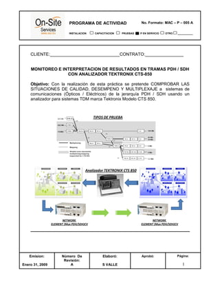
- 1. No. Formato: MAC – P – 005 APROGRAMA DE ACTIVIDAD INSTALACION CAPACITACION PRUEBAS P EN SERVICIO OTRO ___________ Emision: Enero 31, 2009 Número De Revisión: A Elaboró: S VALLE Aprobó: Página: 1 CLIENTE:_____________________________CONTRATO:________________ MONITOREO E INTERPRETACION DE RESULTADOS EN TRAMAS PDH / SDH CON ANALIZADOR TEKTRONIX CTS-850 Objetivo: Con la realización de esta práctica se pretende COMPROBAR LAS SITUACIONES DE CALIDAD, DESEMPENO Y MULTIPLEXAJE a sistemas de comunicaciones (Ópticos / Eléctricos) de la jerarquía PDH / SDH usando un analizador para sistemas TDM marca Tektronix Modelo CTS 850. TIPOS DE PRUEBA NETWORK ELEMENT (Mux PDH/SDH)CV Analizador TEKTRONIX CTS 850 NETWORK ELEMENT (Mux PDH/SDH)CV
- 2. No. Formato: MAC – P – 005 APROGRAMA DE ACTIVIDAD INSTALACION CAPACITACION PRUEBAS P EN SERVICIO OTRO ___________ Emision: Enero 31, 2009 Número De Revisión: A Elaboró: S VALLE Aprobó: Página: 2 MONITOREO E INTERPRETACION DE RESULTADOS EN TRAMAS PDH / SDH CON ANALIZADOR TEKTRONIX CTS-850 Equipamiento: Para la realización de las diversas mediciones en modo PDH, se generan señales a 2, 34 y 140 Mb/s en formato trama conforme a las recomendaciones ITU-T para estas velocidades. Así mismo, se reciben señales de las jerarquías indicadas y sobre una señal “Patrón” de prueba que se espera recibir, es que se calcula la calidad G- 821. Cabe resaltar que el analizador CTS-850 permite verificar el funcionamiento de toda la jerarquía de multiplexación de la señal recibida. (Utilizando la función AUTO SCAN.) En modo SDH se pueden generar señales de STM-1 a STM. A continuación un resumen de las MODOS DE PRUEBA del analizador TEKTRONIX CTS – 850:
- 3. No. Formato: MAC – P – 005 APROGRAMA DE ACTIVIDAD INSTALACION CAPACITACION PRUEBAS P EN SERVICIO OTRO ___________ Emision: Enero 31, 2009 Número De Revisión: A Elaboró: S VALLE Aprobó: Página: 3 A continuación se detalla la información que presenta el analizador CTS-850 a través algunas pantallas e indicaciones del panel frontal, de interés en la utilización de estos analizadores en medidas PDH. Panel frontal: En el panel frontal, se encuentran las terminales de acceso para salida y entrada de señal PDH: • Coaxial 75 ohmios velocidades 2, 34 y 140 Mb/s (No Balanceada) • 120 ohmios para velocidad de 2 Mb/s (Balanceada) En el panel frontal, se encuentran además las indicaciones luminosas que informan del estado del interfaz de entrada (STATUS de la señal recibida): • LOS: Pérdida de la señal (Loss of frame) • LOF: Pérdida de trama (Loss of signal) • SIGNAL PRESENT : Presencia de señal de prueba • PATTERN LOCK: Captura de señal de prueba Alarmas: 2, 34, 140 Mb/s • AIS: Señal de Indicación de alarma 2, 34, 140 Mb/s • RAI: Indicación de alarma remota
- 4. No. Formato: MAC – P – 005 APROGRAMA DE ACTIVIDAD INSTALACION CAPACITACION PRUEBAS P EN SERVICIO OTRO ___________ Emision: Enero 31, 2009 Número De Revisión: A Elaboró: S VALLE Aprobó: Página: 4 PANTALLA FRONTAL, INDICADORES Y CONTROLES DEL ANALIZADOR TEKTRONIX CTS 850 (1) (2)
- 5. No. Formato: MAC – P – 005 APROGRAMA DE ACTIVIDAD INSTALACION CAPACITACION PRUEBAS P EN SERVICIO OTRO ___________ Emision: Enero 31, 2009 Número De Revisión: A Elaboró: S VALLE Aprobó: Página: 5 PREPARACIÓN DEL EQUIPO PARA REALIZACIÓN DE MEDIDAS. Cuando se va a realizar una medida se debe pulsar la tecla TEST SETUPS y seleccionar opción TEST CONTROL, entonces aparecerá la pantalla: (3) (4) En la pantalla (3) se determina el tiempo de duración de la medida y la resolución de los histogramas. Para comenzar la prueba se pulsa la tecla START y una vez finalizada la medida se analizan los resultados pulsando RESULTS (4) y estudiando las pantallas (5 y 6) que se muestran a continuación: (5) (6)
- 6. No. Formato: MAC – P – 005 APROGRAMA DE ACTIVIDAD INSTALACION CAPACITACION PRUEBAS P EN SERVICIO OTRO ___________ Emision: Enero 31, 2009 Número De Revisión: A Elaboró: S VALLE Aprobó: Página: 6 En esta sección se da una idea de los principales MODOS DE PRUEBA usados en el CTS 850 tanto para sistemas SDH como PDH; Estos son: 1. Network Continuity Checking With the AUTOSCAN feature of the CTS 850, it is easy to make a quick continuity check. The continuity check verifies that a SDH network element (NE), or portion of the network, is correctly setup and provisioned and that the signal passes through intact. In this example, the CTS 850 transmits an STM-1 E signal in to an NE. Then the CTS 850 receives the output from the NE and verifies that the AU-4, including its payload patterns, is intact.
- 7. No. Formato: MAC – P – 005 APROGRAMA DE ACTIVIDAD INSTALACION CAPACITACION PRUEBAS P EN SERVICIO OTRO ___________ Emision: Enero 31, 2009 Número De Revisión: A Elaboró: S VALLE Aprobó: Página: 7 2. Transmission Signal Quality Testing The testing consists on Measuring Bit Error Rate. The bit error rate (BER) test is one of the best ways to measure the quality of an SDH transmission link. You can use the CTS 850 to make a BER test on a two-way link that is connected in a loop-back configuration. If this is a test you perform often, save it as a pass / fail test for easy recall. While the test is running, the CT S850 counts errors and errored seconds and then calculates the error ratio for each error type or errored seconds. After the time for testing in minutes, have elapsed, the test stops automatically and the measured results are held on the SDH RESULTS page until another test is started. When the test is complete, you can store the test results to disk or print out a hardcopy.
- 8. No. Formato: MAC – P – 005 APROGRAMA DE ACTIVIDAD INSTALACION CAPACITACION PRUEBAS P EN SERVICIO OTRO ___________ Emision: Enero 31, 2009 Número De Revisión: A Elaboró: S VALLE Aprobó: Página: 8 3. Fault Tolerance Testing Fault tolerance testing (sometimes called stimulus/response testing or stress testing) is used to ensure that a network responds correctly to various fault conditions. Though there are many additional fault conditions you can test with the CTS 850, this section covers three common examples: Response to errors and alarms Response to pointer movements Response to line frequency offset Example: Response to Errors and Alarms Note: This example uses two CTS 850 testers to simultaneously check the upstream and downstream responses to an error or alarm condition. BUT YOU CAN USE A SINGLE CTS 850 TO DO THE SAME THING BY ALTERNATELY.
- 9. No. Formato: MAC – P – 005 APROGRAMA DE ACTIVIDAD INSTALACION CAPACITACION PRUEBAS P EN SERVICIO OTRO ___________ Emision: Enero 31, 2009 Número De Revisión: A Elaboró: S VALLE Aprobó: Página: 9 4. Performance Monitoring When a new line is installed you may want to monitor performance for a day or so to be sure it Is operating correctly. Or, if problems are suspected on a line, you may want to run a long test to determine the cause of the problem. In either case, the CTS 850 makes it easy to monitor an electrical or optical line without the need for splitters. During a test, the CTS 850 simultaneously takes all performance measurements, analyzes the results according to the G.821standard, and displays the measurements and analysis in your choice of three formats: In a brief summary In detail by type (defect, anomaly, alarm, failure) In detail by layer (regenerator section, multiplexer section, path) In this example, the CTS 850 is placed directly in line with a live optical signal to monitor performance in a nun intrusive mode (Through Mode).
- 10. No. Formato: MAC – P – 005 APROGRAMA DE ACTIVIDAD INSTALACION CAPACITACION PRUEBAS P EN SERVICIO OTRO ___________ Emision: Enero 31, 2009 Número De Revisión: A Elaboró: S VALLE Aprobó: Página: 10 5. Jitter and Wander Testing With the CTS 850 jitter generation and analysis capability, it is easy to run the following automated ITU jitter conformance tests: • Jitter Tolerance • Jitter Transfer • Output Jitter (Jitter Generation) • Pointer Jitter Testing Jitter Tolerance The CTS 850 generates a signal that contains jitter at various frequencies and feeds it to the network element. Simultaneously, the CTS 850 receives the output from the network element and analyzes its performance. You can specify several parameters for the test: • Mask type for jitter analysis • Start frequency • End frequency • Number of frequency samples • Tolerance criteria The results are displayed in numerical and graphical form.
- 11. No. Formato: MAC – P – 005 APROGRAMA DE ACTIVIDAD INSTALACION CAPACITACION PRUEBAS P EN SERVICIO OTRO ___________ Emision: Enero 31, 2009 Número De Revisión: A Elaboró: S VALLE Aprobó: Página: 11 6. Timing Quality Testing Compressed digital video signals transmitted over a network can be impaired by low frequency jitter or frequency drift that may be acceptable in other applications. One source of this jitter is pointer movement used to synchronize SDH payloads across a network. You can use the CTS 850 to analyze jitter in a PDH signal due to pointer movement in the SDH signal. Two new measurements, Frequency Drift Rate and Pointer Hit Seconds, helps how this effect. The CTS 850 generates a SDH signal containing a sequence of pointer movements. The CTS 850 analyzes the timing of the dropped 34 Mb/s signal.
- 12. No. Formato: MAC – P – 005 APROGRAMA DE ACTIVIDAD INSTALACION CAPACITACION PRUEBAS P EN SERVICIO OTRO ___________ Emision: Enero 31, 2009 Número De Revisión: A Elaboró: S VALLE Aprobó: Página: 12 CONCLUSION: En este procedimiento se detalla brevemente la funcionalidad y los tipos de prueba que se pueden utilizar con el analizador TEKTRONIX CTS 850. Es responsabilidad del usuario determinar que pruebas se deben aplicar y cuales se pueden descartar dependiendo de la aplicación de las redes PDH/SDH tanto eléctricas como ópticas. Así como también, del nivel de multiplexaje requerido según sea el “performance” requerido por la aplicación. Los ejemplos aquí descritos son meramente ilustrativos y requiren un análisis detallado del problema manifestado por el clienta a la hora de implementarlos. Cualquier aplicación debe estudiarse en forma particular.