
Recomendados
Más contenido relacionado
La actualidad más candente
La actualidad más candente (20)
Similar a Manual técnico transmisor y antenas
Similar a Manual técnico transmisor y antenas (20)
Último
Último (20)
Manual técnico transmisor y antenas
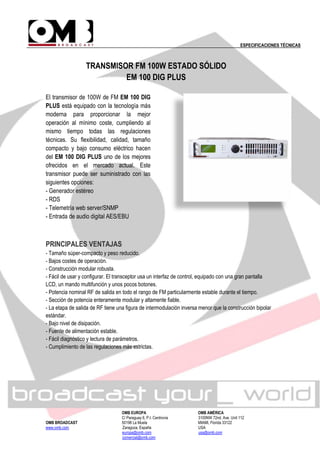
- 1. ESPECIFICACIONES TÉCNICAS OMB EUROPA OMB AMÉRICA C/ Paraguay 6, P.I. Centrovía 3100NW 72nd. Ave. Unit 112 OMB BROADCAST 50198 La Muela MIAMI, Florida 33122 www.omb.com Zaragoza, España USA europa@omb.com usa@omb.com comercial@omb.com TRANSMISOR FM 100W ESTADO SÓLIDO EM 100 DIG PLUS El transmisor de 100W de FM EM 100 DIG PLUS está equipado con la tecnología más moderna para proporcionar la mejor operación al mínimo coste, cumpliendo al mismo tiempo todas las regulaciones técnicas. Su flexibilidad, calidad, tamaño compacto y bajo consumo eléctrico hacen del EM 100 DIG PLUS uno de los mejores ofrecidos en el mercado actual. Este transmisor puede ser suministrado con las siguientes opciones: - Generador estéreo - RDS - Telemetría web server/SNMP - Entrada de audio digital AES/EBU PRINCIPALES VENTAJAS - Tamaño súper-compacto y peso reducido. - Bajos costes de operación. - Construcción modular robusta. - Fácil de usar y configurar. El transceptor usa un interfaz de control, equipado con una gran pantalla LCD, un mando multifunción y unos pocos botones. - Potencia nominal RF de salida en todo el rango de FM particularmente estable durante el tiempo. - Sección de potencia enteramente modular y altamente fiable. - La etapa de salida de RF tiene una figura de intermodulación inversa menor que la construcción bipolar estándar. - Bajo nivel de disipación. - Fuente de alimentación estable. - Fácil diagnóstico y lectura de parámetros. - Cumplimiento de las regulaciones más estrictas.
- 2. ESPECIFICACIONES TÉCNICAS OMB EUROPA OMB AMÉRICA C/ Paraguay 6, P.I. Centrovía 3100NW 72nd. Ave. Unit 112 OMB BROADCAST 50198 La Muela MIAMI, Florida 33122 www.omb.com Zaragoza, España USA europa@omb.com usa@omb.com comercial@omb.com CARACTERÍSTICAS GENERALES RANGO DE FRECUENCIA 87.5-108MHz MODULACIÓN FM 75KHZ (ajustable) desviación de pico. Mono 180kF3E y Estéreo 256kF3E NIVEL DE ENTRADA AUDIO/MPX -3.5 a +12.5dBm @ 75KHz desviación CONECTORES DE ENTRADA DE AUDIO XLR(H) CONECTOR ENTRADA DIGITAL AES/EBU (OPCIONAL) XLR(H), 110Ω balanceado SEPARACIÓN ENTRE CANALES (GENERADOR ESTÉREO OPCIONAL) 60dB NIVEL DE ENTRADA DE CANAL AUXILIAR (RDS/SCA) 7.5KHz desviación: -12.5 a 3.5dBm 2KHz desviación: -24 a -8dBm IMPEDANCIA DE ENTRADA CANAL AUX. 10kOhm DISTORSIÓN DE MODULACIÓN 7.5KHz desviación: <0.05%, 0.02% típico 2KHz desviación: <0.2%, 0.05% típico RELACIÓN S/N MONO 30 a 20000Hz: >76dB, 86dB típico CCIR: >75dB, 81dB típico RELACIÓN S/N ESTÉREO 30 a 20000Hz: >72dB, 77dB típico CCIR: >68dB, 72dB típico ANCHO DE BANDA CANALES DE AUDIO 30 a 15000Hz ±0.1dB CONSTANTE DE TIEMPO DE PRE-ÉNFASIS Seleccionable, 25/50/75 microsegundos POTENCIA DE SALIDA RF NOMINAL RF 100W PASOS DE SINTONIZACIÓN DEL TRANSMISOR 10/100KHz ESTABILIDAD ALC DE POTENCIA DE SALIDA ±3% EMISIONES ESPURIAS Y ARMÓNICOS <80dBc IMPEDANCIA DE SALIDA RF 50Ω CONECTOR DE SALIDA DE RF Tipo N CONECTOR MUESTREO RF Tipo BNC ALIMENTACIÓN 110-230Vac ±15% 50/60Hz CONSUMO 141VA (100W) RANGO DE TEMPERATURA DE OPERACIÓN 0 a 35°C recomendado, -10 a +55° máx. HUMEDAD RELATIVA Hasta 95% sin condensación * Las imágenes y/o características técnicas pueden sufrir modificaciones sin previo aviso.
- 3. Telecomunicazioni Ferrara 26 Model AJ1E – AJ1EBI – AJ1E/INOX – AJ1E/IT TELECOMUNICAZIONIFERRARA RVR GROUP RVRGROUP • High Power Version (H.P.) • FM Band 87.5÷108 MHz • Suitable for VHF, Band I and OIRT Band • Gamma Match Tuned • Omni directional pattern • Vertical polarization • Light - Low Cost - Demountable “These specifications are subject to change without notice” L H Input connector W RADIATION PATTERN (MID BAND) ELECTRICAL DATA Frequency range 87.5÷108 MHz Impedance 50 Ohm Connectors N or 7/16” female or 7/8” EIA Max Power 650W (N) – 1300W (7/16” – H.P. Version) VSWR ≤ 1.1:1 in the operating channel Polarization Vertical Gain 1 dB (referred to half-wave dipole) Pattern Omni directional ± 1.5 dB in free space Omni directional ± 3 dB with 100mm dia. pole Lightning protection No DC grounded E-Plane H-Plane MECHANICAL DATA Dimensions According to the working frequency 1380 (H) x 760 (L) x 100 (W) mm at 98 MHz Weight According to the working frequency (aluminium or stainless steel) Wind surface 0.05 m2 (at 98 MHz) Wind load 6.7 kg (wind speed at 160 km/h) Max wind velocity 200 km/h (AJ1E/IT model) AJ1E: Aluminium elements and boom AJ1EBI: Aluminium elements and inox boom AJ1E/INOX: Stainless steel elements and boom Materials AJ1E/IT: Stainless steel elements and boom Tig Welded Version Teflon insulator Radome: fiberglass (option) Icing protection Feed point radome (optional) Radome Optional Mounting With special pipe clamps 50÷110 mm dia. 180 0 270 90 -1 330 300 240 210 150 120 60 30 -2 -3 -4 -6 -9 -15 180 0 270 90 -1 330 300 240 210 150 120 60 30 -2 -3 -4 -6 -9 -15
- 4. 27 RVR GROUP Radiations systems with AJ1E antenna Omni-directional pattern Gain is provided for vertical polarization. When antenna is pole mounted on the top a tower the horizontally polarized radiation pattern is omni - directional. If the antenna is side mounted, the supporting structure will have a slight effect on the radiation pattern and VSWR. Vertical tower space, wind load and weight numbers given are typical. Actual values vary with the specific installation. Contact us for more details of your installation. Gain will be reduced if null fill, beam tilt or special wavelength spacing is provided. Antenna radiation aperture is the distance from the centre of the top bay to the centre of the bottom bay. Five ft(1.6mt) of pipe required above the top bay and below the bottom bay for to protect from pattern interference by other antennas. Antenna wind load is calculated for 100 Mph (160Km/h) per EIA-222-C standard. 1 Referred to a half wave dipole. Attenuation of connecting cables not taken into account. 2 Without mounting hardware. 3 The systems comprised: antennas, cables and splitter – for more details to see catalog – different version on request. TECHNICAL DATA RVRGROUP TELECOMUNICAZIONIFERRARA Model AJ1E – AJ1EBI – AJ1E/INOX – AJ1E/IT Number Dipole Gain1 Weight2 Antenna Wind load COLLINEARS SYSTEMS 3 of per height L (v=160 km/h) bays bay dB times kg m kg 800 W 1 KW 2 KW 3 KW 5 KW 1 1 1.0 1.2 - 1.4 14 AJ1E AJ1E(HP) - - - 2 1 4.0 2.5 - 4.0 28 - AJ1EX21 - - - 4 1 7.0 5.0 - 9.2 57 AJ1EX41 - AJ1EX42 AJ1EX43 - 6 1 8.8 8.5 - 14.4 85 AJ1EX61 - AJ1EX62 AJ1EX63 - 8 1 10.0 10.0 - 19.6 113 AJ1EX81 - AJ1EX82 - AJ1EX85 ELECTRICAL DATA Frequency range 87.5÷108 MHz Impedance 50 Ohm Connector EIA flange according to system power rating VSWR ≤ 1.1:1 Max Polarization Vertical Gain According to requirement Horizontal pattern Any type according to requirements Vertical pattern Null fill, beam tilt and special requirements to order Other facilities The antenna system can be supplied in split feed with two equal half antennas. Each half can accept full power MECHANICAL DATA Height of array Subject to number of bays ( refer to table ) Total net weight According to the working frequency Wind load Refer to table (at 98 MHz) Pressurizzable No Radome Optional Mounting hardware Hot dip galvanized steel clamps Shipping As required Telecomunicazioni Ferrara L 2600 mm (at 98 MHz) “These specifications are subject to change without notice”